Research Article | | Peer-Reviewed

Calibration of Radioisotope Level Gauge Detector

Received: 6 February 2026     Accepted: 19 March 2026     Published: 27 August 2026
Views:       Downloads:
Abstract

In accordance with regulatory standards, to meet the requirements of legislation in the field of industrial safety and ensure the quality of fiberglass products, as well as to confirm the correct operation of the measuring instrument, accurate calibration of the radioisotope measuring instrument is necessary.The aim of this work is to develop a method for testing the tightness of the Cesium-137 ionizing radiation source included in the radioisotope level gauge, to develop a method for accurately calibrating the radioisotope level gauge in laboratory conditions and to install the radioisotope level gauge in the preliminary channel of technological line of glass fiber production for continuous measurement of the glass mass level in online mode. The leak tightness of the Cs-137 radioactive ionizing radiation source was tested using three different methods. To calibrate the radioisotope level gauge in a laboratory conditions, a stainless steel calibration stend was used. The stand consisted of a square container with an internal lining of firebrick, and a mixture of bromoform and ethyl alcohol with a density of ρ=1799 g/dm3 was used as a simulant liquid. A gamma source block with a Сs-137 source was installed on one side of the pre-channel, and a detector was installed on the diametrically opposite side. One external firebrick in front of the detector was removed from the pre-channel, and the resulting void was filled with fiberglass to protect the detector from heating due to the high temperature of the fiberglass. The radioisotope level gauge detector (M7213 scintillation probe, Tesakon Messele-lectronics, GmbH Dresden), which has a housing with a water cooling system and a scintillation crystal length of 35 mm (Φ=38 mm, H=38 mm), was calibrated to an acceptable glass mass level of 192.5 mm (±1 mm) from the bottom of the preliminary channel at a maximum γ-radiation flux from a Cs-137 ionizing radiation source with an intensity of 1660 pulses/sec.

Published in World Journal of Applied Physics (Volume 11, Issue 3)
DOI 10.11648/j.wjap.20261103.11
Page(s) 30-39
Creative Commons

This is an Open Access article, distributed under the terms of the Creative Commons Attribution 4.0 International License (http://creativecommons.org/licenses/by/4.0/), which permits unrestricted use, distribution and reproduction in any medium or format, provided the original work is properly cited.

Copyright

Copyright © The Author(s), 2026. Published by Science Publishing Group

Keywords

Preliminary Channel, Liquid Glass, Radionuclide Cs-137, Detection Block, Calibration Stand, Bromoform, Ethyl Alcohol, Calibration

1. Introduction
The company “Falk Porshe Fiberglass” JV LLC (Tashkent, Republic of Uzbekistan) is a plant that produces white E-glass, roving text: 1200 2400 4800 9600 for the production of drones, automobiles, railway and aviation equipment, highways and bridges, composite pipes, and hundreds of other important objects.
Glass fiber (GF) is one of the main reinforcing elements, accounting for almost 90% of the reinforcing materials used in global polymer composite consumption and more than 85% of pultruded products currently produced worldwide are Class E glass fiber composites . Glass fiber roving is a versatile composite reinforcing material available in a variety of linear densities measured in tex, a unit representing grams per 1,000 meters. Common specifications include 4800 tex, 2400 tex, and 1200 tex, each suited to different manufacturing processes and performance requirements. Straight roving is widely used in the following end-use processes: filament winding to create hollow tubular structures (pipes, storage tanks, and pressure vessels); knitting and weaving for composite profiles; consumer product applications (sports and recreational equipment, telecommunications, and infrastructure); and the semi-finished product (fabric) can be used in a variety of applications (wind energy, marine, transportation, sports and recreation, and infrastructure).
Finished 2400 tex fiberglass product applications include: 1) It`s is often used in aircraft components, providing exceptional strength and rigidity with minimal weight, which is important for improving aircraft efficiency and reducing fuel consumption; 2) 2400tex fiberglass is used in the production of lightweight body parts, chassis components, and interior trim elements, which helps reduce overall vehicle weight, improve fuel efficiency, and improve handling; 3) 2400 tex fiberglass roving is widely used in the wind energy industry for the production of wind turbine blades because its high strength and durability enable the blades to withstand extreme wind conditions and provide a long service life; 4) Glass fiber reinforced plastics (GFRP) are widely used in the construction of small vessels (fishing boats and yachts) , because its resistance to corrosion and moisture makes it an ideal material for ensuring strength and long-term use; 5) GFRP are widely used as well as as a reinforcing material in concrete and other composite structures, providing increased strength and durability. They can also be used to produce lightweight roofing materials and thermal insulation panels; 6) 2400 tex glass fiber roving is an excellent material for electrical and electronic devices due to its excellent electrical conductivity and insulating properties and is used in the production of cables, wire harnesses and other electrical components.
In recent years, radioisotope devices in metallurgy, mineral extraction, chemical industry, gas production, fiber optic production and other industries was been successfully used. The high sensitivity of the equipment allows for the measurement of controlled parameters without taking samples – using non-destructive testing methods. The radioisotope density meter is designed for non-contact measurement of the density of pulps and liquid media in pipelines . The radioisotope level gauges is designed for non-contact measurement of level and signaling of technological products (petroleum coke and foam in coke chambers, liquid sulfur and chemically harmful acids in bulk ectakades, gas condensate and powdered polypropylene intermediate product in closed containers . The radioisotope devices provides rapid continuous measurement of density or level of technological products and conversion of the obtained density or level value to the output current signal, as well as alarm control when the main parameter goes beyond the specified range and registers the results obtained. The main advantage of the radioisotope method for measuring density or level is non-contact, which allows it to be used in determining the density or level of aggressive and viscous media, as well as liquids under high pressure or temperature, where the use of other types of instruments is almost impossible. According to IAEA requirements, the main purposes of calibration of a radioisotope instrument are: 1) To ensure that the instrument is operating correctly; 2) To determine, under a controlled set of standard conditions, the instrument readings as a function of the measure value (the quantity intended to be measured); 3) Calibrate the instrument in such a way as to optimize the overall measurement accuracy of the instrument.
In the in special furnaces, a mixture of kaolin, limestone, sodium sulfate and colemanite is dissolved at a temperature of 1550°C. This hot glass mass then is passed through a prelimi-nary channel, where level of liquid glass is measured by radioisotope level gauge M7213 scintillation probe (Tesakon Messele-lectronics, GmbH Dresden) in on-line regime. Preliminary calibration of radioisotope level gauge in laboratory conditions and it`s adjustment on the production line is an important and urgent task to ensure uniform flow of high-temperature (T=1088°C) liquid glass through the preliminary channel and to obtain high-quality products..
The aim of the study is to develop a method for calibrating the M7213 radioisotope level gauge in laboratory conditions by constructing a stand and calibration fluid, performing precise calibration of the measuring instrument to the required level, installing the radioisotope level meter in a preliminary channel and ensuring continuous operation of the measuring instrument in online mode.
2. Results and Discussion
2.1. Technological Properties of Fiberglass
The term E-glass is used to describe alumino-borosilicate glass with an alkali content of less than 2%. E-glass is produced into extremely fine, long filaments (fibers) (Table 1).
Typical properties of some glass fibers are shown in Table 1.
Table 1. Typical properties of some glass fibers.

Type of fiberglass

Density (g/сm3)

Tensile strength (GPa)

Young's modulus (GPa)

E-glass

2.54

1.7–3.5

69–72

S-glass

2.48

2,0–4,5

85

С-glass

2.48

1.7–2.8

70

2.2. Stages of Fiberglass Production
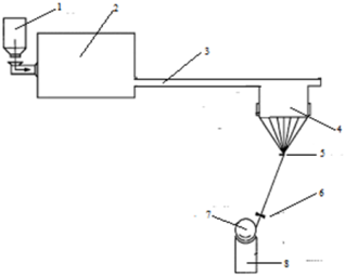
A schematic picture of the traditional glass fiber manufacturing procedure is shown in Figure 1.
Figure 1. Schematic diagram of the traditional fiberglass manufacturing process.
1- hopper; 2- furnace; 3-pre-channal; 4 – platinum bushing; 5 - filament collecting and size applicator; 6 - strand transverse motion; 7 – collet; 8 – winding head unit.
The raw material is heated in a hopper (1) and in special furnaces (2), a mixture of kaolin, limestone, sodium sulfate and colemanite is dissolved at a temperature of 1550°C. The molten glass passes through a pre-channel (3) and is then fed into electrically heated platinum or platinum-rhodium bushings (4) with multiple holes. Typically, a screw-type sleeve has 200 holes in its base. A constant level of molten glass is maintained in the reservoir. The molten glass flows by gravity through these holes, forming a web of continuous threads. which are collected together and passed around a rapidly rotating collet, after which they are pulled out at a speed of 1–2 km/min. This hot glass mass then is passed through a preliminary channel, where level of liquid glass is measured by radioisotope level gauge M7213 scintillation probe (Tesakon Messelelectronics, GmbH Dresden) in on-line regime. Preliminary calibration of radioisotope level gauge in laboratory conditions and it`s adjustment on the production line is an important and urgent task to ensure uniform flow of high-temperature (T=1088°C) liquid glass through the preliminary channel and to obtain high-quality products.
The production of fiberglass involves the following stages:
Stage 1: Preparing batches process. Precisely measured quantities of silica and additives are mixed. The Table 2 shows the percentages of individual additives in different types of glass. The composition of fiberglass varies significantly depending on its intended use, from insulating wool to high-strength aerospace components. Additives, typically in the form of oxides, are added to modify viscosity, chemical resistance, and dielectric properties.
Table 2. Percentages of individual additives in different types of fiberglass .

Glass E (with boron)

Glass E (boron-free)

SiO 2

52-56%

Al₂O₃

12-16%

B2О3

5-10%

CaO

16-25%

MgO

0-5%

Na2O

0-2% (used to reduce the melting point of glass mass).

К2О

0-2% (used to reduce the melting point of glass mass)

ТiО2

0,2-1,5%

Fe₂O₃

0 -0,4%

F2

0-0,7%

Softening threshold

840°C

Stage 2: Melting process. A pre-charged batch of glass is fed into a high-temperature furnace fueled by natural gas for melting at ~ 1400°C. The furnace is typically divided into three sections. The first section is where the batch is melted. The molten mixture enters the second section, the refiner, where the temperature is reduced to ~ 1370°C. The final, third section is the hearth furnace, where the molten glass passes through a pre-channel, which is equipped with a radioisotope level gauge to maintain a precise level of the flowing glass. If the glass melt level is below a certain specified value, the glass may break when extruding into fiber. If the level of the molten glass is higher than a certain specified value, then when the molten glass is extruded into fiber, the fiber diameter may increase. The flowing glass is then fed into platinum and rhodium bushings, which are used to extrude the molten glass into fibers. This completes the melting stage.
Stage 3: Fiberizatio process. Glass fibre formation involves a combination of extrusion and quenching. During extrusion, molten glass exits the furnace through a core made of a wear-resistant platinum-rhodium alloy with very fine holes. A single core can have between 200 and 8,000 such holes. The core plates are electronically heated, and their temperature is precisely controlled to maintain a constant glass viscosity. Water jets cool the filaments exiting the core to approximately 1200°C. The molten streams are then captured by a high-speed winder. The molten streams are then captured by a high-speed winder, which rotates much faster than the flow of molten glass, and as they exit the bushings, tension is created, drawing them into thin threads with a diameter of 4 to 34 microns.
Stage 4: Coating process. At this stage, mechanical winders pull the fibers at a speed of 61 m/s through an applicator, which coats the fibers with a suitable chemical coating, called a preservative, to facilitate further processing and improve the quality of the final product. The chemical composition of the resin is crucial to the performance of fiberglass. For example, the chemical composition of the resin used in the production of wind turbine blades can increase the blade's service life by an order of magnitude.
Preservatives typically contain between 0.5 and 2.0% by weight and may include lubricants, binders, and/or coupling agents.
Stage 5: Drying and Packaging process.. Finally, the drawn and processed yarns are collected into a bundle. A bundle consists of a strand containing between 51 and 1,624 yarns. The strand is wound onto a drum into a forming package, which resembles a spool of yarn. The forming packages, still damp from water cooling and processing, are then dried in an oven. They are then ready for palletizing and shipping or further processing into chopped fiber, roving, or yarn. Rovings are made from one or more yarns, which can be twisted to improve the yarn's integrity in subsequent processes, such as weaving. For example, a collected roving consisting of 10-15 yarns is wound together into a multi-filament roving package.
Continuous glass fibers (the first type of fiber used in modern composites) are made by drawing molten glass (at about 1300°C) through dies with a diameter of 0.8–3.0 mm and then stretching it at high speed to a diameter of 3–19 µm .
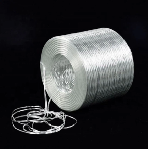
Figure 2 shows the finished glass fiber roving product.
Figure 2. Fiber roving product.
2.3. The Operating Principle of a Radioisotope Level Gauge
The gamma source block of the level gauge uses a Cs-137 source with the radionuclide 137Cs (T1/2=30.17 years), which undergoes beta decay, as a result of which the isomer 137m1Ba (T1/2=2.552 min) is initially formed, which with a probability of 94.4% is converted into the stable isotope 137Ba:
137Сs137m1Ba+e+<i></i>e;(1)
37m1Ba137Ba+<i></i>(2)
In 94.4% of cases, the 137mBa radionuclide by nuclear reaction (2) transforms into the ground state of the stable isotope 137Ba with the emission of - rays with an energy of 661.7 keV (by nuclear reaction 3), which are recorded by the detection block.
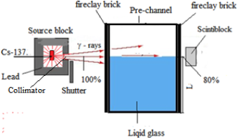
The operation of radioisotope devices (radioisotope densitometers, radioisotope level gauges and gamma relays) is based on the reaction (1 and 2), when gamma-radiation ( electromagnetic radiation) passes through the control object, is weakened as a result of absorption by a technological product and registered by a scintillation detector, amplified and converted into electric current, processed in the information processing block and displayed on the device display with information about the density or level of the measured product. Figure 2 shows a diagram of the passage of gamma quanta through the measured medium (glass mixture) and their registration by the detector of a radioisotope level gauge.
Figure 3. Schematic diagram of the passage of gamma quanta through the measured medium (glass mixture) and their registration by the detector of a radioisotope level gauge.
As shown in Figure 3, the level gauge detection blockmeasures the glass melt level (L) with an accuracy of ±1 mm.
If the glass mass level is below or above this calibrated level, the intensity of the gamma quanta changes, that is, when the glass mass level is above this level, the intensity of the gamma quanta decreases due to absorption by the dense glass mass, and when the glass mass level is below this level, the intensity of the gamma quanta increases because the detector captures gamma quanta passing through a less dense air medium.
2.4. Checking the Tightness of the Ionizing Radiation Source
According to the «Code of Conduct on the Safety and Security of Radioactive Sources» of IAEA and to regulations , after the expiration of the specified service life, each closed ionization radiation source must undergo a leak test and a lifetime extension or must be buried in a specialized facility for the disposal of radioactive sources. This is due to the fact that during operation under extreme conditions (high humidity, temperature, pressure) the tightness of a closed source of ionizing radiation may be compromised. The radioactive source of ionizing radiation cesium-137 has a designated service life of 15 years, after which it is necessary to check its tightness and extend its service life.
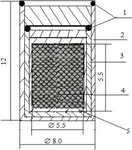
Figure 4 shows a diagram of a closed radioactive source of ionizing radiation Cs-137.
The tightness of the radioactive source Cs-137 was checked using 3 different methods and the loading of the sealed source of Cs-137 into the gamma source block of the radioisotope level gauge was carried out in a special protective box using a remote method, which eliminates overexposure of personnel.
The Cs-137 ionizing radiation source can be tested by 3 leak testing methods.
Figure 4. Closed radioactive source of ionizing radiation Cs-137: 1-hermetic welding; 2 - outer capsule; 3 - internal capsule; 4 - radionuclide Cs-137; 5 - glass.
Method 1 was a immersion radiometric method for monitoring the tightness of a source of any type with a stainless steel capsule is carried out by immersing the source in an immersion liquid, for which the manufacturer recommends using a 7-10% solution of nitric acid heated at a temperature of 60-90°C for 1 hour . However, a use of HNO3 can corrode the end-of-life radioactive source. The source is immersed in a liquid that does not act on the capsule material, but effectively leaches radioactive substances. The immersion liquid (aqueous 10% solution of Trilon B - 2-aqueous solution of disodium salt of ethylenediaminetetraacetic acid) or 10-15% aqueous solution of H3PO4 is heated to boiling for 10 minutes and cooled to room temperature. The cycle is repeated 2-3 times . The activity of radionuclides that have passed into the liquid should not exceed 185 Bq (5 nCi). The results showed that the radiometric immersion method, where a 10–15% aqueous solution of H3PO4 was used as an immersion liquid, is the most appropriate for testing the leak tightness of sources with expired designated service life because when using this method an aqueous solution of H3PO4 exhibits a passivating property and forms a protective film on the source surface that protects the source capsule from corrosion, Phosphate coatings on steel form through a chemical reaction with dilute phosphoric acid and metal ions, creating a tightly bonded, microcrystalline protective layer .
The activity of the immersion extract is measured according to the method of measuring the specific activity of gamma-emitting radionuclides in countable samples using a CANBERRA semiconductor gamma spectrometer with a germanium detector and Genie-2000 software for quantitative analysis of gamma spectra of radionuclides or the gamma-beta spectrometer "RADEK" MKGB-01 (Russia). The activity (A) of the measured acid extract is calculated by the formula:
A=AcN1 ·N2(3)
where: Ac is the activity of the control solution with the radionuclide Cs-137 with known activity; N1 is the acid extract counting rate; N2 is the counting rate of the control solution.
If the activity of the immersion liquid does not exceed 185 Bq (~5 nCi), then the source is considered sealed .
Method 2 was a vacuum-liquid (bubble) method. The source of ionizing radiation is immersed in a liquid (ethylene glycol, alcohol, silicone oil or water) in a vacuum chamber, where a vacuum of 15-25 kPa is created. The absence of bubbles within 1 minute indicates the tightness of the source.
Method 3 was a smear radiometric method, which was based on the removal of possible contamination with radionuclides from the surface of the source with a wet or dry swab. The swab can be moistened with water, a dilute solution of nitric acid, or another solution that does not act on the capsule material, but actively removes radioactive contamination. When checking the tightness of sources by the smear method, the activity of radionuclides on a swab should be no more than 185 Bq (~5 nCi).
The leak test of the Cs-137 ionizing radiation source (serial number #413-04-01) with activity 3.33 1010 Bk (0.9 Ci) showed that Cs-137 source is leak-proof and can be used in the radiation source block of the radioisotope level gauge. A sealed cesium-137 source was loaded into the radioisotope level gauge source block and was installed in the radioisotope level mounting axis in the preliminary channel.
The level gauge detector consists of a scintillator, a photomultiplier, and a signal processing block. A scintillation detector consists of a scintillator crystal (NaI (Tl), CsI, SrI, BGO, etc.) coupled to an electronic light detector, which is usually a photomultiplier tube (PMT). The incoming gamma radiation flux causes flashes of light in the scintillator. The latter converts each photon of light emitted by the scintillator into an electrical pulse that provides meaningful information about the energy released by the incident radiation.
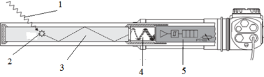
Figure 5 shows a general scheme of the operating principle of the radioisotope level gauge (detector).
In the radioisotope level gauge (detector) gamma radiation is converted into a flow of electrons and then amplified. The photomultiplier converts these flashes into electrical pulses and amplifies them. The pulse frequency (the number of pulses per second) is a measure of the intensity of the gamma radiation. In the detection block, the gamma radiation flux of source Cs-137 is converted into a sequence of statistically distributed pulses with an average repetition rate depending on the density of the measured pulp, and the density of the emulsion pulp is displayed on the displays of the information processing and analysis block and on the computer monitor in real time.
Figure 5. General scheme of the operating principle of the radioisotope level gauge (detector): 1 - gamma ionization radiation source Cs-137 (high energy photons); 2 - primary electron (low energy photon); 3 – scintillator; 4 - secondary electrons and their strengthening; 5 - information processing block that calculates the measured density value based on the pulse frequency.
The number of primary electrons is proportional to the energy of the incident high-energy gamma radiation (E=661.7 keV) from the radioactive source Cs-137. The primary electrons move toward the first dynode and are accelerated by the electric field. Each of them arrives a kinetic energy of ≈100 eV, transferred by the potential difference. When hitting the first dynode, more low-energy electrons are emitted, which in turn are accelerated toward the second dynode. The geometry of the dynode chain is such that the cascade occurs with an exponentially increasing number of electrons produced at each stage. If at each stage an average of 5 new electrons are produced for each incoming electron, and if there are 12 dynode stages, then at the last stage one would expect for each primary electron about 512 ≈ 108 electrons. Сurrent gain coefficient ki = σn. For example, if σ = 10 and n = 8, then ki = 108. This large number of electrons reaching the anode results in a sharp current pulse .
The sensitivity of the radioisotope level gauge M7213 scintillation probe is 20-50 times higher than the sensitivity of the Geiger-Muller counter.
The technical data of the scintillation probe are given in Table 3.
Table 3. Technical characteristics of the radioisotope level gauge M7213 scintillation probe.

Technical data

Characteristics of the indication

Detector: Scintillator

Diameter - 38 mm, Length – 38 mm

Photomultiplier

9134 V

Lower threshold for -quanta

45 keV in stabilization mode Cs-137

Detector sensitivity, pulses/sec

1.3·103 160

Gamma radiation background

approximately 120 pulses/sec at the entrance to the detector without peak stabilization, i.e. at a constant high voltage

Electric current used

30 mA

Maximum cable length

1000 m

Probe body material

High quality stainless steel, X6CrNiTi1810

Explosion safety

EExd ia IIC T6

Operating temperature range

(-20…+50)°C with cooling to 100°C

Cooling agent

filtered water

Coolant Temperature

25°C

Dimensions of the Cs-137 source

height 12 mm, diameter – 8mm

Activity Cs-137 source

3.33·1010 Bq (0.9 Ci)

Minimum dose for -peak stabilization

1 mGy/h

2.5. Calibration of Radioisotope Level Gauge
Table 4. The ratio of the components of liquid simulators of a controlled environment.

Density value, g/dm3

Composition of simulators, in% by volume

bromoform

ethyl alcohol

1800

48.0

52.0

2000

57.5

42.5

2200

67.0

33.0

A simulation bench solution was prepared, the density of which corresponded to the density of liquid glass. Petroleum ether, gasoline, benzene (=650-860 g/dm3), water-alcohol solutions (=870-950 g/dm3), sulfur-wine solutions (=960-1010 g/dm3), sulfur-water solutions (=960-1830 g/dm3), Thule solutions (=1840-2000 g/dm3) can be used as bench simulating solutions, however, they have aggressive properties and are highly toxic to human health .
Liquid simulators based on a mixture of tribromomethane (bromoform) and ethyl alcohol were used to calibrate a radioisotope densitometer . To prepare liquid simulants with different densities, tribromomethane CHBr3 stabilized with resorcinol and ethyl alcohol (C2H5OH) were mixed in 5.0 L glass containers in the following ratios (Table 4).
The radioisotope level gauge – M7213 scintillation probe was calibrated by use special calibration stand with liquid simulators based on a mixture of bromoform and ethyl alcohol with a density of 1799 g/dm3. In the laboratory conditions, a full-size metal preliminary channel stand with walls made of fireclay bricks was manufactured, into which a detector was installed on one side, and a source block with a Cs-137 source was installed on the diametrically opposite side. The calibration rig was made of stainless steel according to the dimensions of the preliminary channel (Figure 6), in the form of a square container with an internal lining of firebricks.
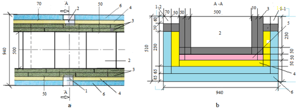
Figure 6 shows the diagram of the front preliminary channel for glass mass and the installation axis of the device.
Figure 6. Scheme of the preliminary channel for glass mass.
Top view (a) and cross-sectional view (b): 1-1 – mounting axis of radioisotope level gauge detector; 1-2 – mounting axis of radioisotope level gauge source block; 2 – glass mass channel; 3 – fireclay brick; 4 – thermal insulation; 5 – heater; 6 – frame.
In the line for the production of optical fiber, liquid glass at 1088°C flows through a preliminary channel that has the following size: internal dimensions - (230×510×230) mm; external dimensions- (500×940×500) mm; dimensions of wall – (170×280×170) mm. The preliminary channel for glass mass is made of fireclay bricks, which are used for laying furnace furnaces, chimneys and other structures and have direct contact with fire and withstand temperatures up to 1800°C. The fireclay brick SHA-9 (straight) type has dimensions – (300×150×65) mm and density of 1.9 g/cm3, so it absorbs of gamma radiation of radionuclide 137Cs very well. Taking this into account, before installing the scintillation sensor, one fireclay brick was removed symmetrically to the left and right (on both sides) of the measuring device installation axis from the preliminary channel wall body, and the resulting voids (100 mm) were filled on both sides with kaolin wool for thermal insulation of the level sensor.
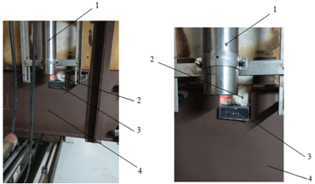
Figure 7 shows detector of radioisotope level gauge M7213 scintillation probe installed in the liquid glass channel of optical fiber production.
Figure 7. Detector of radioisotope level gauge M7213 scintillation probe installed in the liquid glass channel of optical fiber production. 1- scintillation probe detector; 2- kaolin wool; 3 - fireclay brick; 4 - metal body of the preliminary channel for liquid glass mass.
As can be seen in Figure 7, kaolin wool (2) is located between the detector (1) and the refractory brick (3). When installing the radioisotope level gauge in the preliminary channel, one of the two refractory bricks (on the outer side of the channel wall) was removed, and the resulting space was filled with glass wool.
Thus, the detector of a radioisotope level gauge, having a casing with a cooling water system, with a scintillation crystal length of 35 mm (=38 mm, H=38 mm) was calibrated to the permissible level of the -radiation flux of the ionizing radiation source Cs-137 at a level of 192.5 mm (1 mm) from the bottom of the pre-channel, where the intensity of -quanta is 1660 pulses/sec. If the glass mass level exceeds the calibration level (for example, 210 mm), a decrease in the intensity of gamma quanta to ≤120 pulses/sec is observed, and if the glass mass level decreases from the calibration level (for example, 185 mm), then an increase in the intensity of gamma quanta occurs (>1660 pulses/sec).
3. Conclusion
The tightness of the Cs-137 source with activity of 3.331010 Bq (0.9 Ci) was checked and into the gamma source block was loaded. To calibrate preliminary level of gauge detector M7213 scintillation probe metal simulator and liquid simulators with density =1799 g/dm3 were used. A calibrated radioisotope level gauge was installed in a liquid glass pre-channel of technological production line for continuous measurement of the liquid glass level in online mode.
Abbreviations

Сi

Curie, 1 Ci = 3,7·1010 Bk

Bk

Beckerl, (1 Bk=1 ipm/sec)

Gr

Gray

IAEA

International Atomic Energy Agency

T1/2

half-life

SI

International System of Units

kPa

Kilopascal (unit of pressure in the SI, equal to 1000 pascals)

V

Volt

A

Ampere

E-glass

Electrical Insulating Glass (Aluminoborosilicate Glass Fiber)

S-glass

Fiberglass (high-strength, high-stiffness)

C-glass

Fiberglass (strong, lightweight, durable and corrosion resistant).

CHBr3

Tribromomethane

C2H5OH

Ethyl Alcohol

SHA-9

Fireclay Brick Straight Type

Acknowledgments
The work was carried out using basic funding allocated to the Institute of Nuclear Physics of the Academy of Sciences of the Republic of Uzbekistan.
Author Contributions
Ulugbek Ashrapov: Conceptualization, Methodology, Supervision, Writing – original draft, Writing – review & editing
Shavkat Malikov: Data curation, Funding acquisition, Project administration
Muzaffar Erdanov: Investigation, Resources
Otabek Amanov: Investigation, Resources
Mukhtorjon Aminjanov: Methodology, Software, Supervision, Validation, Visualization
Rustem Ibraimov: Resources, Visualization
Conflicts of Interest
The authors of this article declare that they have no conflicts of interest.
References
[1] Jurko M., Soukova L., Prokes J., Chekh V. The Effect of Glass Fiber Storage Time on the Mechanical Properties of a Polymer Composite. Polymers 2022, 14 (21), 4633;
[2] Bobovich, B. Use of Glass Roving for the Production of Reinforced Polymer Composite Materials by Spraying. Glass and Ceramics. 2015, 72, 32-34.
[3] Elamy M. S., Said M. Z. Mechanical properties of glass fiber reinforced polyester composites. International Journal of Applied Science and Engineering. 2017, 14, 121-131.
[4] Han Zh., Jung S., Noh J., O D. A comparative study of methods for measuring glass fiber content for quality control of composite ship structures. Appl. Sci. 2020, 10 (15), 5130.
[5] Johansen G., Jackson P. Radioisotope Gauges for Industrial Process Measurements. 2004.
[6] Ashrapov U. T., Sadikov I. I., Kamilov I. M., Malikov Sh. R. Calibration of a radioisotope instrument. Nuclear physics and engineering. 2023, 14 (6), 578–586.
[7] Gautam J., Tushar S., Naveen R., Navneet K., Ruby P. A Study of Fiberglass Material with Different Compositions. SSRN Electronic Journal. 2019,
[8] Vasiliev V. V., Morozov E. V. Advanced Mechanics of Composite Materials and Structures Elsevier Ltd. 2018.
[9] Audi G., Wapstra A. H., Thibault C. The AME2003 atomic mass evaluation (II). Tables, graphs, and references. Nuclear Physics A. 2003, 729, 337-676.
[10] Code of Conduct for the Safety and Security of Radioactive Sources. IAEA, GC (61)/23, 2017
[11] Radiation Protection and Safety of Radiation Sources: International Basic Safety Standards. General Safety Requirements/ IAEA. Vienna, 2014. 471.
[12] Radiation Safety Standards and Basic Sanitary Rules for Ensuring Radiation Safety. SanPiN № 0193-06, Tashkent, 2006, 15-55.
[13] GOST R51873-2002. State Standard of the Russian Federation Closed radionuclide sources of ionizing radiation. General technical requirements. Moscow, 2002, 19.
[14] Sources of alpha, beta, gamma, and neutron radiation. Catalog. All-Union Association "IZOTOP". All- Union Association "Isotope". Moscow, 1980, 80-81.
[15] Ergashev Kh. A., Makhkamov Sh., Ashrapov U. T. Method for determining the tightness of the source of ionizing radiation, Provisional patent of the Republic of Uzbekistan No. 4943. 1997.
[16] Teixeira, Cynthia & Alvarenga, E. & Vasconcelos, Wander & Lins, V.. (2011). Effect of porosity of phosphate coating on corrosion resistance of galvanized and phosphated steels Part I: Measurement of porosity of phosphate. Materials and Corrosion. 62. 771-777.
[17] GOST R 51919-2002. “Ionizing radiation sources, radionuclide closed. Leak test methods”. Moscow, 2002, 12.
[18] ISO 9978-92. “Radionuclide ionizing radiation sealed sources. Leakage test methods". Washington, 1992. 11.
[19] Derevyanko N. A. Photomultiplier. Proceedings of the XI International Student Scientific Conference "Student Scientific Forum"
[20] Zhukov Yu. P. Graduation and verification of vibration density meters. Moscow. 1991, 144.
[21] Radioisotope Density Meter Liquid Media and Pulp. General Specifications. GOST 20180-91. Moscow. 1991, 19.
Cite This Article
  • APA Style

    Ashrapov, U., Malikov, S., Erdanov, M., Amanov, O., Aminjanov, M., et al. (2026). Calibration of Radioisotope Level Gauge Detector. World Journal of Applied Physics, 11(3), 30-39. https://doi.org/10.11648/j.wjap.20261103.11

    Copy | Download

    ACS Style

    Ashrapov, U.; Malikov, S.; Erdanov, M.; Amanov, O.; Aminjanov, M., et al. Calibration of Radioisotope Level Gauge Detector. World J. Appl. Phys. 2026, 11(3), 30-39. doi: 10.11648/j.wjap.20261103.11

    Copy | Download

    AMA Style

    Ashrapov U, Malikov S, Erdanov M, Amanov O, Aminjanov M, et al. Calibration of Radioisotope Level Gauge Detector. World J Appl Phys. 2026;11(3):30-39. doi: 10.11648/j.wjap.20261103.11

    Copy | Download

  • @article{10.11648/j.wjap.20261103.11,
      author = {Ulugbek Ashrapov and Shavkat Malikov and Muzaffar Erdanov and Otabek Amanov and Mukhtorjon Aminjanov and Rustem Ibraimov},
      title = {Calibration of Radioisotope Level Gauge Detector},
      journal = {World Journal of Applied Physics},
      volume = {11},
      number = {3},
      pages = {30-39},
      doi = {10.11648/j.wjap.20261103.11},
      url = {https://doi.org/10.11648/j.wjap.20261103.11},
      eprint = {https://article.sciencepublishinggroup.com/pdf/10.11648.j.wjap.20261103.11},
      abstract = {In accordance with regulatory standards, to meet the requirements of legislation in the field of industrial safety and ensure the quality of fiberglass products, as well as to confirm the correct operation of the measuring instrument, accurate calibration of the radioisotope measuring instrument is necessary.The aim of this work is to develop a method for testing the tightness of the Cesium-137 ionizing radiation source included in the radioisotope level gauge, to develop a method for accurately calibrating the radioisotope level gauge in laboratory conditions and to install the radioisotope level gauge in the preliminary channel of technological line of glass fiber production for continuous measurement of the glass mass level in online mode. The leak tightness of the Cs-137 radioactive ionizing radiation source was tested using three different methods. To calibrate the radioisotope level gauge in a laboratory conditions, a stainless steel calibration stend was used. The stand consisted of a square container with an internal lining of firebrick, and a mixture of bromoform and ethyl alcohol with a density of ρ=1799 g/dm3 was used as a simulant liquid. A gamma source block with a Сs-137 source was installed on one side of the pre-channel, and a detector was installed on the diametrically opposite side. One external firebrick in front of the detector was removed from the pre-channel, and the resulting void was filled with fiberglass to protect the detector from heating due to the high temperature of the fiberglass. The radioisotope level gauge detector (M7213 scintillation probe, Tesakon Messele-lectronics, GmbH Dresden), which has a housing with a water cooling system and a scintillation crystal length of 35 mm (Φ=38 mm, H=38 mm), was calibrated to an acceptable glass mass level of 192.5 mm (±1 mm) from the bottom of the preliminary channel at a maximum γ-radiation flux from a Cs-137 ionizing radiation source with an intensity of 1660 pulses/sec.},
     year = {2026}
    }
    

    Copy | Download

  • TY  - JOUR
    T1  - Calibration of Radioisotope Level Gauge Detector
    AU  - Ulugbek Ashrapov
    AU  - Shavkat Malikov
    AU  - Muzaffar Erdanov
    AU  - Otabek Amanov
    AU  - Mukhtorjon Aminjanov
    AU  - Rustem Ibraimov
    Y1  - 2026/08/27
    PY  - 2026
    N1  - https://doi.org/10.11648/j.wjap.20261103.11
    DO  - 10.11648/j.wjap.20261103.11
    T2  - World Journal of Applied Physics
    JF  - World Journal of Applied Physics
    JO  - World Journal of Applied Physics
    SP  - 30
    EP  - 39
    PB  - Science Publishing Group
    SN  - 2637-6008
    UR  - https://doi.org/10.11648/j.wjap.20261103.11
    AB  - In accordance with regulatory standards, to meet the requirements of legislation in the field of industrial safety and ensure the quality of fiberglass products, as well as to confirm the correct operation of the measuring instrument, accurate calibration of the radioisotope measuring instrument is necessary.The aim of this work is to develop a method for testing the tightness of the Cesium-137 ionizing radiation source included in the radioisotope level gauge, to develop a method for accurately calibrating the radioisotope level gauge in laboratory conditions and to install the radioisotope level gauge in the preliminary channel of technological line of glass fiber production for continuous measurement of the glass mass level in online mode. The leak tightness of the Cs-137 radioactive ionizing radiation source was tested using three different methods. To calibrate the radioisotope level gauge in a laboratory conditions, a stainless steel calibration stend was used. The stand consisted of a square container with an internal lining of firebrick, and a mixture of bromoform and ethyl alcohol with a density of ρ=1799 g/dm3 was used as a simulant liquid. A gamma source block with a Сs-137 source was installed on one side of the pre-channel, and a detector was installed on the diametrically opposite side. One external firebrick in front of the detector was removed from the pre-channel, and the resulting void was filled with fiberglass to protect the detector from heating due to the high temperature of the fiberglass. The radioisotope level gauge detector (M7213 scintillation probe, Tesakon Messele-lectronics, GmbH Dresden), which has a housing with a water cooling system and a scintillation crystal length of 35 mm (Φ=38 mm, H=38 mm), was calibrated to an acceptable glass mass level of 192.5 mm (±1 mm) from the bottom of the preliminary channel at a maximum γ-radiation flux from a Cs-137 ionizing radiation source with an intensity of 1660 pulses/sec.
    VL  - 11
    IS  - 3
    ER  - 

    Copy | Download

Author Information
  • Department of Nuclear Energy and Nuclear Technologies, Institute of Nuclear Physics of Uzbekistan Academy of Sciences, Tashkent, Uzbekistan
  • Department of Nuclear Energy and Nuclear Technologies, Institute of Nuclear Physics of Uzbekistan Academy of Sciences, Tashkent, Uzbekistan

  • Department of Nuclear Energy and Nuclear Technologies, Institute of Nuclear Physics of Uzbekistan Academy of Sciences, Tashkent, Uzbekistan

  • Department of Nuclear Energy and Nuclear Technologies, Institute of Nuclear Physics of Uzbekistan Academy of Sciences, Tashkent, Uzbekistan

  • Design Office with Experimental Plant, Institute of Nuclear Physics of Uzbekistan Academy of Sciences, Tashkent, Uzbekistan

  • Design Office with Experimental Plant, Institute of Nuclear Physics of Uzbekistan Academy of Sciences, Tashkent, Uzbekistan