Abstract
Aiming at the common engineering challenges of severe wear, eccentric wear, and seal failure of cutterheads during the excavation of large-diameter shields in hard rock strata, this study investigates the in-situ cutterhead repair technology under atmospheric pressure access conditions, based on the cutterhead damage repair project of the φ15.01 m slurry balance shield on the left line of the Zhijiang Road Water Conveyance Pipe Gallery and Road Improvement Project in Hangzhou. Through stratum stability assessment, verification of atmospheric pressure access conditions, excavation and support of working chambers, staged repair of cutter boxes, panel welding reinforcement, non-destructive testing of welds, pressure-holding tests, and trial tunneling parameter control, a complete set of repair technologies applicable to large-diameter shield cutterhead repair under atmospheric pressure in moderately weathered hard rock strata has been developed. Engineering practice demonstrates that this approach enables rapid cutterhead repair without the need for additional excavation or equipment disassembly, with repair accuracy meeting design requirements. Throughout the construction process, ground surface settlement and deformation of buildings and structures remain within controllable limits, effectively ensuring the safety of adjacent cultural relic buildings and existing pipelines. The research results provide technical references for the treatment of cutterhead damage in large-diameter shields constructed in hard rock strata within urban core areas.
Keywords
Large-diameter Shield, Slurry Balance, Atmospheric Pressure Chamber Opening, Cutterhead Repair, Chamber Support, Welding Quality Control
1. Introduction
With the ongoing development of urban underground utility tunnels, river-crossing tunnels, and rail transit towards greater burial depths, larger diameters, and longer distances, slurry balance shields are increasingly employed in moderately weathered hard rock strata. When tunneling in formations characterized by high uniaxial compressive strength and high abrasiveness, the cutterhead panel, disc cutter housings, and cutter box protection rings are subjected to sustained high-impact and high-abrasion conditions, making them susceptible to localized wear, eccentric wear, weld cracking, and damage to flushing pipelines. Such deterioration directly compromises tunneling efficiency, construction safety, and structural durability
| [8] | Wang, Y.?N., Chen, H., Min, X.?H., Zhao, L.?S. Identification of disc cutter wear via operation parameters combined with vibration data: A case study [J]. International Journal for Numerical and Analytical Methods in Geomechanics, 2025, 49(1): 256?279. https://doi.org/10.1002/nag.3872 |
| [9] | Ning, B., Li, M., Long, S., Yang, M. Failure analysis of a tunnel boring machine cutter holder system [J]. Proceedings of the Institution of Mechanical Engineers, Part C: Journal of Mechanical Engineering Science, 2026, 240(6): 2145?2158.
https://doi.org/10.1177/09544062251407041 |
| [10] | Pu, X., Jia, L., Shang, K., Chen, L., Yang, T., Chen, L., Gao, L., Qian, L. A new strategy for disc cutter wear status perception using vibration detection and machine learning [J]. Sensors, 2022, 22(17): 6686. https://doi.org/10.3390/s22176686 |
[8-10]
.
Traditional cutterhead repair approaches predominantly involve either factory disassembly and return or hyperbaric intervention. The former entails lengthy construction periods and high costs, while the latter imposes stringent requirements on stratum stability and operator expertise, thereby limiting applicability in sensitive environments such as urban core areas, cultural relic protection zones, and densely built districts
| [5] | Chen, J., Min, F. L. Shield Tunnel Cutter Replacement Technology [M]. Singapore: Springer, 2022. |
| [6] | Li, X. G., Yuan, D. J. Creating a working space for modifying and maintaining the cutterhead of a large?diameter slurry shield: A case study of Beijing railway tunnel construction [J]. Tunnelling and Underground Space Technology, 2018, 72: 73?83. https://doi.org/10.1016/j.tust.2017.11.008 |
[5, 6]
. In contrast, atmospheric pressure access for in-situ cutterhead repair offers advantages including ample working space, enhanced personnel safety, controllable repair quality, and superior schedule and cost efficiency, establishing it as an important technical direction for cutterhead damage remediation in hard rock strata
| [4] | Chen J. Research on disc cutter and gear cutter replacement technology for large diameter slurry shield under atmospheric pressure in composite strata [J]. Tunnel Construction, 2018, 38(S1): 175-181. |
| [5] | Chen, J., Min, F. L. Shield Tunnel Cutter Replacement Technology [M]. Singapore: Springer, 2022. |
[4, 5]
.
This paper draws upon the large-diameter shield project on the left line of the Zhijiang Road Water Conveyance Pipe Gallery and Road Improvement Project in Hangzhou to systematically investigate the construction technology for cutterhead repair under atmospheric pressure access in hard rock strata. The study elucidates key aspects including stratum suitability, access conditions, chamber support, cutterhead repair processes, quality inspection, and safety control measures, thereby establishing a replicable and transferable technology package
| [4] | Chen J. Research on disc cutter and gear cutter replacement technology for large diameter slurry shield under atmospheric pressure in composite strata [J]. Tunnel Construction, 2018, 38(S1): 175-181. |
| [11] | Elbaz, K., Shen, S.?L., Zhou, A.?N., Lyu, H.?M. Prediction of disc cutter life during shield tunneling with AI via the incorporation of a genetic algorithm into a GMDH?type neural network [J]. Engineering, 2021, 7(2): 238?251.
https://doi.org/10.1016/j.eng.2020.02.016 |
[4, 11]
.
2. Engineering Overview and Cutterhead Damage Analysis
As illustrated in
Figure 1, the left-line shield tunnel of the Hangzhou Zhijiang Road Water Conveyance Pipe Gallery and Road Improvement Project extends 2,703.442 m and is constructed using a φ15.01 m slurry balance shield. The tunnel overburden thickness ranges from 8.7 m to 43.7 m, with a minimum horizontal curve radius of 820 m and a maximum longitudinal gradient of 30‰. At the position where the shield was stopped for inspection, the burial depth is approximately 9.5 m, and the tunnel face is situated within a full-section moderately weathered quartz sandstone stratum. The natural uniaxial compressive strength ranges from 53.3 to 102.8 MPa, with an average of 78.5 MPa, classifying the rock as relatively
hard to hard. The rock mass is intact, with poorly developed fractures and strong self-stabilizing capacity. Groundwater in the site area consists predominantly of bedrock fissure water with limited volume and low permeability, thereby satisfying the conditions for atmospheric pressure access.
The shield stoppage point is located within the launching site area, approximately 25.3 m from the White Pagoda and 20.6 m from an existing building. The surrounding area contains 15 municipal pipelines including sewage, gas, telecommunications, and power lines. The White Pagoda, a stone pagoda dating from the Wuyue Kingdom period of the Five Dynasties era, is highly sensitive to settlement and deformation, necessitating strict control of ground disturbance and surface settlement throughout the construction process
| [7] | Su, W., Li, X., Jin, D., Yang, Y. Analysis and prediction of TBM disc cutter wear when tunneling in hard rock strata: A case study of a metro tunnel excavation in Shenzhen, China [J]. Wear, 2020, 446?447: 203190.
https://doi.org/10.1016/j.wear.2020.203190 |
| [14] | Cardu, M., Farzay, O., Almeida, N. D. M., Todaro, C. The challenge of tool consumption prediction in TBM excavation: The micro?hardness approach [J]. Geomechanics and Tunnelling, 2025, 19(1): 109?119. https://doi.org/10.1002/geot.70045 |
[7, 14]
.
As shown in
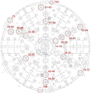
Figure 2, the shield cutterhead employs a 6-main-spoke + 6-auxiliary-spoke atmospheric pressure structure with an opening ratio of 27%. The panel material is S355 steel with a thickness of 200 mm, surfaced with 20 mm wear-resistant composite plate. The cutter housings and cutter box protection rings are likewise fabricated from S355 material. A total of 39 cutter housings are configured, comprising center cutters, face cutters, and gauge cutters.
After 39.7 m of tunneling, the shield was stopped for inspection, revealing typical hard rock abrasion damage characteristics on the cutterhead. As illustrated in
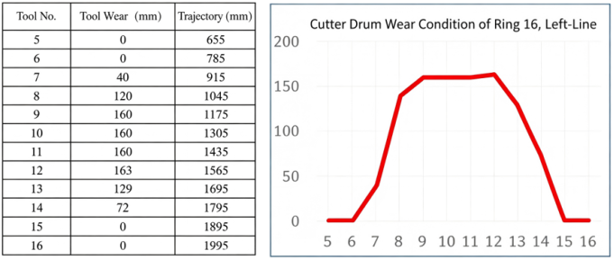
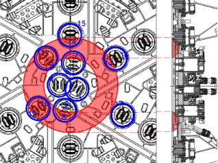
Figure 3, cutter housings No. 5 through No. 16 exhibited widespread wear, with a maximum wear depth of 163 mm. Six cutter housings experienced seal failure, and the cutter box protection rings exhibited a maximum wear depth of 120 mm, with wear extending to the seal mating surface at several locations. As shown in
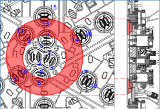
Figure 4, the central region of the cutterhead panel exhibited a maximum wear depth of 43 mm, with the wear pattern diminishing progressively from the center toward the periphery. Additionally, three central flushing ports and the wear detection pipelines all sustained abrasive damage. The temperature in the central region of the cutterhead reached up to 80°C, indicating a significant risk of overheating-related wear.
Figure 1. Geological Longitudinal Profile.
Figure 2. Initial tool layout of S1046.
Figure 3. Tool wear inspection of the 16th ring on the left line.
Figure 4. Cutterhead and panel wear of the 16th ring on the left line.
3. Overall Repair Strategy and Construction Process
Based on the stratum self-stabilization capacity and the confirmed atmospheric pressure access conditions, this project adopted an in-situ repair scheme combining atmospheric pressure access with manual chamber excavation. Specifically, an arched working chamber was manually excavated at the tunnel face, stabilized by wire-mesh-reinforced shotcrete support to create a safe working environment. Repair operations then proceeded in a graded sequence prioritizing severity—cutter boxes first, followed by the panel—encompassing the repair of cutter boxes, cutter housings, the cutterhead panel, and auxiliary pipelines. Upon completion of weld inspection, pressure-holding tests, and chamber backfilling, trial tunneling was conducted. Normal tunneling resumed after acceptance verification.
The overall construction was organized and executed in accordance with the principles of continuity, controllability, and safety, proceeding sequentially through the following stages: construction preparation and technical briefings; staged depressurization of the slurry chamber to atmospheric pressure with confirmation of face stability; excavation and support of the repair chamber; graded repair of cutter boxes; cutterhead panel welding reinforcement and flatness control; repair or replacement of cutter housings with seal upgrading; replacement welding of flushing ports and wear detection pipelines; dye penetrant inspection of welds and quality acceptance; cutter reinstallation and trajectory verification; chamber cleanout and backfill consolidation; pressure-holding tests and system commissioning; trial tunneling and parameter optimization; and ultimately, resumption of normal tunneling. Quality and safety control were rigorously enforced throughout all stages
| [7] | Su, W., Li, X., Jin, D., Yang, Y. Analysis and prediction of TBM disc cutter wear when tunneling in hard rock strata: A case study of a metro tunnel excavation in Shenzhen, China [J]. Wear, 2020, 446?447: 203190.
https://doi.org/10.1016/j.wear.2020.203190 |
| [12] | Wu, Y., Yang, H., Zhang, H., Hou, Y., Yang, S. Real?time prediction of tunnel boring machine thrust based on multi?resolution analysis and online learning [J]. Computer?Aided Civil and Infrastructure Engineering, 2025, 40(28): 5212?5227.
https://doi.org/10.1111/mice.70096 |
[7, 12]
. The entire construction process was conducted in strict compliance with the relevant specifications for confined space operations
| [3] | Safety Technical Specification for Confined Space Operation: DB33/T 707-2008(2013) [S]. Hangzhou: Zhejiang Provincial Bureau of Quality and Technical Supervision, 2013. |
[3]
.
4. Key Repair Technologies and Solutions
4.1. Cutterhead Repair
4.1.1. Cutter Box Repair
(1) Repair of Cutter Boxes No. 5–7
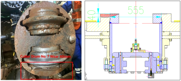
① Wear condition (cutter box seal not worn): The cutter box protection ring exhibited a maximum wear depth of 40 mm, with the worn region extending approximately 80 mm in length, as shown in
Figure 5.
② Repair scheme: 1) The irregular worn areas of the cutter box protection ring were ground smooth and bright using an angle grinder. 2) Given the relatively minor wear on cutter boxes No. 5–7 and No. 14–16, overlay welding was applied to the ground wear regions using the cutter housing as the positioning reference. 3) After completion of buildup welding on the cutter housing protection ring, the inner bore of the cutter box protection ring was ground to a tolerance of ±0.3 mm. A pressure holding test was conducted upon completion of the cutter box repair.
(2) Repair of Cutter Boxes No. 6–8, No. 13–15, and No. 14–16
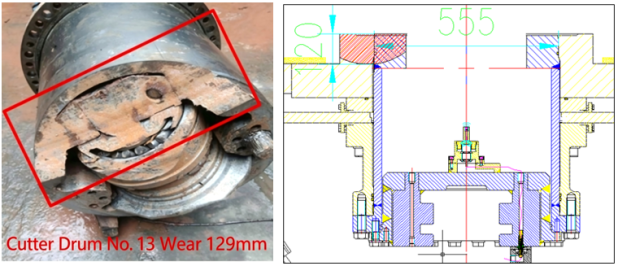
① Wear condition (cutter box seal worn; panel not worn): Cutter boxes No. 6–8: Maximum cutter housing wear of 120 mm; no panel wear; cutter box protection ring maximum wear of 120 mm; No. 6 disc cutter exhibited 2 mm of wear, and the cutter ring of No. 8 disc cutter was worn off. Cutter boxes No. 13–15: As shown in
Figure 6, maximum eccentric wear of the cutter housing was 129 mm; panel wear was 9 mm; cutter box protection ring maximum wear was 120 mm; the cutter ring of No. 13 disc cutter was worn off, and No. 15 disc cutter exhibited 40 mm of eccentric wear. Cutter boxes No. 14–16: Maximum eccentric wear of the cutter housing was 72 mm; no panel wear; cutter box protection ring wear was 72 mm; No. 14 and No. 16 disc cutters exhibited no wear.
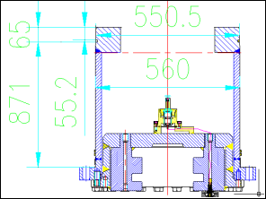
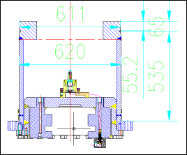
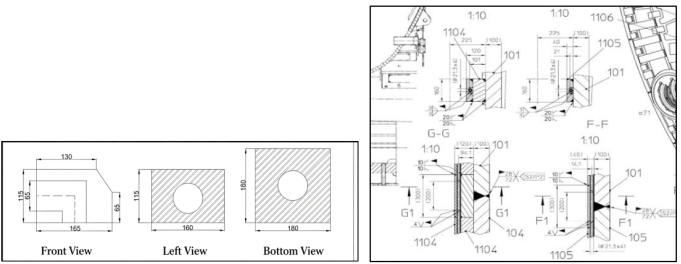
② Repair scheme: 1) Externally fabricated cutter box protection rings were procured, manufactured from S355 steel with a thickness of 100 mm, an inner diameter of 551 mm (cutter housing outer diameter of 555 mm, providing 2 mm clearance on each side), and an outer diameter of 856 mm. A 45° bevel was machined on the welding surface. Concurrently, positioning fixtures for the center cutter housing and face disc cutter housing were fabricated using used cutter housings, as illustrated in
Figures 7 and 8 respectively. 2) The original cutter box protection ring was completely removed by gouging and the surface ground smooth and bright. 3) The corresponding positioning fixture was installed and employed as the positioning reference for welding the new cutter box protection ring. 4) Upon completion of welding, the positioning fixture was removed. Using the bolt holes of the gate cutter housing as the positioning center, the boring equipment was installed and its centrality verified. 5) After confirming accurate positioning of the boring equipment, boring of the cutter box protection ring commenced. The clearance fit between the cutter housing and the cutter box protection ring was controlled within 0.15–0.25 mm. 6) A pressure holding test was conducted upon completion of the cutter box repair.
(3) Repair of Cutter Boxes No. 9–11 and No. 10–12
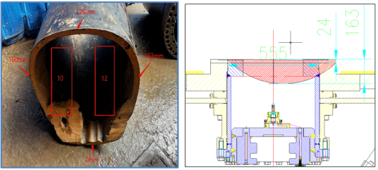
① Wear condition (seal and panel worn): Cutter boxes No. 9–11: Maximum cutter housing wear of 160 mm; panel wear of 40 mm; cutter box protection ring wear of 120 mm; the cutter rings of both No. 9 and No. 11 disc cutters were worn off. Cutter boxes No. 10–12: As shown in
Figure 9, maximum cutter housing wear of 163 mm; maximum panel wear of 43 mm; cutter box protection ring wear of 120 mm; the cutter rings of both No. 10 and No. 12 disc cutters were worn off.
② Repair scheme: 1) Externally fabricated cutter box protection rings were procured, manufactured from S355 steel with a thickness of 100 mm, an inner diameter of 551 mm (cutter housing outer diameter of 555 mm, providing 2 mm clearance on each side), and an outer diameter of 856 mm, with a 45° bevel machined on the welding surface. 2) The worn area of the cutter box panel was ground smooth and bright; after grinding, overlay welding was performed using the cutter housing as the positioning reference. 3) Upon completion of overlay welding, the inner bore of the cutter box was ground, with the clearance fit controlled within 0.3–0.5 mm. 4) The worn region of the cutter box protection ring was completely removed by gouging and the surface ground smooth and bright. 5) The positioning fixture was installed and used as the reference for welding the new cutter box protection ring. 6) After welding of the cutter box protection ring was complete, the positioning fixture was removed. The boring equipment was installed using the gate cutter housing bolt holes as the positioning center, and its centrality was verified. 7) After confirming accurate positioning, boring of the cutter box protection ring commenced, with the clearance fit between the cutter housing and the cutter box protection ring controlled within 0.3–0.5 mm. 8) A pressure holding test was conducted upon completion of the cutter box repair.
Figure 5. Tool wear of No. 5–7.
Figure 6. Tool wear of No. 13–15 (maximum wear).
Figure 7. Tooling drawing of center cutter.
Figure 8. Tooling drawing of front hob.
Figure 9. Tool wear of No. 10–12 (maximum wear).
4.1.2. Panel Repair
(1) Wear condition: The wear of the cutterhead panel diminished progressively from a maximum depth of 43 mm at the center toward both sides, as schematically illustrated in
Figure 10.
(2) Repair scheme: ① The worn areas of the cutterhead panel were ground to a regular and bright surface. ② The dimensions of the ground wear areas were measured, and prefabricated steel plates of the same material were externally machined to shape. ③ The machined steel plates were welded to the parent material and reinforced with rivet welding; the welding surfaces were beveled. ④ Unfilled recesses were treated by overlay welding; after welding, the surface was ground, with the flatness of the cutterhead panel controlled within ±5 mm. ⑤ Upon completion of panel welding, dye penetrant inspection was performed to ensure weld quality.
Figure 10. Schematic diagram of panel wear.
4.1.3. Wear Detection and Flushing Port Pipeline Repair
(1) According to on-site inspection, three central flushing ports and two wear detection circuits of the cutterhead had sustained abrasive damage.
(2) Wear detection blocks and central flushing ports were externally fabricated from S355 steel, as shown in the machining drawing in
Figure 11.
(3) The damaged flushing ports and hydraulic wear detection zones were ground to a regular, clean surface using an angle grinder and an air carbon-arc gouging torch.
(4) In accordance with the cutterhead drawings, the prefabricated flushing ports and hydraulic wear detection blocks were welded at the designated positions. The orientation of the flushing ports was verified to prevent installation errors.
(5) Upon completion of welding, dye penetrant inspection was performed on all welds to ensure weld quality. The hydraulic circuit of the wear detection system was pressurized to 150 bar, with the requirement that the pressure drop over a 20-minute period not exceed 0.1 bar.
Figure 11. Processing drawing of flushing port and hydraulic wear pipe.
4.1.4. Weld Inspection Requirements and Standards
(1) During the cutterhead repair welding process, the project team rigorously conducted inspections in accordance with weld inspection standards and the prepared weld quality inspection and acceptance forms. Non-conforming welds identified during the process were completely gouged out and re-welded, with secondary inspection mandatory; any weld failing to meet the acceptance criteria was prohibited from proceeding to the subsequent work stage. The base material was required to be preheated to 180°C prior to welding. Upon completion of all repair welding for each cutter box, the project department performed self-inspection using dye penetrant testing.
(2) The surface quality evaluation of CO₂ gas-shielded welding primarily concerns the assessment of weld appearance, requiring uniform weld beads free from defects such as incomplete fusion, spatter, slag inclusions, cracks, burn-through, shrinkage cavities, and undercut. Additionally, the quantity, length, and position of welds must conform to the process specifications.
4.2. Damaged Cutter Housing Repair
(1) Wear condition: A total of six cutter housings were removed. The front-end seals of cutter housings No. 5–7 and No. 14–16 remained intact, whereas the remaining four cutter housings (No. 6–8, No. 9–11, No. 10–12, and No. 13–15) all sustained damage to the front-end seals as a result of wear.
(2) Repair measures: The three most severely damaged center cutter housings (No. 6–8, No. 9–11, and No. 10–12) were re-manufactured by the manufacturer (expected on-site delivery date: January 15). The remaining three cutter housings (No. 5–7, No. 13–15, and No. 14–16) were sent out for repair by means of build-up welding. Repair was expected to be completed by January 10, 2023. Depending on the on-site assessment of cutter housing seal integrity, an upgrade to a double-seal configuration was considered where warranted. The repair schedule is detailed in
Table 1.
Table 1. Repair cycle schedule.
No. | Cutter housing No. | Wear degree | Repair cycle (days) | Expected arrival date | Remarks |
1 | 5-7# | Front seal intact | 10 | 2023.1.10 | |
2 | 14-16# | Front seal intact | 10 | 2023.1.10 | |
3 | 13-15# | Seal slightly damaged | 10 | 2023.1.10 | |
4 | 6-8# | Seal fully damaged | 15 | 2023.1.15 | |
5 | 9-11# | Seal fully damaged | 15 | 2023.1.15 | |
6 | 10-12# | Seal fully damaged | 15 | 2023.1.15 | |
4.3. Gate and Cutterhead Seal Inspection
During the cutter box repair period, the cutter housing gates within the wear-affected range were dismantled for inspection. Damaged seals were replaced immediately if identified. Additionally, the seals between the gates and the cutterhead panel were replaced.
5. Experiments and Results
5.1. Cutter Reinstallation and Pressure Holding Tests
(1) Upon completion and acceptance testing of the cutterhead panel and cutter box repairs, reinstallation of the cutters and gates commenced. During reinstallation, careful positioning was performed to avoid alignment errors that could result in incorrect cutter installation.
(2) As presented in
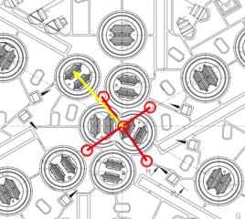
Table 2, the trajectories of all cutters were verified at the front face of the cutterhead after installation to ensure accuracy. Trajectory verification method: As shown in
Figure 12, the center point was determined using a total station referenced to four positioning points on the cutterhead panel, and the cutter trajectory dimensions were subsequently verified against this center.
Table 2. Tool track of No. 5–16.
No. | Tool No. | Track (mm) |
1 | 5# | 655 |
2 | 6# | 785 |
3 | 7# | 915 |
4 | 8# | 1045 |
5 | 9# | 1175 |
6 | 10# | 1305 |
7 | 11# | 1435 |
8 | 12# | 1565 |
9 | 13# | 1695 |
10 | 14# | 1795 |
11 | 15# | 1895 |
12 | 16# | 1995 |
Figure 12. Center positioning drawing of cutterhead.
5.2. Trial Tunneling and Normal Section Tunneling
5.2.1. Trial Tunneling Acceptance
(1) Personnel entered the slurry chamber through the slurry gate to perform cleanout. The residual liquid level in the chamber was drained via the bottom advance grouting holes, and standing water in the tunnel was pumped to the working shaft using a 7.5 kW pump. After drainage, debris including detached cutter rings within the chamber was retrieved.
(2) The slurry chamber pressure was reduced to atmospheric level. The repair chamber was backfilled with a dry mixture of sand and cement; after every 0.5 m of fill, the fill material was moistened to facilitate consolidation until backfilling was complete.
(3) Chamber pressurization was initiated, slurry circulation was established, and the cutterhead rotation speed was controlled at 0.1–0.2 rpm to trim the tunnel face evenly and ensure the complete removal of residual muck from the slurry chamber.
(4) Acceptance was conducted with reference to
Table 3. Trial tunneling could commence only after all acceptance criteria were satisfied. The entire acceptance procedure strictly adhered to the shield tunnel construction acceptance specifications
| [1] | Code for Construction and Acceptance of Shield Tunneling: GB 50446-2017 [S]. Beijing: China Architecture & Building Press, 2017. |
[1]
.
Table 3. Inspection and acceptance before trial tunneling,
Acceptance item | Acceptance key points |
Cutterhead | Does the post-repair dye penetrant test report meet requirements? Are the cutter trajectories consistent with the drawings? Are the gate seal seat positions correct? |
Tunnel face | Has the truss support on the tunnel face been cut and completely removed? Have all cutterhead attachments been cleaned? |
Repair chamber | Has the repair chamber been completely backfilled? |
Air cushion chamber | Has the rock crusher been re-commissioned and tested? Has the slurry gate been re-commissioned and tested? Have foreign objects been cleared from the air cushion chamber and slurry chamber? Has the air cushion chamber passed re-pressurization testing? Have the tee joints and bends of through-chamber pipelines been reinforced (wrapped/repaired)? |
Cutter monitoring | Is the cutter monitoring system functioning normally, with rotation, temperature, and wear readings correctly displayed on the host computer? |
Personnel training | Have the chief operator and duty engineer received re-training and technical briefing on chamber pressurization safety? |
5.2.2. Trial Tunneling Parameters
The trial tunneling segment corresponded to the 16th ring. The parameter control during tunneling was as follows: pressure at the top of the slurry chamber was maintained at 1–1.05 bar, with pressure fluctuation not exceeding ±0.05 bar; cutterhead rotation speed was 0.8–1 rpm; penetration rate was 1–3 mm/rev; torque ranged from 3,000 to 4,500 kN·m with a fluctuation range not exceeding 1,200 kN·m; thrust was governed by the advancement speed requirement and did not exceed 6,000 t. Cutter housing bolts were inspected once at 0.2 m and once at 0.5 m of advance. The tunneling parameter settings referenced the construction standards for underground railway engineering
| [2] | Standard for Construction and Acceptance of Metro Engineering: GB/T 50299-2018 [S]. Beijing: China Planning Press, 2018. |
[2]
.
5.2.3. Resumption of Normal Tunneling
Upon completion of trial tunneling, with all tunneling parameter fluctuations confirmed to be within the specified ranges, normal section tunneling was resumed. The parameter control requirements for normal section tunneling were as follows: pressure at the top of the slurry chamber was maintained at 1–1.05 bar, with pressure fluctuation not exceeding ±0.05 bar; cutterhead rotation speed was 1 rpm; penetration rate was 3–5 mm/rev; torque ranged from 3,000 to 4,500 kN·m, with a fluctuation range not exceeding 1,200 kN·m; thrust was governed by the advancement speed requirement and did not exceed 6,000 t; the squeezing force was controlled within 800–1,200 t. Cutter housing bolts were inspected once after the completion of each ring of advance.
6. Conclusions
(1) In hard rock strata with favorable self-stabilization characteristics such as moderately weathered quartz sandstone, the combined approach of atmospheric pressure access and manual chamber excavation enables the safe completion of in-situ repair of large-diameter shield cutterheads. This technology is characterized by strong applicability, high safety and reliability, and significant economic benefits, and can be promoted for use in urban core areas, cultural relic protection zones, and densely built districts.
(2) The graded repair of cutter boxes, panel welding reinforcement, non-destructive testing of welds, pressure-holding tests, and refined control of trial tunneling parameters collectively constitute a repair quality assurance system, which is key to ensuring the long-term stable operation of the cutterhead after repair. The risk prevention and control system—centered on stratum stability control, reliable chamber support, whole-process monitoring and early warning, and confined space safety management—effectively guarantees construction safety and the stability of the surrounding environment.
(3) To further optimize the service performance and repair outcomes of shield cutterheads in hard rock strata, it is recommended that cutter configuration and tunneling parameters be optimized during the excavation phase to reduce abnormal cutterhead wear at the source. High-performance wear-resistant materials and enhanced welding processes should be preferentially adopted in repair operations to improve structural durability and wear resistance. Concurrently, an online cutterhead wear monitoring system should be established to enable early wear warning and proactive maintenance, thereby extending the service life of the cutterhead.
Author Contributions
Gu Tianxin: Conceptualization, Methodology, Investigation, Writing – original draft
Wang Kai: Formal analysis, Data curation, Visualization
Chen Qiao: Resources, Validation
Wan Xueyu: Supervision, Project administration, Writing – review & editing
Bao Peng: Investigation, Software
Conflicts of Interest
The authors declare no conflicts of interest.
References
| [1] |
Code for Construction and Acceptance of Shield Tunneling: GB 50446-2017 [S]. Beijing: China Architecture & Building Press, 2017.
|
| [2] |
Standard for Construction and Acceptance of Metro Engineering: GB/T 50299-2018 [S]. Beijing: China Planning Press, 2018.
|
| [3] |
Safety Technical Specification for Confined Space Operation: DB33/T 707-2008(2013) [S]. Hangzhou: Zhejiang Provincial Bureau of Quality and Technical Supervision, 2013.
|
| [4] |
Chen J. Research on disc cutter and gear cutter replacement technology for large diameter slurry shield under atmospheric pressure in composite strata [J]. Tunnel Construction, 2018, 38(S1): 175-181.
|
| [5] |
Chen, J., Min, F. L. Shield Tunnel Cutter Replacement Technology [M]. Singapore: Springer, 2022.
|
| [6] |
Li, X. G., Yuan, D. J. Creating a working space for modifying and maintaining the cutterhead of a large?diameter slurry shield: A case study of Beijing railway tunnel construction [J]. Tunnelling and Underground Space Technology, 2018, 72: 73?83.
https://doi.org/10.1016/j.tust.2017.11.008
|
| [7] |
Su, W., Li, X., Jin, D., Yang, Y. Analysis and prediction of TBM disc cutter wear when tunneling in hard rock strata: A case study of a metro tunnel excavation in Shenzhen, China [J]. Wear, 2020, 446?447: 203190.
https://doi.org/10.1016/j.wear.2020.203190
|
| [8] |
Wang, Y.?N., Chen, H., Min, X.?H., Zhao, L.?S. Identification of disc cutter wear via operation parameters combined with vibration data: A case study [J]. International Journal for Numerical and Analytical Methods in Geomechanics, 2025, 49(1): 256?279.
https://doi.org/10.1002/nag.3872
|
| [9] |
Ning, B., Li, M., Long, S., Yang, M. Failure analysis of a tunnel boring machine cutter holder system [J]. Proceedings of the Institution of Mechanical Engineers, Part C: Journal of Mechanical Engineering Science, 2026, 240(6): 2145?2158.
https://doi.org/10.1177/09544062251407041
|
| [10] |
Pu, X., Jia, L., Shang, K., Chen, L., Yang, T., Chen, L., Gao, L., Qian, L. A new strategy for disc cutter wear status perception using vibration detection and machine learning [J]. Sensors, 2022, 22(17): 6686.
https://doi.org/10.3390/s22176686
|
| [11] |
Elbaz, K., Shen, S.?L., Zhou, A.?N., Lyu, H.?M. Prediction of disc cutter life during shield tunneling with AI via the incorporation of a genetic algorithm into a GMDH?type neural network [J]. Engineering, 2021, 7(2): 238?251.
https://doi.org/10.1016/j.eng.2020.02.016
|
| [12] |
Wu, Y., Yang, H., Zhang, H., Hou, Y., Yang, S. Real?time prediction of tunnel boring machine thrust based on multi?resolution analysis and online learning [J]. Computer?Aided Civil and Infrastructure Engineering, 2025, 40(28): 5212?5227.
https://doi.org/10.1111/mice.70096
|
| [13] |
Fu, T., Zhang, T., Song, X. A novel hybrid transfer learning framework for dynamic cutterhead torque prediction of the tunnel boring machine [J]. Energies, 2022, 15(7): 2907.
|
| [14] |
Cardu, M., Farzay, O., Almeida, N. D. M., Todaro, C. The challenge of tool consumption prediction in TBM excavation: The micro?hardness approach [J]. Geomechanics and Tunnelling, 2025, 19(1): 109?119.
https://doi.org/10.1002/geot.70045
|
| [15] |
Su, Y., Wang, S., Xia, Y. Cutting Performance and Contact Behavior of Partial?Wear TBM Disc Cutters: A Laboratory Scale Investigation [J]. Engineering Failure Analysis, 2022, 137: 106253.
https://doi.org/10.1016/j.engfailanal.2022.106253
|
Cite This Article
-
APA Style
Tianxin, G., Kai, W., Qiao, C., Xueyu, W., Peng, B. (2026). Key Technologies for Cutterhead Repair of Large-Diameter Slurry Balance Shield Under Atmospheric Pressure Access. Journal of Civil, Construction and Environmental Engineering, 11(5), 264-273. https://doi.org/10.11648/j.jccee.20261105.12
 Copy
|
Copy
|
 Download
ACS Style
Tianxin, G.; Kai, W.; Qiao, C.; Xueyu, W.; Peng, B. Key Technologies for Cutterhead Repair of Large-Diameter Slurry Balance Shield Under Atmospheric Pressure Access. J. Civ. Constr. Environ. Eng. 2026, 11(5), 264-273. doi: 10.11648/j.jccee.20261105.12
Copy
|
Download
AMA Style
Tianxin G, Kai W, Qiao C, Xueyu W, Peng B. Key Technologies for Cutterhead Repair of Large-Diameter Slurry Balance Shield Under Atmospheric Pressure Access. J Civ Constr Environ Eng. 2026;11(5):264-273. doi: 10.11648/j.jccee.20261105.12
Copy
|
Download
-
@article{10.11648/j.jccee.20261105.12,
  author = {Gu Tianxin and Wang Kai and Chen Qiao and Wan Xueyu and Bao Peng},
  title = {Key Technologies for Cutterhead Repair of Large-Diameter Slurry Balance Shield Under Atmospheric Pressure Access},
  journal = {Journal of Civil, Construction and Environmental Engineering},
  volume = {11},
  number = {5},
  pages = {264-273},
  doi = {10.11648/j.jccee.20261105.12},
  url = {https://doi.org/10.11648/j.jccee.20261105.12},
  eprint = {https://article.sciencepublishinggroup.com/pdf/10.11648.j.jccee.20261105.12},
  abstract = {Aiming at the common engineering challenges of severe wear, eccentric wear, and seal failure of cutterheads during the excavation of large-diameter shields in hard rock strata, this study investigates the in-situ cutterhead repair technology under atmospheric pressure access conditions, based on the cutterhead damage repair project of the φ15.01 m slurry balance shield on the left line of the Zhijiang Road Water Conveyance Pipe Gallery and Road Improvement Project in Hangzhou. Through stratum stability assessment, verification of atmospheric pressure access conditions, excavation and support of working chambers, staged repair of cutter boxes, panel welding reinforcement, non-destructive testing of welds, pressure-holding tests, and trial tunneling parameter control, a complete set of repair technologies applicable to large-diameter shield cutterhead repair under atmospheric pressure in moderately weathered hard rock strata has been developed. Engineering practice demonstrates that this approach enables rapid cutterhead repair without the need for additional excavation or equipment disassembly, with repair accuracy meeting design requirements. Throughout the construction process, ground surface settlement and deformation of buildings and structures remain within controllable limits, effectively ensuring the safety of adjacent cultural relic buildings and existing pipelines. The research results provide technical references for the treatment of cutterhead damage in large-diameter shields constructed in hard rock strata within urban core areas.},
 year = {2026}
}
Copy
|
Download
-
TY  - JOUR
T1  - Key Technologies for Cutterhead Repair of Large-Diameter Slurry Balance Shield Under Atmospheric Pressure Access
AU  - Gu Tianxin
AU  - Wang Kai
AU  - Chen Qiao
AU  - Wan Xueyu
AU  - Bao Peng
Y1  - 2026/09/22
PY  - 2026
N1  - https://doi.org/10.11648/j.jccee.20261105.12
DO  - 10.11648/j.jccee.20261105.12
T2  - Journal of Civil, Construction and Environmental Engineering
JF  - Journal of Civil, Construction and Environmental Engineering
JO  - Journal of Civil, Construction and Environmental Engineering
SP  - 264
EP  - 273
PB  - Science Publishing Group
SN  - 2637-3890
UR  - https://doi.org/10.11648/j.jccee.20261105.12
AB  - Aiming at the common engineering challenges of severe wear, eccentric wear, and seal failure of cutterheads during the excavation of large-diameter shields in hard rock strata, this study investigates the in-situ cutterhead repair technology under atmospheric pressure access conditions, based on the cutterhead damage repair project of the φ15.01 m slurry balance shield on the left line of the Zhijiang Road Water Conveyance Pipe Gallery and Road Improvement Project in Hangzhou. Through stratum stability assessment, verification of atmospheric pressure access conditions, excavation and support of working chambers, staged repair of cutter boxes, panel welding reinforcement, non-destructive testing of welds, pressure-holding tests, and trial tunneling parameter control, a complete set of repair technologies applicable to large-diameter shield cutterhead repair under atmospheric pressure in moderately weathered hard rock strata has been developed. Engineering practice demonstrates that this approach enables rapid cutterhead repair without the need for additional excavation or equipment disassembly, with repair accuracy meeting design requirements. Throughout the construction process, ground surface settlement and deformation of buildings and structures remain within controllable limits, effectively ensuring the safety of adjacent cultural relic buildings and existing pipelines. The research results provide technical references for the treatment of cutterhead damage in large-diameter shields constructed in hard rock strata within urban core areas.
VL  - 11
IS  - 5
ER  -
Copy
|
Download





 Share This Article
 Twitter
 Linked In
 Facebook