Research Article | | Peer-Reviewed

Energy Analysis of a Thermodynamic System Combined Organic Rankine Cycle and Absorption Cooling System for Power and Cooling: Effects of Pressure and Temperature

Received: 18 January 2025     Accepted: 3 February 2025     Published: 20 February 2025
Views:       Downloads:
Abstract

In the current economic, energy and environmental context, the implementation of technologies using renewable energies as a source of power electricity and cooling production is very beneficial insofar as it allows the reduction of pollution and the cost of fossil fuels. Senegal has a sunshine potential well distributed across the country for irradiation varying from South to North between 1850 KWh/m²/year and 2250 kWh/m²/year. It is one of the best solar potentials in the world. Systems operating on the organic Rankine cycle ORC and the absorption cooling system ACS are innovative and sustainable technologies for the exploitation of low enthalpy renewable energy sources. In this present work, the thermodynamic analysis of a combined ORC and ACS system for power electricity and cold production is carried out numerically using the Engineering Equation Solver (EES) software. R245fa and water-lithium bromide mixture are used as working fluid for ORC and ACS respectively. The results obtained at the ACS subsystem level show that the COP of ACS decreases when the absorption temperature increases. This reduction goes from 0.83 to 0.55, i.e. a reduction of 0.28 for a variation of absorption temperature from 27°C to 45°C. The COP has stabilized for generator temperatures above 95°C and is in the range of 0.7 to 0.8. These fluctuations are due to the irreversibility at the level of the components of the system. For the ORC subsystem, the turbine power and ORC condenser power decrease as the ORC condensing pressure increases. Thus, the turbine power goes from 235 kW to 200 kW and the ORC condenser power goes from 80 kW to 60 kW.

Published in International Journal of Sustainable and Green Energy (Volume 14, Issue 1)
DOI 10.11648/j.ijsge.20251401.14
Page(s) 42-52
Creative Commons

This is an Open Access article, distributed under the terms of the Creative Commons Attribution 4.0 International License (http://creativecommons.org/licenses/by/4.0/), which permits unrestricted use, distribution and reproduction in any medium or format, provided the original work is properly cited.

Copyright

Copyright © The Author(s), 2025. Published by Science Publishing Group

Keywords

Power Electricity, Organic Rankine Cycle, Absorption Cooling System, Thermodynamic, Analysis

1. Introduction
The energy transition resulting from limiting the use of fossil fuel resources and reducing greenhouse gas (GHG) emissions is the basis of numerous studies and applications on renewable energies. The combination of the Organic Rankine Cycle (ORC) and the absorption cooling system (ACS) for the combined power and cooling is very promising insofar as it allows the use of renewable energy sources such as solar, geothermal, biomass and waste heat from industrial processes gases or internal combustion engines. Organic Rankine Cycle is a special type of Rankine cycle that uses an organic fluid as the working fluid instead of water. Given that the boiling point of organic fluid is lower than that of water, the ORC cycle can be used with various types of low temperature heat sources such as geothermal energy, solar energy, biomass energy and waste heat. The Rankine cycle or steam Rankine cycle is a process widely used in power plants such as coal power plants or nuclear reactors. In this mechanism, a fuel is used to produce heat inside a boiler, transforming water into steam which then expands through a turbine producing useful work. Unlike these Rankine cycles used in large power plants with a power greater than 50 MWe with a high temperature hot source available, organic Rankine cycles allow the recovery of low temperature heat, less than 300°C. ORC cycles have four main classes of applications which are geothermal, biomass, solar energy and industrial processes. These applications represent the majority of achievements in terms of installed power and number of installations . Geothermal energy is the exploitation of heat stocks contained in the earth's crust, to produce heat and electricity. The technological lower limit for electricity production is around 80°C. Below this temperature, the conversion efficiency becomes too low and geothermal power plants will not be economical . The binary power cycle can be beneficial in the case of low-temperature geothermal reservoirs by activating the ORC or the Kalina cycle . Wenge et al., developed a geothermal heating and power generation system that transfers heat using Organic Rankine Cycle and radiant underfloor heating technologies. Their results show that increasing the temperature of the working fluid and the inlet pressure of the ORC turbine reduces the capacity of the Organic Rankin Cycle turbine and increases the heat. A new integrated system that uses geothermal energy as a renewable energy source is introduced by Ozturk and Dincer . An ORC-based hybrid solar-geothermal power generation system is developed by D. Li et al., for sites where the solar resources are different, and the geothermal water temperature is below 100°C. Their system utilizes geothermal water for preheating the organic working fluid and solar energy for superheating. Energy, exergy and economic (3E) analysis of a two-stage organic Rankine cycle for single flash geothermal power plant exhaust exergy recovery was carried out by G. Fan et al., . In their study, the impact of essential design parameters such as inlet temperature of the cycle, ambient temperature, geothermal turbine inlet pressure, geothermal condensation temperature on system performance are investigated using thermodynamic mathematical models regarding energy and exergy efficiencies. E. Assareh et al., researches focused on the modeling and optimization of an innovative geothermal system utilizing a modified Organic Rankine Cycle (ORC) for the production of electricity, H2, cooling, and heating. Their results showed that the study system can produce 3,982,413.6 kWh of heating, and 4,555,440 kWh of cooling during the year.
Biomass is widely available in a number of agricultural or industrial processes such as the wood industry and agricultural waste. Among other means, it can be converted into heat through combustion and into electricity through a thermodynamic cycle. Most ORC systems for biomass are binary cycles . Most often, energy recovery for this type of plant is limited to 6 MWth to 10 MWth, i.e. an electrical production of 1 MW to 2 MW. Therefore, in order to achieve high energy conversion efficiency, biomass cogeneration power plants are generally driven by heat demand rather than electricity demand.
The majority of biomass systems incorporate ORC . By utilizing the ORC, biomass that has been converted to heat via combustion can have its heat converted back into electricity . A small-scale ORC, suitable for a Combined Cooling and Power (CCHP) application, through an absorption chiller, that uses biomass renewable energy as heat source is carried out by Joaquín Navarro-Esbrí et al., . An investigation into the exergy-economic analysis of a hybrid combined supercritical Brayton cycle-organic Rankine cycle using biogas and solar PTC system as energy sources was carried out by A. Alghamdi et al., . Solar energy is the most abundant source of energy. In concentrated solar power plants, solar radiation is directed towards a collector via heliostats, which allows the heat transfer fluid to be heated. The transferred heat is then recovered in a thermodynamic cycle to generate electricity. A suitable heat transfer fluid, usually synthetic oil, is used in solar collectors. The nature of the ORC cycle or the Rankine cycle depends on the temperature of the heat transfer fluid and therefore on the technology used. Solar towers, parabolic collectors, parabolic trough collectors and Fresnel collectors are the main solar concentrating technologies . In punctual concentrations, the temperature of the heat transfer fluid can reach 1000°C, which means that ORC technology is not applicable. On the other hand, in linear concentration power plants, temperatures do not exceed 400°C. It is therefore entirely possible to use an ORC as an electricity generation system, particularly in small solar fields or with little sunlight . In addition, these power plants are less expensive than punctual collection power plants. The disadvantage of solar energy is its intermittent nature which causes an imbalance between consumer demand and availability of the heat source. The addition of thermal energy storage is considered to shift excess energy from periods of high insolation to nighttime periods or periods of unfavorable conditions. These solutions increase efficiency, reliability and flexibility of the system. An interesting application of ORCs combined with solar energy is standalone configuration in remote areas, for end users not connected to the electricity grid. Concentrated Solar Power (CSP) coupled with Organic Rankine Cycle (ORC) systems offers a promising approach for sustainable electricity and heat generation . The results will pave the way for optimizing CSP-ORC systems and promoting their adoption as a clean and efficient renewable energy technology, contributing to a low-carbon future. Organic Rankine Cycle (ORC) is a widely recognised technology to convert solar heat into power with high reliability and low cost . A novel cogeneration system which combines a compressed air storage system, an organic Rankine cycle system and a solar collector system is proposed by Y. Li et al., . Their hybrid system is examined in terms of energy, exergy, and economics. Pilot testing of 10 kW capacity of Linear Fresnel collector-Organic Rankine Cycle process under arid and desert conditions of Arabian Gulf operating conditions (Qatar) is carried out by J. Jawad et al., . In their study, the system Linear Fresnel collector-Organic Rankine Cycle operations at storage temperatures of 170°C showed peak electricity production of 6.76 kW for 38 W/m2 aperture area of Linear Fresnel collector whereas 1st law, and 2nd law efficiencies were 6 % and 19 %, respectively. Energy, exergy and economic analyses of a new ORC system based on Linear Fresnel Reflector system to generate electrical energy are carried out by K. Sun, T. Zhao, S. Wu et al., . In their process, the solar system provides the required heat duty of the evaporator of ORC system. N. Khani et al., introduce a new design and dynamic simulation approach to a solar energy-driven polygeneration system integrating gas and steam turbine cycles, organic Rankine cycle (ORC), CO2 capture, and humidification dehumidification (HDH) desalination. The results obtained reveal that solar energy integration boosts ORC’s power generation from 37.3% (winter) to 59.41% (summer), while the overall power production increases by 18 kW compared to the base case scenario. In many industrial processes, a significant amount of heat is released into the atmosphere at a temperature below 350°. In addition to being lost, this causes several types of pollution. The recovery of industrial waste heat therefore has a double challenge, economic and environmental. It can also produce electricity which will be consumed on site or reinjected into the electricity network . Moreira and Arrieta made comparison studies between ORC and other waste heat recovery technologies, such as Stirling engine, thermoelectricity and Brighton reverse cycle. The results revealed that ORC is the most efficient technology for heat recovery and power generation from heat sources at temperatures between 200°C and 400°C. The working fluid receives heat from the exhaust gas in the constant pressure evaporator unit and undergoes isentropic expansion in the turbine . On average, one third of the energy generated by fuel is lost in the exhaust gases of a typical internal combustion engine. Using this solution, the power output can be increased by 3% if heat is simply recovered from the water jacket and by 10% if heat from high temperature flue gases is used . Another area of increasing interest in recent years is the use of ORC coupled with diesel engines. The road transport sector, mainly powered by heavy diesel engines, was estimated to account for 14% of global greenhouse gas emissions in 2014 . They release a large quantity of heat into the environment since the efficiency of these devices is generally between 40 and 45%. The exhaust gas heat of the diesel engine is used as the high temperature heat source of the ORC system to heat the working fluid of the ORC system through a heat exchanger.
The temperature level of the hot source is an important parameter for the operation of absorption cooling systems. These systems can use low enthalpy heat, including solar energy and waste heat from industries. A new integrated cooling and power system has been suggested by S. S. Bishal et al., to make use of waste heat from gas turbines by combining supercritical CO2, gas turbine, absorption refrigeration, and organic Rankine cycles. Performance of refrigeration system, which comprises on different configurations of solar based organic Rankine cycle (ORC) and vapor compression refrigeration (VCR) cycles requiring low evaporation temperature are analysed by M. F. Qureshi et al., . S. S. Bishal et al., propose and explore a unique integrated cooling and power system in which waste heat from a gas turbine (GT) cycle is collected and used to generate electricity via a supercritical CO2 (sCO2) recompression Brayton cycle (sCO2RBC) and an organic Rankine cycle (ORC). K Karthik designed the model of a vapor absorption system having a capacity of 0.0168TR. The model has been tested for different operating conditions and parameters. The results obtained proved that Absorption vapor system powered by solar energy was feasible. The vapor absorption cooling system is an environmentally friendly system. V. K. Bajpai. used in his work a flat plat collectors to heat the strong solution in order to vaporize and separate it. While consuming a low enthalpy heat source, the efficiency and capital cost of this combined system depend on the working fluids used . Environmental regulations become increasingly strict, environmental effects must be considered when selecting working fluids. Several working fluids were studied and compared in works by the researchers and it was found that R245fa presented interesting performances for an ORC solar system . The water/lithium bromide mixture has excellent characteristics such as its non-toxicity, the non-volatility of the absorbent (LiBr), the high enthalpy of vaporization of the refrigerant (water) and the strong affinity between water and bromide of lithium. It is the most used working fluid in an ACS. These reasons mean that, in this study, the choice of working fluids is R245fa and H2O/LiBr respectively for ORC and ACS. A computer model is developed in the EES software to model the system. Thus in section II, we will describe the used methodology. System studied will be described and enthalpy balance of each subsystem established. Section III will be dedicated to the results obtained by simulation under EES. In this section, the focus will be on the effects of pressure and temperature on the components of each subsystem. Section IV is dedicated to the conclusion which summarizes the results of the study in order to identify perspectives.
2. Materials and Methods
2.1. System Description
The combined system is composed of three subsystems: the solar field, the ORC and the ACS. The solar field is composed of parabolic solar collector. The solar radiation received by the solar field is transformed into heat. The primary working fluid recovers heat at temperature T2FC and passes into the intermediate heat exchanger IHE exchanger or ORC evaporator.
A part of this heat is transferred to the organic working fluid R245fa. The working fluid R245fa is brought to the enthalpy h1ORC then driving the turbine. The mechanical power is then converted into electrical power by the alternator. The steam leaving the turbine is directed to the condenser where it is cooled. At the outlet of the IHE exchanger or ORC evaporator, the primary fluid is often at a temperature above 100°C. To recover this heat, the primary fluid passes through the generator of the ACS in order to vaporize the H2O/LiBr mixture, thus allowing the production of cold by absorption. With the help of a pump, the primary fluid returns to the solar field at temperature T1FC and thus the circuit begins again.
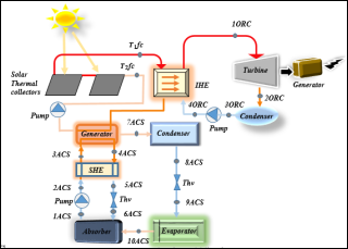
Figure 1. Simplified diagram of the combined ORC and ACS system.
2.2. Energy Analysis
Thermodynamic modeling of the combined cycle ORC/ACS is based on the first law of thermodynamics and the conservation of energy balances and mass. The conservation of mass is in the form:
mi=me (1)
2.2.1. Solar Thermal Field
The energy balance gives the quantity of useful heat recovered by the heat transfer fluid during its passage through the solar collector, which is the sum of the energy released in the evaporator of the organic Rankine cycle and the energy transferred into the generator of the absorption cooling system.
Q̇fc=AcηcG (2)
Q̇fc=ṁfcCpfcT2fc-T1fc=Q̇EC_ORC+Q̇AbACS (3)
Q̇fc=ṁfcCpfcT2fc-T1fc=ṁORCh1ORC-h4ORC+ṁpACS×qAbACS (4)
T2fc and T1fc are respectively the temperature at the outlet and inlet of the solar collector;
2.2.2. ORC Subsystem
Three main assumptions are taken into account:
1) The system reaches a steady state;
2) Pressure losses in the pipes;
3) Heat losses in ORC components are neglected.
The inlet and outlet mass flow rates are equal in steady state. The relationships between the flow rates are given by the equation below:
ṁ1ORC=ṁ2ORC=ṁ3ORC=ṁ4ORC (5)
The equations used to perform the energy analysis at the ORC subsystem level are as follows:
At the level of the Intermediate heat exchanger (IHE):
Q̇EC_ORC=ṁORCh1ORC-h4ORC (6)
At the turbine level:
ẆT_ORC=ṁORCh2ORC-h1ORC (7)
At the condenser level:
Q̇Cd_ORC=ṁORCh3ORC-h2ORC(8)
At the pump level:
ẆP_ORC=ṁORCh4ORC-h3ORC (9)
Thus the thermal efficiency of the ORC is given by:
ηORC=ẆTORC-ẆP_ORCQ̇EC_ORC (10)
2.2.3. ACS Subsystem
The mass balance of the H2O/LiBr solution is written as shown in equation 11.
ṁr_ACS=ṁp_ACS+ṁref_ACS (11)
The mass flow rate of the chilled water in the evaporator is given by equation 12.
ṁwACS=Q̇Ev_ACScp(TEviACS-TEveACS) (12)
The equations which describe the energy balances, mass balance and coefficient of performance for the different components of the ACS subsystem are presented below:
Evaporator:
qEv_ACS=h10-h9 (13)
ṁef_ACS=Q̇Ev_ACSq̇Ev_ACS (14)
Condenser
qcd_ACS=h7-h8(15)
Q̇Cd_ACS= ṁref_ACS×qCd_ACS (16)
Generator
Q̇G_ACS=ṁref_ACSh7-h4+ṁp_ACSh4-h3 (17)
qG_ACS=Q̇G_ACSṁr_ACS (18)
ṁr_ACS=ṁp_ACS+ṁref_ACS (19)
Absorber
qAb_ACS=(h10-h6)+f(h6-h1)(20)
Q̇Ab_ACS= ṁp_ACS×qAb_ACS(21)
The solution flow ratio (f) is defined by the ratio of the mass flow rate of the pore solution in refrigerant and the mass flow rate of the refrigerant. This ratio should be noted because it represents the pumping energy required.
The coefficient of performance (COP) represents the measurement of the performance of a cooling machine and is defined as follows:
COPACS=Q̇Ev_ACSQ̇G_ACS+ẆP_ACS (22)
3. Results and Discussions
After carrying out the energy analysis of each subsystem, the results of each component using the EES software will be detailed and discussed.
3.1. ACS Subsystem
Figure 2 gives the circulation rate as a function of the absorption temperature. The circulation rate represents the ratio of the total mass flow rate of the weak absorbent solution entering in the generator compared to the mass flow rate of refrigerant vapor leaving the generator. It gives an indication of the size of the ACS per unit of heat production. The general objective for the ACS system is to minimize its value.
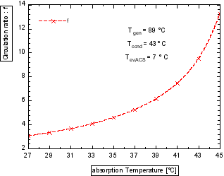
Figure 2. Evolution of the circulation factor as a function of the absorption temperature.
Figure 2 shows that for fixed generator, condenser and evaporator temperatures at 89°C, 43°C and 7°C respectively, the circulation factor increases with the absorption temperature. Thus, when the temperature of the heat source is high then the circulation rate of the working fluid increases with the increase in the absorption temperature.
The enthalpies at the evaporator, condenser, generator and absorber are given in Figure 3 for generator temperature of 90°C, condenser temperature of 43°C and evaporator temperature of 7°C.
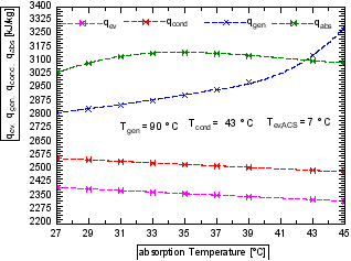
Figure 3. Evolution of enthalpies at the evaporator, condenser, generator and absorber as a function of absorption temperature.
Figure 3 shows that the enthalpy at the evaporator and at the condenser decreases when the absorption temperature increases. However, one notes a linear increase in enthalpy at the generator level. The enthalpy at the absorber increases slightly with the increase of the absorption temperature until reaching a maximum value corresponding to an absorption temperature of 33°C then decreases considerably.
Absorption cooling system COP for fixed temperatures of absorber, condenser and evaporator is given by Figure 4.
Figure 4. Absorption cooling system COP for fixed temperatures of absorber, condenser and evaporator as a function generator temperature.
The variation of COP as a function of generator temperature is not inversely proportional to the variation of circulation rate, but rather depends on the variation of generator temperature. As the generator temperature increases, the heat per unit mass of solution required to separate the refrigerant from the absorbent-poor solution increases since the difference in absorbent concentration between the generator and the absorber increases. On the other hand, the circulation rate decreases and leads to a reduction in the flow of lean solution to be heated in the generator. The variation of the COP depends on the dominant character, either the need for heat necessary for separation, or the necessary flow rate of solution to be heated. Depending on the values of the evaporator temperature and the condenser (and absorber) temperature, it is possible to define which of the two has a dominant character. The influence of rising condenser temperature on the COP at the low temperature of the generator is more eminent than when the generator temperature is increased. If the condenser temperature is fixed at 42°C, the chiller can not operate at generator temperature below 88°C. So, COP values before generator temperature achieves 88°C can not be obtained in practice as condensation temperature is fixed at 42°C.
Figure 5 gives the evolution of the COP ACS as a function of the absorption temperature, for temperatures of generator, absorber and evaporator fixed respectively at 90°C, 42°C and 7°C.
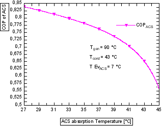
Figure 5. Evolution of ACS efficiency as a function of ACS absorption temperature.
Figure 6 shows that the COP ACS decreases when the absorption temperature increases. This reduction goes from 0.83 to 0.55, i.e. a reduction of 0.28 for a variation of absorption temperature from 27°C to 45°C. So for better performance, the absorber must be cooled.
Figure 6 gives the COP ASC as a function of the temperature of condensation, for temperatures fixed at the generator, absorber and evaporator to 90°C, 42°C and 7°C respectively.
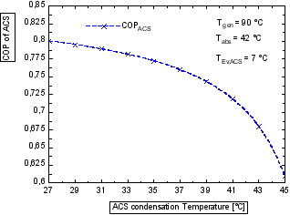
Figure 6. Evolution of ACS efficiency as a function of ACS condensing temperature.
Figure 6 shows that the COP ACS decreases when the temperature of condensation increases. The COP ACS decreases from 0.8 to 0.6 when the temperature of condensation increases from 27°C to 45°C. Like absorption, for better efficiency the condenser must be cooled.
From the values in Figure 5 and Figure 6, the COP decreases with the increase of absorber and condenser temperature. As explained before, for a constant generator temperature, the generator power decreases as the circulation rate decreases and vice versa. For a constant evaporation temperature where the evaporator power is constant, the COP decreases.
Figure 7 gives the ACS COP as a function of the temperature of evaporation for a generator temperature equal to 90°C and a temperature of 42°C at the absorber which is equal to that of the condenser.
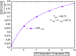
Figure 7. Evolution of ACS efficiency as a function of ACS evaporation temperature.
Figure 7 shows that the COP ACS increases with the increase of evaporation temperature. This variation is explained by equilibrium between the latent heat available in the evaporator and the thermal power required in the generator to separate a quantity of refrigerant. Considering a fixed refrigerant flow rate, the increase of evaporator temperature causes the latent heat of vaporization to decrease because the saturation pressure of the evaporator increases. At the same time, the decrease of circulation rate with the increase of evaporation temperature involves the decrease of the flow rate of the poor absorbent solution circulating from the absorber to the generator. Therefore, the power required to separate the solution in the generator decreases. This reduction is greater than the reduction in the power of the evaporator, which leads to an increase of the COP.
3.2. ORC Subsystem
Figure 8 gives the turbine power, the pump power, the evaporator power and the ORC efficiency for an ORC system evaporation temperature equal to 147°C and a mass flow rate of 1.25 kg/s.
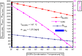
Figure 8. Evolution of the turbine power, the pump power, the evaporator power and the ORC efficiency as a function of the ORC condensation temperature.
Figure 8 shows that the ORC efficiency increases strongly when the ORC condensation temperature decreases. It also shows that the turbine power and the amount of heat at the ORC evaporator decrease with the increase of the condensation temperature of the ORC system. The pump power is almost constant with the increase of the ORC condensation temperature up to a value of 60°C before starting to decrease.
Figure 9 gives the ORC efficiency as a function of mass flow.
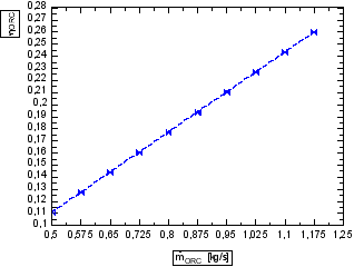
Figure 9. Evolution of ORC efficiency as a function of ORC mass flow rate.
Figure 9 shows that the ORC efficiency increases linearly with increasing mass flow rate. The efficiency starts to increase from a mass flow rate of 0.5 kg/s.
Figure 10 gives the evolution of the turbine power and the condenser power of ORC as a function of the ORC condensation pressure.
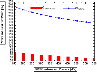
Figure 10. Evolution of the turbine power and the condenser power of the ORC as a function of the condensation pressure of the ORC.
Figure 10 shows that the turbine power and the ORC condenser power decrease when the ORC condensation pressure increases. Thus, the turbine power increases from 235 kW to 200 kW and the ORC condenser power increases from 80 kW to 60 kW.
Figure 11 gives the effect of the temperature of the heat source on the efficiency of ORC and ACS system.
In Figure 11 one notes that for an increase in the temperature of the heat source, the energy efficiency of the organic Rankine cycle increases slightly. This is normal because the optimal heat source temperature for an ORC with R245fa as working fluid is 170°C. Likewise, Figure 11 shows a decrease in COPACS. This is because, for a single-effect solar absorption cooling system in hot regions, the system of performance takes its optimum value at heat source temperatures between 75 and 80°C.
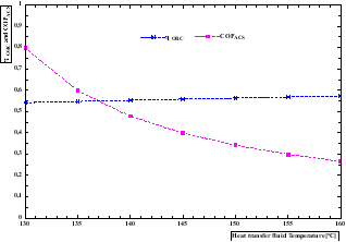
Figure 11. Effect of heat source temperature on ORC efficiency and ACS COP.
4. Conclusion
The aim of this study is to carry out a thermodynamic analysis of a combined system ORC and ACS for power electricity and cooling.
For this purpose, a simulation model was solved using the EES software, in order to study the performance of the system. The simulation results allow us to draw the following conclusions:
1. Power delivered by the turbine decreases when the condensation pressure increases
2. ORC efficiency improves when the mass flow rate of the working fluid increases
3. Absorption temperature has a great influence on the heat exchanges of the different components of the ACS
4. Higher COP values are obtained for high evaporation temperatures
5. Temperature of the heat source has a very large influence on the performance of the combined ORC-ACS system.
The ORC-ACS combined system is one of the most promising sustainable technologies, and it has a great advantage in hot regions due to the availability of a large solar field and due to the quasi-synchronization of the cooling load of peaks with available solar energy. However, the availability of drinking water is a major problem in rural areas. So, we are thinking about water desalination, therefore an ORC, ACS and water desalination combined system.
Abbrevation

A 

Area [m2]

ACS

Absorption Cooling System [-]

COP

Coefficient of Performance [-]

Cp 

Mass Heat [kj/kg. K]

G

Irradiation [W/m2]

h 

Enthalpy [kJ/kg]

m

Mass [kg]

ṁ 

Mass Flow [kg/s]

η 

Efficiency [-]

ORC

Organic Rankine Cycle [-]

q 

Mass Work [kJ/kg]

Q̇

Power [kW]

T 

Temperature [°C]

Ẇ

Power [kW]

a 

Ambient

c 

Collector

cd 

Condenser

e 

Inlet

Ec 

Exchanger

Ev 

Evaporator

f 

Fluid

fc 

Working Fluid

G 

Generator

i 

Outlet

m 

Average

Author Contributions
Serigne Thiao: Conceptualization, Funding acquisition, Investigation, Methodology, Project administration, Resources, Validation, Writing – original draft
Mamadou Sow: Data curation, Funding acquisition, Investigation, Resources, Software
Sokhna Khady Fall: Funding acquisition, Investigation, Resources, Software
Awa Mar: Funding acquisition, Investigation, Project administration, Resources
Diouma Kobor: Methodology, Resources, Supervision, Validation
Issakha Youm: Formal Analysis, Resources, Supervision, Validation
Acknowledgments
This work was supported by the laboratory of chemistry and physics of materials of the Assanse Seck University of Ziguinchor, Senegal.
Conflicts of Interest
The authors declare no conflicts of interest.
References
[1] G. Bamorovat Abadi and K. C. Kim, ‘Investigation of organic Rankine cycles with zeotropic mixtures as a working fluid: Advantages and issues’, Renewable and Sustainable Energy Reviews, vol. 73, pp. 1000–1013, Jun. 2017,
[2] E. Barbier, ‘Geothermal energy technology and current status: an overview’, Renewable and Sustainable Energy Reviews, vol. 6, no. 1, pp. 3–65, Jan. 2002,
[3] M. Hamlehdar et al., Hydrogen production from low-temperature geothermal energy – A review of opportunities, challenges, and mitigating solutions. International Journal of Hydrogen Energy 77 (2024) pp: 742–768,
[4] H. Wenge, W. Jiangfeng, L. Zhijian, W. Sheng, Exergoeconomic and exergoenvironmental analysis of a combined heating and power system driven by geothermal source, Energy Convers. Manag. vol. 211, May 2020, pp: 112765.
[5] Murat Ozturk, Ibrahim Dincer, A new geothermally driven combined plant with energy storage option for six useful outputs in a sustainable community, Sustain. Energy Technol. Assess. 45 (2021), pp: 101180, ISSN 2213-1388.
[6] D. Li et al.; Resource endowments effects on thermal-economic efficiency of ORC-based hybrid solar-geothermal system. Case Studies in Thermal Engineering vol. 52, 2023, pp: 103739.
[7] G. Fan et al, Energy and exergy and economic (3E) analysis of a two-stage organic Rankine cycle for single flash geothermal power plant exhaust exergy recovery, Case Studies in Thermal Engineering vol. 28 2021, pp: 101554.
[8] E. Assareh et al., A newly application of Organic Rankine Cycle for building energy management with cooling heating power hydrogen liquefaction generationSouth Korea. Energy Nexus vol. 13, 2024, pp: 100281.
[9] S. Quoilin, M. Orosz, H. Hemond, and V. Lemort, ‘Performance and design optimization of a low-cost solar organic Rankine cycle for remote power generation’, Solar Energy, vol. 85, no. 5, pp. 955–966, May 2011,
[10] T. Z. Kaczmarczyk, Experimental research of a small biomass organic Rankine cycle plant with multiple scroll expanders intended for domestic use, Energy Convers. Manag. vol. 2442021, pp: 114437,
[11] L. S. Budovich. Energy, exergy analysis in a hybrid power and hydrogen production system using biomass and organic Rankine cycle, International Journal of Thermofluids vol. 21, 2024, pp: 100584.
[12] Joaquín Navarro-Esbrí et al., Combined cold, heat and power system, based on an organic Rankine cycle, using biomass as renewable heat source for energy saving and emissions reduction in a supermarket. Energy Procedia vol. 129, 2017, pp: 652–659.
[13] A. Alghamdi et al., Exergy-economic analysis of a hybrid combined supercritical Brayton cycle-organic Rankine cycle using biogas and solar PTC system as energy sources. Case Studies in Thermal Engineering vol. 50, 2023, pp: 103484.
[14] D. A. Baharoon, H. A. Rahman, W. Z. W. Omar, and S. O. Fadhl, ‘Historical development of concentrating solar power technologies to generate clean electricity efficiently – A review’, Renewable and Sustainable Energy Reviews, vol. 41, pp. 996–1027, Jan. 2015,
[15] M. H. Farhat et al., Energy optimization of parabolic dish solar concentrator coupled to organic Rankine cycle: Experimental and analytical investigation of cavity receiver design and covering effects. International Journal of Thermofluids, vol. 23, 2024, pp: 100730.
[16] Song J, Li X-S, Ren X-D, Gu C-W. Performance analysis and parametric optimization of supercritical carbon dioxide (S-CO2) cycle with bottoming Organic Rankine Cycle (ORC). Energy, vol. 143, 2018; pp: 406–416.
[17] Zhang Q, Wang Z, Du X, Yu G, Wu H. Dynamic simulation of steam generation system in solar tower power plant. Renewable Energy; vol 135, 2019, pp: 866–876.
[18] S. Zhang and Y. Yan. Thermal performance of latent heat energy storage system with/without enhancement under solar fluctuation for Organic Rankine power cycle. Energy Conversion and Management, vol 270, 2022, pp: 116276.
[19] Y. Li et al., 3E analyses of a cogeneration system based on compressed air energy storage system, solar collector and organic Rankine cycle, Case Studies in Thermal Engineering, vol. 42, 2023, pp: 102753.
[20] J. Jawad et al., Pilot testing of water utilization for integrated solar energy storage and power production using linear Fresnel collector and organic Rankine cycle. Energy Conversion and Management: vol. 23, 2024, pp: 100625.
[21] K. Sun, T. Zhao, S. Wu et al.. Comprehensive evaluation of concentrated solar collector and Organic Rankine cycle hybrid energy process with considering the effects of different heat transfer fluids. Energy, vol. 7, 2021, pp: 362–384.
[22] N. Khani et al.; 6E analyses of a new solar energy-driven polygeneration system integrating CO2 capture, organic Rankine cycle, and humidification-dehumidification desalination. Journal of Cleaner Production, vol. 379, 2022, pp: 134478.
[23] Elsaid, K., Taha Sayed, E., Yousef, B. A. A., Kamal Hussien Rabaia, M., Ali Abdelkareem, M., & Olabi, A. G. (2020). Recent progress on the utilization of waste heat for desalination: A review. Energy Conversion and Management, 221, Article 113105.
[24] S. Lecompte, H. Huisseune, M. Van den Broek, B. Vanslambrouck, and M. De Paepe, ‘Review of organic Rankine cycle (ORC) architectures for waste heat recovery’, Renewable and Sustainable Energy Reviews, vol. 47, Jul. 2015, pp. 448–461,
[25] P. Bombarda, C. Invernizzi, and M. Gaia, ‘Performance Analysis of OTEC Plants With Multilevel Organic Rankine Cycle and Solar Hybridization’, J. Eng. Gas Turbines Power, vol. 135, Issue 4: 042302, Apr. 2013, pp: 8,
[26] L. F. Moreira and F. R. P. Arrieta, ‘Thermal and economic assessment of organic Rankine cycles for waste heat recovery in cement plants’, Renewable and Sustainable Energy Reviews, vol. 114, 2019, pp. 109315,
[27] Pili, R., García Martínez, L., Wieland, C., & Spliethoff, H. (2020). Techno-economic potential of waste heat recovery from German energy-intensive industry with Organic Rankine Cycle technology. Renewable and Sustainable Energy Reviews, 134, Article 110324.
[28] Njoku, I. H., Oko, C. O. C., Ofodu, J. C., & Pham, D. (2018). Performance evaluation of a combined cycle power plant integrated with organic Rankine cycle and absorption refrigeration system. Cogent Engineering, 5(1).
[29] S.S. Bishal et al., Performance evaluation of an integrated cooling and power system combining supercritical CO2, gas turbine, absorption refrigeration, and organic rankine cycles for waste energy recuperating system. Results in Engineering, vol. 17, March 2023, 100943.
[30] M.F. Qureshi et al., Thermal analysis of solar energy based organic Rankine cycle cascaded with vapor compression refrigeration cycle. Energy Nexus, vol. 14, july 2024, pp; 100291.
[31] M. A. Mehrabian and A. E. Shahbeik, ‘Thermodynamic modelling of a single-effect LiBr-H2O absorption refrigeration cycle’, Proceedings of the Institution of Mechanical Engineers, Part E: Journal of Process Mechanical Engineering, vol. 219, no. 3, pp. 261–273, Aug. 2005,
[32] K. R. Ullah, R. Saidur, H. W. Ping, R. K. Akikur, and N. H. Shuvo, ‘A review of solar thermal refrigeration and cooling methods’, Renewable and Sustainable Energy Reviews, vol. 24, pp. 499–513, Aug. 2013,
[33] R. Rayegan and Y. X. Tao, ‘A procedure to select working fluids for Solar Organic Rankine Cycles (ORCs)’, Renewable Energy, vol. 36, no. 2, Feb. 2011, pp. 659–670,
[34] S. Khatoon, N. M. A. Almefreji, and M.-H. Kim, ‘Thermodynamic Study of a Combined Power and Refrigeration System for Low-Grade Heat Energy Source’, Energies, vol. 14, no. 2, Art. no. 2, Jan. 2021,
Cite This Article
  • APA Style

    Thiao, S., Sow, M., Fall, S. K., Mar, A., Kobor, D., et al. (2025). Energy Analysis of a Thermodynamic System Combined Organic Rankine Cycle and Absorption Cooling System for Power and Cooling: Effects of Pressure and Temperature. International Journal of Sustainable and Green Energy, 14(1), 42-52. https://doi.org/10.11648/j.ijsge.20251401.14

    Copy | Download

    ACS Style

    Thiao, S.; Sow, M.; Fall, S. K.; Mar, A.; Kobor, D., et al. Energy Analysis of a Thermodynamic System Combined Organic Rankine Cycle and Absorption Cooling System for Power and Cooling: Effects of Pressure and Temperature. Int. J. Sustain. Green Energy 2025, 14(1), 42-52. doi: 10.11648/j.ijsge.20251401.14

    Copy | Download

    AMA Style

    Thiao S, Sow M, Fall SK, Mar A, Kobor D, et al. Energy Analysis of a Thermodynamic System Combined Organic Rankine Cycle and Absorption Cooling System for Power and Cooling: Effects of Pressure and Temperature. Int J Sustain Green Energy. 2025;14(1):42-52. doi: 10.11648/j.ijsge.20251401.14

    Copy | Download

  • @article{10.11648/j.ijsge.20251401.14,
      author = {Serigne Thiao and Mamadou Sow and Sokhna Khady Fall and Awa Mar and Diouma Kobor and Issakha Youm},
      title = {Energy Analysis of a Thermodynamic System Combined Organic Rankine Cycle and Absorption Cooling System for Power and Cooling: Effects of Pressure and Temperature
    },
      journal = {International Journal of Sustainable and Green Energy},
      volume = {14},
      number = {1},
      pages = {42-52},
      doi = {10.11648/j.ijsge.20251401.14},
      url = {https://doi.org/10.11648/j.ijsge.20251401.14},
      eprint = {https://article.sciencepublishinggroup.com/pdf/10.11648.j.ijsge.20251401.14},
      abstract = {In the current economic, energy and environmental context, the implementation of technologies using renewable energies as a source of power electricity and cooling production is very beneficial insofar as it allows the reduction of pollution and the cost of fossil fuels. Senegal has a sunshine potential well distributed across the country for irradiation varying from South to North between 1850 KWh/m²/year and 2250 kWh/m²/year. It is one of the best solar potentials in the world. Systems operating on the organic Rankine cycle ORC and the absorption cooling system ACS are innovative and sustainable technologies for the exploitation of low enthalpy renewable energy sources. In this present work, the thermodynamic analysis of a combined ORC and ACS system for power electricity and cold production is carried out numerically using the Engineering Equation Solver (EES) software. R245fa and water-lithium bromide mixture are used as working fluid for ORC and ACS respectively. The results obtained at the ACS subsystem level show that the COP of ACS decreases when the absorption temperature increases. This reduction goes from 0.83 to 0.55, i.e. a reduction of 0.28 for a variation of absorption temperature from 27°C to 45°C. The COP has stabilized for generator temperatures above 95°C and is in the range of 0.7 to 0.8. These fluctuations are due to the irreversibility at the level of the components of the system. For the ORC subsystem, the turbine power and ORC condenser power decrease as the ORC condensing pressure increases. Thus, the turbine power goes from 235 kW to 200 kW and the ORC condenser power goes from 80 kW to 60 kW.
    },
     year = {2025}
    }
    

    Copy | Download

  • TY  - JOUR
    T1  - Energy Analysis of a Thermodynamic System Combined Organic Rankine Cycle and Absorption Cooling System for Power and Cooling: Effects of Pressure and Temperature
    
    AU  - Serigne Thiao
    AU  - Mamadou Sow
    AU  - Sokhna Khady Fall
    AU  - Awa Mar
    AU  - Diouma Kobor
    AU  - Issakha Youm
    Y1  - 2025/02/20
    PY  - 2025
    N1  - https://doi.org/10.11648/j.ijsge.20251401.14
    DO  - 10.11648/j.ijsge.20251401.14
    T2  - International Journal of Sustainable and Green Energy
    JF  - International Journal of Sustainable and Green Energy
    JO  - International Journal of Sustainable and Green Energy
    SP  - 42
    EP  - 52
    PB  - Science Publishing Group
    SN  - 2575-1549
    UR  - https://doi.org/10.11648/j.ijsge.20251401.14
    AB  - In the current economic, energy and environmental context, the implementation of technologies using renewable energies as a source of power electricity and cooling production is very beneficial insofar as it allows the reduction of pollution and the cost of fossil fuels. Senegal has a sunshine potential well distributed across the country for irradiation varying from South to North between 1850 KWh/m²/year and 2250 kWh/m²/year. It is one of the best solar potentials in the world. Systems operating on the organic Rankine cycle ORC and the absorption cooling system ACS are innovative and sustainable technologies for the exploitation of low enthalpy renewable energy sources. In this present work, the thermodynamic analysis of a combined ORC and ACS system for power electricity and cold production is carried out numerically using the Engineering Equation Solver (EES) software. R245fa and water-lithium bromide mixture are used as working fluid for ORC and ACS respectively. The results obtained at the ACS subsystem level show that the COP of ACS decreases when the absorption temperature increases. This reduction goes from 0.83 to 0.55, i.e. a reduction of 0.28 for a variation of absorption temperature from 27°C to 45°C. The COP has stabilized for generator temperatures above 95°C and is in the range of 0.7 to 0.8. These fluctuations are due to the irreversibility at the level of the components of the system. For the ORC subsystem, the turbine power and ORC condenser power decrease as the ORC condensing pressure increases. Thus, the turbine power goes from 235 kW to 200 kW and the ORC condenser power goes from 80 kW to 60 kW.
    
    VL  - 14
    IS  - 1
    ER  - 

    Copy | Download

Author Information