Research Article | | Peer-Reviewed

Building Structural Design Innovation and Code Development

Received: 21 February 2024    Accepted: 14 March 2024    Published: 2 April 2024
Views:       Downloads:
Abstract

In recent years, Some new structural systems and design difficulties of high-rise and super high-rise buildings were emerged in Shenzhen, such as forced displacement and non-forced displacement, story lateral stiffness calculation method, frame-core wall structures with partial perimeter frame beams missing, super high-rise structure with great height-width ratio, high-rise less shear walls in one direction structure, conjoined tower structures, high-rise structure with inclined column, mega structure with belt truss, rare earthquake design method etc. The emergence and solution of these problems reflect the innovation of the structural design of high-rise buildings. Meanwhile, Structural design has encountered many difficulties and new problems. The solutions to these problems sometimes conflict with the current Chinese code, or there are no relevant provisions in the Chinese code. The current Chinese code is the basis for designing of high-rise buildings, which is the crystallization of the wisdom of previous generations, but the emergence of various new types of building structures has brought about numerous difficulties in structural design. Therefore, during the design process, it is necessary to conduct research, innovation, supplementation, and development of the current code. In view of this situation, this paper combines the previous engineering practical experience and introduces some structural design points of complex super high-rise buildings located in Shenzhen. It is for designers' reference, which also provides content for the revision of the specification.

Published in International Journal of Architecture, Arts and Applications (Volume 10, Issue 1)
DOI 10.11648/j.ijaaa.20241001.12
Page(s) 9-19
Creative Commons

This is an Open Access article, distributed under the terms of the Creative Commons Attribution 4.0 International License (http://creativecommons.org/licenses/by/4.0/), which permits unrestricted use, distribution and reproduction in any medium or format, provided the original work is properly cited.

Copyright

Copyright © The Author(s), 2024. Published by Science Publishing Group

Keywords

High-Rise Building, Structural Design, Inter-Story Drift Ratio, Story Lateral Stiffness, Great Height-Width Ratio

1. Introduction
In recent years, various high-rise and super high-rise buildings have emerged in Shenzhen. Structural design has encountered many difficulties and new problems. The solutions to these problems sometimes conflict with the current code, or there are no relevant provisions in the code. Therefore, during the design process, it is necessary to conduct research, innovation, supplementation, and development of the current code.
2. High-Rise Building Structural Forced and Non-Forced Displacement
The inter-story displacement of the building structure consists of two parts: forced displacement and non-forced displacement. The rigid displacement generated at the upper part of the structure due to the rotation of the bottom of the vertical wall or column constitutes the non-forced displacement.
The maximum inter-story displacement of high-rise buildings generally occurs in the upper part of the structure. At this time, the non-forced inter-story displacement accounts for a large proportion and the forced inter-story displacement accounts for a small proportion; at the embedded floor of the structure bottom, the inter-story displacement of the first floor is its forced displacement, and the non-forced inter-story displacement is zero. The inter-story drift ratio limit value in “Technical Specification for Concrete Structures of Tall Building” (JGJ 3-2002) (referred to as old version JGJ) and “Technical Specification for Concrete Structures of Tall Building” (JGJ 3-2010) (referred to as current JGJ) is 1/500, which is very small. However, the basic wind pressure with a 50-year return period in Shenzhen area is 0.75kN/m2, which is relatively large, so the calculated value of inter-story drift ratio of the structure often does not meet the requirements of the code.
Shenzhen Di Wang Tower (Figure 1) has a height of 368m, 69 floors above ground, and an aspect ratio of 8.8. The first two periods of the structure are 6.19s (X) and 5.69s (Y). The drift ratio under the basic wind pressure with a 100-year return period in the X direction of the top of the structure is 1/373, and the maximum inter-story drift ratio is 1/274 (57th floor). Analysis shows that the inter-story drift ratio is composed of two parts: forced inter-story drift ratio and non-forced inter-story drift ratio. The forced inter-story drift ratio of the shear wall on the 57th floor where the maximum inter-story drift ratio of this structure is located is only 1/28195, which is less than 1% of the inter-story drift ratio.
Figure 1. Shenzhen Di Wang Tower.
Shenzhen KINGJEE 100 (Figure 2) is adjacent to Di Wang Tower with a three-story basement and 100 floors above ground. The building height is 441.8m, and the average height-width ratio reaches 10.2. The maximum inter-story drift ratio under the wind load with a return period of 50 years exceeds the code limit of 1/500. Upon analysis, the inter-story drift ratio of shear walls and frame columns at the floor with the maximum inter-story displacement is only 0.7%~1.8% of inter-story drift ratios. From these engineering practices, we can draw the following conclusions: even if there are large inter-story drift ratios under wind action, there are no safety issues with structures.
The wind tunnel test results of the Di Wang Tower conducted by the University of Western Ontario in Canada show that under the wind load with a return period of 10 years, the maximum lateral acceleration at the top is: X direction: 23.5cm/s2, Y direction: 11.0cm/s2, radial direction (torsion): 13.9cm/s2. After the construction of Shenzhen KINGJEE 100 was completed, the instantaneous peak acceleration at maximum wind speed measured for 5 consecutive years was 12.3cm/s2. The wind-induced acceleration of the above two projects both meet the human comfort criteria of 25cm/s2 and 15cm/s2.
The above cases show that old version JGJ and current JGJ’s provisions on limit values of inter-story drift ratios under wind action seem to be too strict and should be appropriately relaxed.
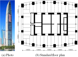
Figure 2. Shenzhen KINGJEE 100.
3. The Calculation of Lateral Stiffness for High-Rise Buildings with Large Floor Heights at Lower Stories
The calculation formulas for the lateral stiffness in the old version JGJ, current JGJ and the supplementary provisions of Guangdong Province local code “Technical Specification for Concrete Structures of Tall Building” (D BJ/T5-46-2005), (referred to as the 2005 version D BJ/T5) are different. The discussion is as follows.
The definition of lateral stiffness in old version JGJ is as follows:
Ki=Vi/i(1)
inter-story lateral stiffness ratio:
KiKi+1=ViVi+1i+1i(2)
where
Ki,Ki+1= lateral stiffness of i, i+1 story respectively
Vi, Vi+1= story shear forces of i, i+1 story respectively
i, i+1= lateral displacement of i, i+1 story respectively
The approximate inter-story lateral stiffness ratio of the middle and lower stories is KiKi+1i+1i, and the inter-story lateral stiffness ratio of the bottom is K1K221, When the height of the bottom story is very large, the ratio of lateral stiffness is obviously smaller.
Assume that the lateral stiffness is:
Ki=Vi/θi=Vihi/i(3)
where
θi= drift ratio of the i story
hi= height of the i story
The approximate inter-story lateral stiffness ratio of the middle and lower stories is KiKi+1=ViVi+1i+1ihihi+1i+1ihihi+1=θi+1θi, and the inter-story lateral stiffness ratio of the bottom is K1K2θ2θ1.
Formula (3) is consistent with the formula of the lateral stiffness in the 2005 version D BJ/T5. When the floor height of the bottomis very large, the lateral stiffness of the bottom is obviously exaggerated, and the height of the bottom story increases, and the lateral stiffness increases.
From the above discussion, it can be seen that the conclusion of the old version JGJ and 2005 version D BJ/T5 is inconsistent, which confuses users. Current JGJ and Guangdong Province's "Technical Specification for Concrete Structures of Tall Building " (DBJ 15-92-2013) (referred to as the 2013 version D BJ/T5) adopts the same formula as the 2005 version D BJ/T5, but the provisions of the bottom embedded floor. The ratio of the lateral stiffness of the first floor to that of the floor above it should not be less than 1.5, which is a correction of the 2005 version D BJ/T.
Qian Hai financial center T1 tower has a height of 249.03m, 54 floors, the curtain wall above the roof is 11.7m. 2 mega columns on each side of the standard floor plane, a total of 8 mega columns. The mega composite columns are splayed along the vertical direction. The column-span is reduced from 26.6m at the bottom layer to about 22.6m at the top, and the perimeter frame beam span is large. The standard story height is 4.50m, the first story height is 19.50m, and 8th, 19th, 30th, 41st are 5.10m. Figure 3 shows the standard plane of the building and the Main lateral resistance components. The results of the lateral stiffness of Figure 4 are calculated by the old version JGJ, the 2013 version D BJ/T5 and the literature , respectively.
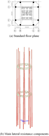
Figure 3. Qian Hai financial center T1 tower.
Figure 4. Lateral stiffness comparison.
It can be seen from Figure 4:
1) the lateral stiffness of high-rise building structure except for the bottom floor (the bottom is the embedded floor) shows the trend of "small on top and big on the bottom";
2) the lateral stiffness of the 19th and 41st floors which are equipped with belt trusses and outrigger trusses obviously increases, and this phenomenon can be obviously reflected in the lateral stiffnesses calculated by the literature, while the the old version JGJ do not obviously reflect this phenomenon. Furthermore, the results calculated by the 2013 version D BJ/T5 is smaller than the literature.
3) For the 8th and 30th stories with the story height of 5.10m, the height of these two stories becomes larger, which results in the reduction of the lateral stiffness. Only the literature can obviously reflect this phenomenon.
4) For the first story with a height of 19.50m, the lateral stiffness calculated by the old version JGJ and the method of the literatureis relatively small, while the lateral stiffness calculated by the 2013 version D BJ/T5 is much larger, which is obviously not reasonable. It is obvious that the calculation method of lateral stiffness in the current JGJ and the 2013 version D BJ/T5 needs further research and improvement.
4. The Engineering Cases of Complex Super High-Rise Buildings

4.1. Frame–Core Wall Structure with Partial Perimeter Frame Beam Missing

Article 9.2.3 of the current JGJ stipulates that perimeter frame beams must be provided between perimeter frame columns of frame–core wall structure.
The tower of Shenzhen New World Center has 53 floors above ground, with a building height of 219m, adopting a frame-core structure system, and the structural layout of the podium is shown in Figure 5. Due to the architect's high requirements on building space and aesthetics, there is a 31.5m-high cross-story corner column at the entrance of the building in the southeastern corner of the plan. This design is not in line with the current JGJ on the frame–core wall structure, which require that perimeter frame beams must be set between perimeter frame columns, and adequate demonstration of safety must be carried out during design.
Figure 5. Podium of the Shenzhen New World Center.
The essence of the problem of the frame–core wall structure with partial perimeter frame beams missing is that:
1) The missing perimeter frame beams causes a reduction in the lateral stiffness of the frame.
2) Redistribution of core wall and frame shear forces.
3) Redistribution of lateral forces in frame columns.
4) When a perimeter frame beam is missing at only one side, a certain amount of torsion of the structure will be occurred.
5) The stability of the cross-story column without perimeter frame beams at both ends should meet the code criteria (including rare-earthquake).
It seems that all of the above problems are not technically difficult to solve, and when the design is well justified and appropriate reinforcement measures are taken, it should be feasible for the frame–core wall structure to have missing perimeter frame beams.

4.2. Inclined Column

The bottom end of the inclined column produces a large concentrated tension force on the diaphram. The turning point of the inclined column generates a large concentrated tension on the diaphram, and affects the force on the upper and lower floors. The relevant structural design method lacks the provisions and contents in this regard in the current JGJ. When designing, it is necessary to control the main tensile stress of the concrete of the diaphram under gravity load, wind load and frequent earthquake action not to exceed the characteristic value of material strength. The measures to solve the large tensile stress of the diaphram under vertical load include resisting, releasing or resistance-release combination, etc.
The Shenzhen OCT Tower has 59 floors above ground, with a structural height of 277.4m, and the total height is about 300m high, which adopts the structural form of "mega column frame-core wall with diagonal bracing".
Due to the architectural requirements, the building plane is irregular hexagonal, the core is located in the middle of the plane, also irregular hexagonal. 6 mega columns are arranged in the corners of the plane, 4 mega columns on the east and west sides are tilted with the edges of the building, and the mega columns on the north and south sides are vertical from the bottom to the top. The east side of the building facade slopes outward by about 13° from the ground floor to the 30th floor, while it slopes inward by about 13° from the 30th floor to the top floor. The west side is similar to the east side and slopes approximately 8°, see Figure 6. The building has mega columns inclined and turned, irregular plan, large differences in lateral stiffness in both horizontal directions, and complex force transfer between different types of members in the column frame.
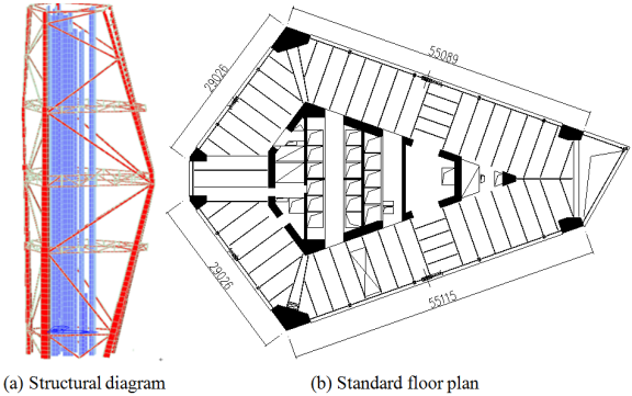
Figure 6. The Shenzhen OCT Tower.
Two mega columns on the east side of the plane are merged into one on the 28th floor, and separated into two on the 31st floor, the mega columns form a large prominent turn, so that under the action of the vertical load on these floors, a large concreted lateral tensile force is generated, and the structure has a certain lateral deformation. Figure 7 shows the tensile stress distribution of the 28th floor slab under characteristic combination of vertical load.
Figure 7. Distribution of tensile stresses in in floor slabs under characteristic combination of vertical loads on the 28th floor/(N/mm2).
For high-rise structures with inclined columns, the new design content of diaphrams can obviously fill in the deficiencies of the design provisions in the current JGJ.

4.3. Super High-Rise Structures with Extremely Large Height-Width Ratio

4.3.1. Relevant Provisions of the Current JGJ

Article 3.3.2 of the current JGJ stipulates the maximum height-width ratio applicable to reinforced concrete high-rise structures, shown in Table 1.
Table 1. The maximum height-width ratio applicable to reinforced concrete high-rise structures.

Structural system

Non-seismic design

Seismic design Basic seismic intensity

Zone 6, 7

Zone 8

Zone 9

Frame structure

5

4

3

Slab-column shearwall structure

6

5

4

Frame-shearwall structure, shear wall structure

7

6

5

4

Frame–core wall structure

8

7

6

4

Tube-in-tube structure

8

8

7

5

Article 11.1.3 of the current JGJ specifies the maximum height-width ratio applicable to mixed structure high-rise buildings, as shown in Table 2.
Table 2. The maximum height-width ratio applicable to mixed structure high-rise structures.

Structural system

Non-seismic design

Seismic design Basic seismic intensity

Zone 6, 7

Zone 8

Zone 9

Frame–core wall structure

8

7

6

4

Tube-in-tube structure

8

8

7

5

Artcle 9.2.1 of the current JGJ stipulates that "the width of the core should not be less than 1/12 of the total height of the core". There are some super slender high-rise structures with a height-width ratio of more than 15 in the United States, such as Central Park Tower in New York, 98 floors above the ground, 472m in hight, with a height-width ratio of about 15. 220 Central Park South in New York, 65 floors above the ground, 290m in hight, with a height-width ratio of about 18. The most slender high-rise structure in Shenzhen is 250m high, with a height-width ratio of 11, and the core wall has a height-width ratio of 35, far exceeding the criteria of the current JGJ.
The structural height-width ratio is mainly determined by the structural rigidity. The measures to realize the super slender high-rise structure are:
1) Control the non-forced displacement of the structure so that it does not affect the structural load capacity.
2) The maximum inter-story displacement limit of the structure under wind load should be appropriately relaxed.
3) Adopt viscous dampers or damping devices such as TMD (tuned mass damper) and TLD (tuned liquid damper) to meet the structural wind-induced vibration acceleration limit.

4.3.2. The Engineering Case

The building heights of the two towers B and C of Shenzhen Hengyu Houhai Center are close to 250m, the height-width ratio is close to 11, and the height-width ratio of the core wall reaches 35. After a large number of analysis and research, the design breaks the inter-storey drift ratio limit of the current JGJ, and viscous dampers are set up in the refuge floors to improve the wind-induced building vibration comfort . It solves the problem of restricted building site and maximizes the satisfaction of building functions, structural safety and comfort.
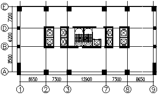
Figure 8. Standard floor plane of Shenzhen Hengyu Houhai Center B and C towers.
Figure 8 shows the building plan of the standard floor. The main structure has been completed, and the structural damping ratio measurement before and after the installation of dampers is being arranged. Regarding the content of dampers for wind-induced vibration reduction, the current JGJ needs to be supplemented and improved.

4.4. The High-Rise Shear Wall Structure with Less Walls in One Direction

The functional requirements of the building call for a floor plan with as few walls as possible in one direction, to allow for better lighting, ventilation, and views. There is a structural form which is not included in the current JGJ, namely the high-rise shear wall structure with less walls in one direction. For this new structural form, the designers have many questions about its force transmission path. Obviously, the structural system in the direction of fewer walls is no longer a shear wall structure.
When the beams in the direction of less walls and the shear walls can form a frame system, it can be treated as a frame-shear wall structure. In the direction of less wall, Shear wall’s out-of-plane shear capacity, bending capacity can not be regarded as the main lateral force resistant, and the current software do not have the function of calculating the wall out-plan capacity.
Huarun Yinhu lanshan residential compound has 44 floors above the ground (the top two floors are for decorative purposes), with a building height of 144.3m and a structural height-width ratio of 7.1. The structural plan of the standard floor is shown in Figure 9.
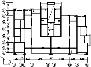
Figure 9. Standard floor plane of Huarun Yinhu lanshan residential compound.
For The high-rise shear wall structure with less walls in one direction, the design should follow the following design concepts:
1) The direction of the less wall (X-direction in Figure 9) should be as much as possible to set up shear walls.
2) The direction of the non-less wall (Y-direction in Figure 9) should be limited to set up shear walls without flanges, columns or flanges should be provided at the end of the shear wall.
3) Control the out-of-plane force of shear walls in Y-direction to reduce the shear force borne by the flat columns-floor frames.
The composition and structural system of the high-rise shear wall structure with less walls in one direction is judged as follows: the less wall direction structure consists of in-plane shear walls, beam-columns frame, flat columns-floor frames, which together resist the lateral load:
1) There are only a small number of in-plane shear walls in the X-direction, which contributes to the formation of “less walls in the X-direction”.
2) The beam-columns frame is a frame consisting of X-oriented beams and columns (including shear wall end columns).
3) In the direction of the less wall (X-direction), Y-directional walls can be regarded as flat columns in X-direction. Hence, the flat column-floor frame consisting of Y-directional walls and floor slabs. Basically it is a frame-shear wall structure.
The high-rise shear wall structure with less walls in one direction is divided into two kinds of frame-shear wall structure system, and the method of controlling the shear force ratio of flat column-floor frame is as follows:
1) When the base shear ratio of flat column-floor slab frame is less than 10%, it should be designed according to the frame-shear wall structure, and the shear wall and beam-column frame bear all the lateral seismic effects;
2) When the base shear ratio of the flat column-floor frame is not less than 10%, in addition to the design of the frame-shear wall structure to bear all the seismic effects in accordance with the current JGJ, the seismic bearing capacity of the flat column-floor frame should also be calculated, and appropriately increase vertical bar reinforcement in the shear wall.

4.5. High-Rise Conjoined Tower Structure

4.5.1. Relevant Provisions of the Current JGJ

Article 10.5.1 of the current JGJ stipulates: "The independent towers of the conjoined tower structures shall have the same or similar body shape, plan layout and stiffness. It is appropriate to adopt biaxial symmetrical plan. In seismic zone 7 and zone 8, if there is a obvious difference in the number of floors and stiffness between multiple towers. It is not suitable to adopt conjoined tower structure." Article 10.5.4 stipulates: "Rigid connection should be adopted between towers of conjoined structure. When rigidly connected, main structural members of the linkbridge should be extended into the tower for at least one span and reliably connected." The above provisions obviously do not meet the needs of the current development of high-rise conjoined tower structure in Shenzhen.

4.5.2. Type of High-Rise Conjoined Tower Structural Forms

1) The height and stiffness of each tower varies significantly.
2) The towers are diagonally connected.
3) Development from twin towers to three or more towers.
4) The tower extends a long cantilever to support the linkbridge.
5) The tower and the linkbridge are connected by a rigid connection, a flexible connection, or a combination of both: a rigid connection means that the tower and the linkbridge are connected without relative displacement; a flexible connection means that the connection can be relatively displaced.

4.5.3. Design Methodology

1) In a conjoined tower structure, each individual tower should be able to stand alone, and its structural indicators, including the load capacity of the components, should all meet the requirements of the code.
2) The linkbridge should adopt a steel structure.
3) Main load-bearing members of rigid connection end of the linkbridge should extend into the tower for 1~2 spans. When the linkbridge is diagonal connection, the part extending into the tower should form a horizontal truss, which transmits the lateral force to the core or other reliable member.
4) When cantilever truss supports the linkbridge, the end of truss should reach into the tower reliably to control the deformation and vibration comfort of cantilever end.
5) At the rigid connection between tower and linkbridge, beams, columns, shear walls and other members in the tower should be reinforced appropriately.
6) When linkbridges between multiple towers are connected by rigidity, they will cause the towers to constrain each other, which may result in a surge of internal force in a tower. In this case, structural members should meet the seismic performance objectives. To a certain extent, the tower with high rigidity can play a role in helping to support the tower with weak rigidity.
7) Flexible connection can release the shear force at the connection, so that the tower can be relatively independent. The displacement and reset capacity of the connection should be controlled during design.
8) According to different building functions, structural characteristics, it is also feasible to use both rigid and flexible connections in conjunction with each other.

4.5.4. The Engineering Case

Shenzhen Gemdale Viseen Tower has two towers, A and B. The building height of Tower A is about 200m, 45 floors, and the building height of Tower B is about 159m, 36 floors. Both towers adopt frame–core wall structure. There is a linkbridge on the top two floors of Tower B. The two ends of the linkbridge are cantilevered 19.4m from Towers A and B respectively, and the span between the cantilevered end and the other end (tower column) is about 60 m. The linkbridge adopts rigid connections. The floor plan of the linkbridge is shown in Figure 10.
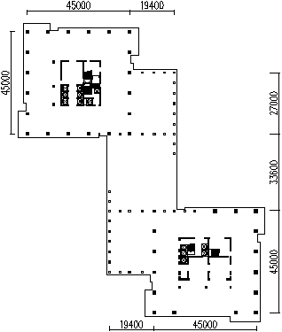
Figure 10. Linkbridge floor plane of Shenzhen Gemdale Viseen Tower.
Shenzhen Shirble the Prime has three towers A, B and C. Tower A is a 54-storey apartment with a building height of about 200m, Tower B is a 42-storey apartment with a building height of about 156m, and Tower C is a 52-storey office building with a building height of about 252m. Three towers all adopt a partially frame-supported shear wall structure.
There is a 2-story linkbridge with a span of about 18m on the 41st floor of Tower A connecting with Tower B, and a 2-story linkbridge with a span of 18~28m on the 31st floor of Tower C connecting with Tower B. The height of the 2 linkbridges is the same.
Due to the great difference in structural rigidity between the towers, the use of rigid connection will lead to complex structural forces, resulting in some structural components are unfavorable.
Both ends of the linkbridges adopt flexible connections, or one end adopts a rigid connection and the other end adopts a flexible connection, which can reduce the adverse effects brought by rigid connections. See Figure 11 for the floor plan of the linkbridges.
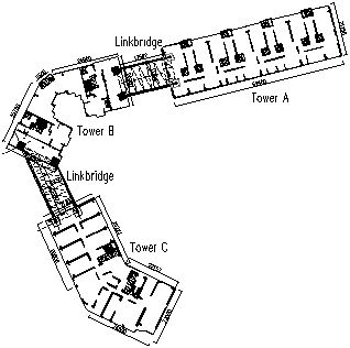
Figure 11. Linkbridge floor plane of Shenzhen Shirble the Prime.

4.6. The High-Rise Building with Concave-Convex Irregular Plan

In recent years, many high-rise buildings with concave-convex irregular plan have emerged, which have better architectural lighting, ventilation and landscape effects. Based on the design experience and research results of such structures in Shenzhen in recent years, the following design points are summarized.
1) This type of structure is composed of a central area structure and wing structures extending in different directions, which are connected by diaphram to form a complete structure.
2) The wing structure is connected as a whole through the central area structure to jointly resist wind and horizontal earthquake effects. The height-width ratio of the structure should be calculated based on the projected total length of the wing structure extension length in the lateral direction.
3) The lateral stiffness of the structure is primarily provided by the shear walls in the central area structure.
4) The wing structure often have shear walls arranged in one direction, and it should be analyzed as a less shear walls in one direction structure.
5) It should be ensured that the weakly connected diaphram (including the root zone of the wing structure) satisfies the bending and shear load-bearing capacity.
6) It is desirable to control the aspect ratio of the wing structurte to meet the wind-induced vibration acceleration limit in the corners of the floor plan.
A super high-rise residential building in Shenzhen has a height of 149m, 45 floors above ground, with a beam-type transfer floor at the 4th floor, adopting a partially frame-supported shear wall structure.
The floor plan of the standard floor structure is shown in Figure 12. From the central area structure formed by the elevator room and stairwell, three wing structures extend outward. For this structure, a detailed analysis of the stress of the wing structures is required. Wing structures are analyzed and calculated as a less shear walls in one direction structure. At the same time, a detailed analysis of weakly connected diaphrams between the central area and wing structures were conducted to ensure structural safety.
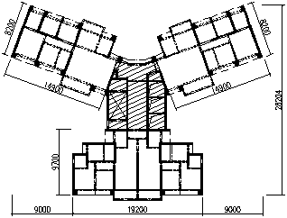
Figure 12. Standard floor plane of a super high-rise residential building in Shenzhen.

4.7. Mega Structures with Belt Trusses

As the main lateral force-resisting components, belt trusses and outrigger trusses are generally set up in refuge floor. The main role of the ring belt trusse is to bear the vertical load transmitted from the columns on upper floor. Furthermore, it increases the lateral stiffness of the structure and shares the lateral shear force with the core-wall.
In actual engineering, it should be determined based on needs whether the outrigger truss and the belt truss should be set on the same floor. The belt truss can be set up independently; when the outrigger truss must be set up, the belt truss can be set up at the same time.
The belt truss can be arranged in a single or double bays. When single-bay ring belt truss is used, the adverse effect of truss eccentricity on mega columns should be considered. When double-bay ring belt trusses are used, it is advisable to understand the main functions and force characteristics of double-bay ring belt trusses and to justify their necessity and effectiveness.
Table 3 lists examples of super high-rise buildings with belt trusses. The current JGJ should provide relevant design provisions for belt trusses.
Table 3. Examples of super high-rise buildings with belt trusses.

Project name

Structural system

Belt truss arrangement

Shanghai Tower

frame–core wall structure with mega columns & six-bay outrigger truss & belt truss

Two-bay belt trusses (not fully enclosed)

Guangzhou CTF Finance Centre

frame–core wall structure with mega columns & four-bay outrigger truss & belt truss

Two-bay belt trusses

Shenzhen Ping An Finance Center

frame–core wall structure with mega columns & four-bay outrigger truss & belt truss

Two-bay belt trusses and one-bay belt trusses in the coner of the plan, with one-bay belt trusses set up in some refuge floor

Suzhou Zhongnan Center

frame–core wall structure with mega columns & outrigger truss & belt truss

Two-bay belt trusses and one-bay belt trusses in the coner

Shenzhen Qianhai Financial Centre

frame–core wall structure with mega columns & outrigger truss & belt truss

One-bay belt trusses

Shenzhen UpperHills

frame–core wall structure with mega columns & belt truss

One-bay belt trusses, some of them are spanning two stories

Shenzhen OCT Tower

frame–core wall structure with mega columns & belt truss & mega brace

One-bay belt trusses

5. Design Methods for Rare Earthquakes
The design method for rare earthquakes should include the following:
1) Plastic deformation of structural members may occur under the action of rare earthquakes. Therefore, the calculation method should accurately calculate their plastic deformation and internal forces.
2) Calculate the shear and axial compression capacity of the main lateral force-resisting vertical members to meet the safety requirements. Control the plastic deformation of the energy-dissipative components not to exceed the limit value.
Currently, the more commonly used dynamic elastic-plastic analysis software includes non-Chinese software such as Perform-3D, ABAQUS, MIDAS, etc., and Chinese software such as PBSD, PKPM, YJK, SAUSAGE, and STRAT, etc.
Some analyzing software is not yet able to provide calculations of the shear and axial compressive capacities of the main lateral force-resisting members. The internal force calculation results of the main members of different software vary greatly. And when the shear wall appears to be in full-section tension, the current analysis method is not yet perfect.
Under the action of a rare earthquake, a supplementary analysis can be conducted using a model that does not consider the elastic-plastic behavior of structural components. However, the stiffness of the structural components should be adjusted according to their damage state, which can be determined through dynamic elastic-plastic analysis. Additionally, the base shear force of the model should be essentially consistent with the results calculated by static pushover or dynamic time-history elastic-plastic analysis.
6. Conclusion
Current building structure codes are the basis for the design of high-rise buildings and is the crystallization of the wisdom of previous generations. However, the emergence of various new types of building structures has brought many challenges to structural design. Therefore, the current codes still need further research, innovation, supplementation, and development. This awaits the unremitting efforts of contemporary people to keep pace with the times and contribute to the enrichment and development of the building structure codes.
Abbreviations
Old version JGJ: Technical Specification for Concrete Structures of Tall Building” (JGJ 3-2002)
Current JGJ: Technical Specification for Concrete Structures of Tall Building” (JGJ 3-2010)
2005 version D BJ/T5: Technical Specification for Concrete Structures of Tall Building” (D BJ/T5-46-2005)
2013 version D BJ/T5: Technical Specification for Concrete Structures of Tall Building” (D BJ/T5-46-2005)
Acknowledgments
I would like to express my sincere gratitude to Luo Jiajun for their meticulous translation work. Their dedication and expertise greatly contributed to the clarity and accuracy of the English version of this paper.
Conflicts of Interest
All the authors do not have any possible conflicts of interest.
References
[1] Technical Specification for Concrete Structures of Tall Building: JGJ 3-2002 [S]. Beijing: China Architecture & Building Press, 2002.
[2] Technical Specification for Concrete Structures of Tall Building: JGJ 3-2010 [S]. Beijing: China Architecture & Building Press, 2011.
[3] Wei Lian, Gong Zhaoji, Sun Huizhong, et al. Several Issues in the Structural Design of Di Wang Building [J]. Building Structure, 2000, 30(6): 31-36.
[4] Xie Zhuangning, Xu An, Wei Lian, etc. Study on Full-scale Measurements of Wind-induced Response of the Shenzhen Kingkey 100 Tower [J]. Journal of Building Structures, 2016, 37(6): 8.
[5] Supplementary Provisions to the Technical Specification for Concrete Structures of Tall Buildings in Guangdong Province (JGJ 3-2002): DBJ/T5-46-2005 [S]. Beijing: China Architecture & Building Press, 2005.
[6] Technical Specification for Concrete Structures of Tall Building: DBJ 15-92-2013 [S]. Beijing: China Architecture & Building Press, 2013.
[7] Wang Sen, Wei Lian, Li Yanfeng. Design of Super High-rise Building Structure of Hollow Large Slab without Beam in Shenzhen Qianhai International Financial Center, Shenzhen [J]. Building Structure, 2020, 50(21): 6-13.
[8] Wei Lian, Shi Gang, Wang Sen. Aseismic Design of Shenzhen Newworld Business Center (I) [J]. Building Structure, 2006, 28(1): 66-71.
[9] Wei Lian, Shi Gang, Wang Sen. Aseismic Design of Shenzhen Newworld Business Center (II) [J]. Building Structure, 2006, 28(2): 40-45.
[10] Wei Lian, Liu Weiya, Wang Sen, et al. Discussion on Problems of OCT (Shenzhen) Tower structural design [J]. Building Structure, 2015, 45(20): 1-7.
[11] Wei Lian, Wang Sen, Liu Guanwei, etc. Structural design of super high-rise buildings with super height width ratio in tower B and C of Shenzhen Hengyu Houhai Financial Center [J]. Building Structure, 2023(22): 20-25.
[12] Wei Lian, Zeng Qingli, Wang Sen. Seismic Design and Calculation Methods of High-rise Shear Wall Structure with Few Shear Walls in One Direction [J]. Building Structure, 2020, 50(7): 1-8.
[13] Qu Tao, Wei Wen, Li Lun, etc. Structural design of sky corridors for SuiBao International Exhibition Center [J]. Building Structure, 2022, 52(23): 6.
[14] Wei Lian, Luo Jiajun, Wang Sen. Mechanical Behavior of Weakly Connected Diaphragm of High-rise Structure with Concave-convex Irregular Plan under Horizontal Earthquake Action [J]. Building Structure, 2023(22): 1-5.
[15] Wei Lian, Luo Jiajun, Wang Sen. Internal Force Analysis Method for Weakly Connected Diaphragm of High-rise Structure with Concave-convex Irregular Plane under Horizontal Earthquake Action [J]. Building Structure, 2023(22): 6-11.
[16] Wei Lian, Luo Jiajun, Wang Sen. Seismic Design Method for Weakly Connected Diaphragm of High-rise Structure with Concave-convex Irregular Plane under Horizontal Earthquake Action [J]. Building Structure, 2023(22): 12-19, 11.
Cite This Article
  • APA Style

    Lian, W., Sen, W. (2024). Building Structural Design Innovation and Code Development. International Journal of Architecture, Arts and Applications, 10(1), 9-19. https://doi.org/10.11648/j.ijaaa.20241001.12

    Copy | Download

    ACS Style

    Lian, W.; Sen, W. Building Structural Design Innovation and Code Development. Int. J. Archit. Arts Appl. 2024, 10(1), 9-19. doi: 10.11648/j.ijaaa.20241001.12

    Copy | Download

    AMA Style

    Lian W, Sen W. Building Structural Design Innovation and Code Development. Int J Archit Arts Appl. 2024;10(1):9-19. doi: 10.11648/j.ijaaa.20241001.12

    Copy | Download

  • @article{10.11648/j.ijaaa.20241001.12,
      author = {Wei Lian and Wang Sen},
      title = {Building Structural Design Innovation and Code Development},
      journal = {International Journal of Architecture, Arts and Applications},
      volume = {10},
      number = {1},
      pages = {9-19},
      doi = {10.11648/j.ijaaa.20241001.12},
      url = {https://doi.org/10.11648/j.ijaaa.20241001.12},
      eprint = {https://article.sciencepublishinggroup.com/pdf/10.11648.j.ijaaa.20241001.12},
      abstract = {In recent years, Some new structural systems and design difficulties of high-rise and super high-rise buildings were emerged in Shenzhen, such as forced displacement and non-forced displacement, story lateral stiffness calculation method, frame-core wall structures with partial perimeter frame beams missing, super high-rise structure with great height-width ratio, high-rise less shear walls in one direction structure, conjoined tower structures, high-rise structure with inclined column, mega structure with belt truss, rare earthquake design method etc. The emergence and solution of these problems reflect the innovation of the structural design of high-rise buildings. Meanwhile, Structural design has encountered many difficulties and new problems. The solutions to these problems sometimes conflict with the current Chinese code, or there are no relevant provisions in the Chinese code. The current Chinese code is the basis for designing of high-rise buildings, which is the crystallization of the wisdom of previous generations, but the emergence of various new types of building structures has brought about numerous difficulties in structural design. Therefore, during the design process, it is necessary to conduct research, innovation, supplementation, and development of the current code. In view of this situation, this paper combines the previous engineering practical experience and introduces some structural design points of complex super high-rise buildings located in Shenzhen. It is for designers' reference, which also provides content for the revision of the specification.},
     year = {2024}
    }
    

    Copy | Download

  • TY  - JOUR
    T1  - Building Structural Design Innovation and Code Development
    AU  - Wei Lian
    AU  - Wang Sen
    Y1  - 2024/04/02
    PY  - 2024
    N1  - https://doi.org/10.11648/j.ijaaa.20241001.12
    DO  - 10.11648/j.ijaaa.20241001.12
    T2  - International Journal of Architecture, Arts and Applications
    JF  - International Journal of Architecture, Arts and Applications
    JO  - International Journal of Architecture, Arts and Applications
    SP  - 9
    EP  - 19
    PB  - Science Publishing Group
    SN  - 2472-1131
    UR  - https://doi.org/10.11648/j.ijaaa.20241001.12
    AB  - In recent years, Some new structural systems and design difficulties of high-rise and super high-rise buildings were emerged in Shenzhen, such as forced displacement and non-forced displacement, story lateral stiffness calculation method, frame-core wall structures with partial perimeter frame beams missing, super high-rise structure with great height-width ratio, high-rise less shear walls in one direction structure, conjoined tower structures, high-rise structure with inclined column, mega structure with belt truss, rare earthquake design method etc. The emergence and solution of these problems reflect the innovation of the structural design of high-rise buildings. Meanwhile, Structural design has encountered many difficulties and new problems. The solutions to these problems sometimes conflict with the current Chinese code, or there are no relevant provisions in the Chinese code. The current Chinese code is the basis for designing of high-rise buildings, which is the crystallization of the wisdom of previous generations, but the emergence of various new types of building structures has brought about numerous difficulties in structural design. Therefore, during the design process, it is necessary to conduct research, innovation, supplementation, and development of the current code. In view of this situation, this paper combines the previous engineering practical experience and introduces some structural design points of complex super high-rise buildings located in Shenzhen. It is for designers' reference, which also provides content for the revision of the specification.
    VL  - 10
    IS  - 1
    ER  - 

    Copy | Download

Author Information
  • Shenzhen Li Peng Structural Engineering Technology Co., Ltd., Shenzhen, China

  • Shenzhen Li Peng Structural Engineering Technology Co., Ltd., Shenzhen, China