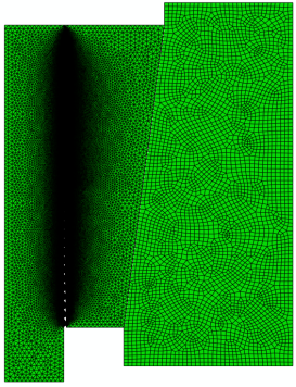
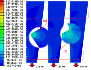
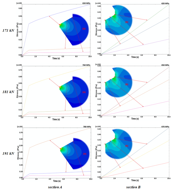
The anchor system plays a very important part of the prestressed structure, that contacts and transmits force to the cables when stretching to create residual stress. The operating conditions of the anchor system in general and the anchor core in particular are extremely harsh. In this paper, ABAQUS software was applied to model and numerically simulate the axisymmetric loading process of the anchor core in manufacturing prestressed concrete sleepers, to study the effects of tensile forces to the pressure resistance of the cylinder. To verify the analytical results, a Finite Element (FE)-model with the same material and geometrical properties was created. The difference is the assumption of plane stress in the analytical solution, can be solved using two - dimensional finite elements, which are most conveniently described in cylindrical (r, θ, z) coordinates. This articles also especially focused on calculating the change of stress on the edges of the anchor core teeth with different tensile forces. We also refered to experimental results to get data on traction force and working conditions to build a calculation model and select input parameters. Comparison of the stress generated on the teeth of the anchor core was performed with three different tensions of 171, 181 and 191 kN. The maximum and concentrated stress at the top and root of the anchor core when tensioning the cable has been calculated.
| Published in | Advances in Materials (Volume 13, Issue 2) |
| DOI | 10.11648/j.am.20241302.12 |
| Page(s) | 31-36 |
| Creative Commons |
This is an Open Access article, distributed under the terms of the Creative Commons Attribution 4.0 International License (http://creativecommons.org/licenses/by/4.0/), which permits unrestricted use, distribution and reproduction in any medium or format, provided the original work is properly cited. |
| Copyright |
Copyright © The Author(s), 2024. Published by Science Publishing Group |
Finite Element Axisymmetric Simulation, Finite Element Method, Abaqus, Tensional Forces, Stress Distribution, Effective Stress, Conical Wedge Anchorage
Material Properties | C45 | SCM420 |
|---|---|---|
Young’s Modulus, E | 2e+11 | 2.09e+11 |
Poisson ratio, v | 0.3 | 0.33 |
FEM | Finite Element Method |
FE | Finite Element |
3D | A Three-Dimensional |
CAX3 | The Three-Node Axisymmetric Element Type |
| [1] | ACI, 2001, “Specification for Unbonded Single-Strand Tendons and Commentary,” American Concrete Institute 423.6-01, Farmington Hills, MI, 29 pp., ISBN 0-7031-063-1. |
| [2] | ACI, 2004, “Prestressing Concrete Structures with FRP Tendons,” American Concrete Institute 440.4R-04, Farmington Hills, MI, 35 pp., ISBN 0-87031-166-2. |
| [3] | ACI, 2008a, “Guide for the Design and Construction of Externally Bonded FRP Systems for Strengthening Concrete Structures,” American Concrete Institute 440.2R-08, Farmington Hills, MI, 76 pp., ISBN 978-0-87031-285-4. |
| [4] | ACI, 2008b, “Building Code Requirements for Structural Concrete and Commentary,” American Concrete Institute 318M-08, Farmington Hills, MI, 471 pp. ISBN 978-0-97031-283-0. |
| [5] | Shrive N. G., Sayed-Ahmed E. Y., Damson E., “Tilleman and G. Tadros, Prestressing anchorage system for fibre reinforced plastic prestressing tendons”, U.S. Patent Application 08/754186, 1996. |
| [6] | Sayed-Ahmed E. Y., Shrive N. G., “A new steel anchorage system for post-tensioned applications using carbon fibre reinforced plastic tendons”, Canadian Journal of Civil Engineering, V. 25, No 1, 1998, pp. 113-127. |
| [7] | Campbell T. I., Keatley J. P. and Barnes K. M., “Analysis of an anchorage for CFRP prestressing tendons”, Annual Conference of the Canadian Society for Civil Engineering, Canada, 1998, pp. 551-560. |
| [8] | Perry J., Aboudi J., “Elastic-plastic stresses in thick-walled cylinders”, ASME J. Pressure Vessel Technology, 2003, Vol. 125, pp. 248-252. |
| [9] | Zhao W., Seshadri R. and Dubey R. N., “On thick-walled cylinder under internal pressure”, ASME J. Pressure Vessel Technology, 2003, Vol. 125, pp. 267-273. |
| [10] | Al-Mayah A., Soudki K. A., and Plumtree A., “Experimental and analytical investigation of a stainless steel anchorage for CFRP prestressing tendons”, March-April 2001, PCI Journal, pages 88–100. |
| [11] | Al-Mayah A., Soudki K. A., and Plumtree A., Novel anchor system for CFRP rod: “Finite-element and mathematical models”, Sept./Oct. 2007, J. of Compos. for Constr., pages 469–476. |
| [12] | Schmidt, J. W., S. T. Smith, B. Taljsten, A. Bennitz, P. Goltermann, and H. Pedersen. 2011. “Numerical simulation and experimental validation of an integrated sleeve-wedge anchorage for CFRP rods.” J. Compos. Constr. 15(3): 284–292. |
| [13] | Wang, X., P. Xu, Z. Wu, and J. Shi. 2015a. “A novel anchor method for multi-tendon FRP cable: Concept and FE study.” Compos. Struct. 120: 552–564. |
| [14] | Wang, X., P. Xu, Z. Wu, and J. Shi. 2015b. “A novel anchor method for multitendon FRP cable: Manufacturing and experimental study.” J. Compos. Constr. 19(6): 04015010. |
| [15] | D’amore, A., Grassia, L., Ceparano, A. 2016. “Correlations between Damage Accumulation and Strength Degradation of Fiber Reinforced Composites Subjected to Cyclic Loading.” Procedia Eng. 167, 97–102. |
| [16] | Shiri, S., Yazdani, M., Pourgol-Mohammad, M. 2015. “A fatigue damage accumulation model based on stiffness degradation of composite materials.” Mater. Des., 88, 1290–1295. |
| [17] | Guerrero, J., Mayugo, J., Costa, J., Turon, A. 2018, “A 3D Progressive Failure Model for predicting pseudo-ductility in hybrid unidirec- tional composite materials under fibre tensile loading.” Compos. Part A Appl. Sci. Manuf. 107, 579–591. |
| [18] | Chen, X., Sun, X., Chen, P., Wang, B., Gu, J.; Wang, W., Chai, Y., Zhao, Y. 2021. “Rationalized improvement of Tsai–Wu failure criterion considering different failure modes of composite materials.” Compos. Struct., 256, 113120. |
| [19] | Chieu L. T.,, Quang P.,, Nghiep D., M., Modeling of the displacement and pressure effects in a conical wedge andchorage using finite element method (FEM), J. of Science and Technology No. 5A, pp. 169-176, (10/2013), ISSN 0866-708X. |
| [20] | Quang P., Trang N., V., Vinh N., T., Thu H., T., 3D numerical simulation of effective stress in conical (steel) wedge anchorage by finite element method (FEM), J. of Science and Technology No. 5A, pp. 208-216, (10/2013), ISSN 0866-708X. |
| [21] | Abaqus/CAE, “User’s Manual”. |
| [22] | Abaqus, Example Problems Manual Volume I: “Static and Dynamic Analyses”. |
| [23] | Brandes E. A., “Smithells metals reference book”, 1983, Butterworths. |
APA Style
Quang, P. (2024). Finite Element Axisymmetric Models for Conical Wedge Anchorage Used in the Production of Prestressed Steel Reinforced Concretes. Advances in Materials, 13(2), 31-36. https://doi.org/10.11648/j.am.20241302.12
ACS Style
Quang, P. Finite Element Axisymmetric Models for Conical Wedge Anchorage Used in the Production of Prestressed Steel Reinforced Concretes. Adv. Mater. 2024, 13(2), 31-36. doi: 10.11648/j.am.20241302.12
@article{10.11648/j.am.20241302.12,
  author = {Pham Quang},
  title = {Finite Element Axisymmetric Models for Conical Wedge Anchorage Used in the Production of Prestressed Steel Reinforced Concretes
},
  journal = {Advances in Materials},
  volume = {13},
  number = {2},
  pages = {31-36},
  doi = {10.11648/j.am.20241302.12},
  url = {https://doi.org/10.11648/j.am.20241302.12},
  eprint = {https://article.sciencepublishinggroup.com/pdf/10.11648.j.am.20241302.12},
  abstract = {The anchor system plays a very important part of the prestressed structure, that contacts and transmits force to the cables when stretching to create residual stress. The operating conditions of the anchor system in general and the anchor core in particular are extremely harsh. In this paper, ABAQUS software was applied to model and numerically simulate the axisymmetric loading process of the anchor core in manufacturing prestressed concrete sleepers, to study the effects of tensile forces to the pressure resistance of the cylinder. To verify the analytical results, a Finite Element (FE)-model with the same material and geometrical properties was created. The difference is the assumption of plane stress in the analytical solution, can be solved using two - dimensional finite elements, which are most conveniently described in cylindrical (r, θ, z) coordinates. This articles also especially focused on calculating the change of stress on the edges of the anchor core teeth with different tensile forces. We also refered to experimental results to get data on traction force and working conditions to build a calculation model and select input parameters. Comparison of the stress generated on the teeth of the anchor core was performed with three different tensions of 171, 181 and 191 kN. The maximum and concentrated stress at the top and root of the anchor core when tensioning the cable has been calculated.
},
 year = {2024}
}
TY  - JOUR
T1  - Finite Element Axisymmetric Models for Conical Wedge Anchorage Used in the Production of Prestressed Steel Reinforced Concretes

AU  - Pham Quang
Y1  - 2024/06/27
PY  - 2024
N1  - https://doi.org/10.11648/j.am.20241302.12
DO  - 10.11648/j.am.20241302.12
T2  - Advances in Materials
JF  - Advances in Materials
JO  - Advances in Materials
SP  - 31
EP  - 36
PB  - Science Publishing Group
SN  - 2327-252X
UR  - https://doi.org/10.11648/j.am.20241302.12
AB  - The anchor system plays a very important part of the prestressed structure, that contacts and transmits force to the cables when stretching to create residual stress. The operating conditions of the anchor system in general and the anchor core in particular are extremely harsh. In this paper, ABAQUS software was applied to model and numerically simulate the axisymmetric loading process of the anchor core in manufacturing prestressed concrete sleepers, to study the effects of tensile forces to the pressure resistance of the cylinder. To verify the analytical results, a Finite Element (FE)-model with the same material and geometrical properties was created. The difference is the assumption of plane stress in the analytical solution, can be solved using two - dimensional finite elements, which are most conveniently described in cylindrical (r, θ, z) coordinates. This articles also especially focused on calculating the change of stress on the edges of the anchor core teeth with different tensile forces. We also refered to experimental results to get data on traction force and working conditions to build a calculation model and select input parameters. Comparison of the stress generated on the teeth of the anchor core was performed with three different tensions of 171, 181 and 191 kN. The maximum and concentrated stress at the top and root of the anchor core when tensioning the cable has been calculated.

VL  - 13
IS  - 2
ER  -
School of Materials Science and Engineering, Hanoi University of Science and Technology (HUST), Hanoi, Viet Nam
Biography: Pham Quang is a Associate Professor at Hanoi University of Science and Technology, Faculty of Materials Engineering. He completed his PhD in Applied Materials Engineering from Chungnam National University (Korea) in 2008, and Postdoctoral research at the Technical University Dresden (Germany) in 2015-2016. Recognized for his exceptional contributions, Dr. Pham has been appointed to the title of Associate Professor, Senior Lecturer in December 2022 at Hanoi University of Science and Technology. He has participated in multiple international research collaboration projects in recent years. He currently serves on the Editorial Boards of numerous publications and has been invited as a Keynote Speaker, Technical Committee Member, Session Chair, and Judge at international conferences.
Research Fields: To study the science and technology of nano materials. To study and manufacture materials and composite materials with high durability, such as: metals and light alloys (Aluminium, Magnesium, Titanium) and nanotube carbon fiber reinforced metal/carbon fiber composites by plastic deformation intense (SPD) to create materials with nano and micro structures. To study the metal forming deformation of solid, Semi-solid. To study the FVM, FEM for modeling and computational materials science: including ABAQUS, ANSYS-FLUENT, COMSOL MULTIPHISICS, ANSYS, DEFORM 2D & 3D, MSC.MARC and MSC.SUPERFORGE.

Information