Research Article | | Peer-Reviewed

Mapping the Orientation and Distribution of Defects for the Natural Casting of 2,4,6-Trinitrotoluene (TNT) in 10kg Anti-tank Landmine Mold

Received: 30 January 2025     Accepted: 19 February 2025     Published: 6 March 2025
Views:       Downloads:
Abstract

2,4,6-Trinitrotoluene (TNT) is an explosive that is well known for its stable nature, performance, and reliability. It is used in the military and mining industries as it can be cast into various shapes due to its ease of processing at its melting temperature of 80 to 82°C. It can be processed safely within melting temperature without the risk of thermal and impact-related initiation. Despite these properties, casting defect-free charges of uniform density is challenging. Hence, there is a need for targeted quality control measures and process optimisation to minimise density variations and defect formation in manufacturing. In this work the defects formation is mapped for a 10 kg anti-tank landmine, this is done by melting and casting TNT into a 10 kg anti-tank landmine fibre glass mould without any controlled cooling method. The melting and cooling temperature profiles of the TNT casing process were manually monitored using an infrared camera and the process was simulated using COMSOL Multiphysics. The resulting cast was characterised by Vidisco foXRayzor Digital X-Ray and Irdium-192 (192lr) radioactive source. The findings from this study depicted a dense structure at the mould’s margins compared to the booster centre. The less dense area also showed a high proportion of defects which were attributed to shrinkage during cooling.

Published in American Journal of Science, Engineering and Technology (Volume 10, Issue 1)
DOI 10.11648/j.ajset.20251001.13
Page(s) 27-39
Creative Commons

This is an Open Access article, distributed under the terms of the Creative Commons Attribution 4.0 International License (http://creativecommons.org/licenses/by/4.0/), which permits unrestricted use, distribution and reproduction in any medium or format, provided the original work is properly cited.

Copyright

Copyright © The Author(s), 2025. Published by Science Publishing Group

Keywords

2,4,6-Trinitrotoluene, Anti-tank, Melt and Cast, Casting Defects, Mapping

1. Introduction
Energetic materials (EMs) are organic and inorganic molecules or formulations that store energy that gets released during deflagration or detonation upon initiation . EMs are classified as pyrotechnics, propellants, and explosives and are applied mainly in the aerospace, mining industry, and millitary. Ideally, the desired EMs should have higher detonation performance, lower sensitivity, and good thermal stability . However, high detonation performance and low sensitivity are not easy to achieve, but a good balance between these properties has been the focus of research .
Melt casting and mechanical pressing are among the most widely used methods for explosives processing and production. The melt casting is particularly ideal for large-scale munitions filling due to its cost-effectiveness. This method requires relatively modest capital equipment and is well-suited for automation . Melt and casting of EMs involves heating of EM flakes to a melting temperature of less than 100°C. At this temperature, the material is liquid phase and then poured into ammunition moulds or articles.
One of the oldest explosives, 2,4,6-Trinitrotoluene (TNT), was widely used during both the First and Second World Wars . Today, it remains the most readily available explosive worldwide and is extensively employed in producing melt-cast explosives. The molecular structure of TNT makes it chemically stable and moderately sensitive to impact and friction. With a melting point of 80-82°C, it can be safely melt-casted alone or mixed with other explosives, and cast into artillery shells and mines . TNT has low viscosity making it possible to still load solids like RDX into it, it can remain solidified even in adversely hot environments or climates . Thermal and chemical stability make it safe to process and handle. It also boasts good physical properties and compatibility with other explosives. However, it has the drawback of low density, low detonation velocity, 11-12 % shrinkage while it solidifies and incomplete oxidation upon detonation due to a negative oxygen balance, these parameters can impact its performance .
Modern explosive systems commonly utilise melt-cast EMs such as TNT, 2,4-dinitro-2,4-diazapentane (DNP), 2,4-dinitrotoluene (DNT), 2,4-dinitroanisole (DNAN), and 2,4,6-trinitroanisole (TNAN). Crystalline fillers like 1,3,5,7-tetranitro-1,3,5,7-tetraazacyclooctane (HMX), 1,3,5-trinitro-1,3,5-triazacyclohexane (RDX), and 2,4,6,8,10,12-hexanitro-2,4,6,8,10,12-hexaazaisowurtzitane (HNIW) are also incorporated into these systems . The melt-cast explosives are mainly used in a variety of munitions, including mortars, grenades, artillery shells, warheads, and antipersonnel mines .
Properties of an ideal melt-cast explosive or its formulations should include the following: (i) a good melting point ranging from 70 to 120°C, (ii) low vapor pressure of the material, (iii) a sufficient charge separation between melting point and the start of chemical decomposition, (iv) no casting defects (shrinking and cracking) during cooling, (v) no separation from the shell or casing due to significant shrinking, (vi) denser material with better explosive performance (detonation pressure and velocity), (vii) Insensitive (no premature detonation) and (viii) greener synthesis .
The shrinkage of TNT cast while it solidifies is the main cause of observed defects during the manufacturing and processing of TNT-based explosive weapons. These defects lead to poor performance as these create hot spots during detonation. Depending on the cooling rate and heat flow, these defects can form anywhere within the 3D space of the explosive charge. They can take a certain 3D shape or just form randomly, and this is determined by the shape of the casting mold. Knowing the 3D shape for the low-density areas or defects region is key in designing a controlled colling mechanism that can lead to cavity-less TNT explosive charge. This information is also useful in simulating effective cooling and heat flow for the cavity-less charge. Herein, we have mapped the defects formation for the natural casting of TNT into a 10 kg anti-tank landmine, this was done by monitoring and simulating the cooling profile. The resulting TNT charges were scanned using an x-ray and gamma rays.
2. Materials and Methods
2.1. TNT Casting
A normal casting approach was conducted, which involved melting 10-11 kg TNT flakes into the steam-heated aluminium pot, the molten material was then poured into a 10 kg antitank landmine mold and allowed to cool down to room temperature. The mold used during the casting is made of fiberglass material. During this process, a C5 FLIR infrared camera was used to record and determine the casting temperature (heating and cooling) of the TNT.
2.2. Temperature Monitoring Using Simulation Method
COMSOL Multiphysics 5.6 was used to simulate the heat transfer and heat gradient for TNT casting . Thermal properties of aluminium are available from COMSOL database, but TNT and fiberglass were obtained from literature and added manually . The dimensions of the 10 kg TNT mold are 3: 1 (97 mm: 290 mm). Figure 7 shows the 2D input dimensions for the COMSOL simulation. The materials were assigned to the wall, interior (between the centre rod and the wall) and center rod. Fiberglass and aluminium were used as materials for the mold, and for each material, two conditions were tested which were room temperature and preheated to the same temperature as the TNT. The room temperature of the mold was set to be 24°C and the preheated mold was set to 84°C. The TNT temperature was also set to be 84°C initially and it was assumed to be uniform throughout the TNT material before cooling.
2.3. Characterizing with X-ray and Iridium-192
The resulting casted TNT was scanned using the Vidisco foXRayzor Digital X-Ray. The images are presented in Figure 17 to Figure 20 and these are face-on and side-on images of the charge. The casted TNT was also characterised using gamma rays by using the Iridium-192 (192Ir) as a source, this method was able to give a single image of the explosive as shown below in Figure 21.
3. Results and Discussion
3.1. Simulation Results and Analysis
Figure 1 shows the 2D input dimensions for the COMSOL simulation. The mould height measured from the bottom to the top of the TNT charge is 102 mm and the radius measured from the centre to the outer end of the wall is 150 mm. The thickness of the mold is 5 mm. The dimensions of the encased 10 kg TNT are 97 mm in height and 145 mm in radius.
Figure 1. 2D Input dimensions.
The thermal properties of the materials used in this simulation are tabulated below Table 1.
Table 1. Thermal properties the materials used for simulation.

Material

Heat capacity at constant pressure [J.kg-1.K-1]

Thermal conductivity [W.m-1.K-1]

Density [kg.m-3]

References

Aluminium

900.0

238

2700

-----

TNT

1062.2

0.260

1648

Fibreglass

903.5

0.431

1835

Figure 2, gives the results obtained from the simulation with the mold initial temperature at 24°C. The red areas of the images are the parts of the materials at lower temperatures and the orange parts present the higher temperatures. The images are showing the change in temperature throughout the materials after 15, 75, 150 and 225 min. The higher temperature zone started as almost a rectangular shape and transformed into an oval shape as it cooled down, this forms an inner 3D doughnut shape within the TNT material. When the system cools to a lower temperature the oval is closer to the centre aluminium rod, which suggests a steep cooling profile towards the centre. Also, the edges of the charge seem to be cooling at a higher rate but not as compared to the centre. The reason the charge shows a steep cooling profile toward the centre is that the aluminium rod acts as a heat sink, taking heat out of the system.
Figure 2. Cooling profile of TNT.
Figure 3. 2D Isotherm contours during cooling.
The temperature contours in Figure 3 give more details on the temperature profile of TNT as it cools. The further line contours from each other imply a lower cooling gradient and the closer the lines imply a steeper cooling gradient. The cooling gradient from the top, bottom and closer to the centre rod is much steeper as compared to the side walls.
Point temperature profiles were also plotted; this is done by measuring the temperature at one point of the materials as it cooled. The point coordinates were selected as shown in Figure 4, the points were selected to compare the temperature at the wall, centre rod, top, bottom and mid. The temperature was plotted as a function of time for each of the coordinates. The plots were done for fiberglass and aluminium mold both at room temperature and at 84°C.
Figure 4. Temperature profile coordinates.
The x, y, z coordinates in Figure 4 are plotted in Figure 5 to Figure 8 with their differing initial conditions and mold materials. This was done to explore the effect of the preheating conditions and the mold material on the cooling profile of the TNT.
For Figure 5 the centre rod was preheated, and the mold was kept at room temperature, the material of the mold used here was fibreglass. It can be noticed from the plots that the centre aluminium rod cools very rapidly and in almost 15 min it is close to 30°C, the fibreglass mold warms up until it reaches 35°C, after which it cools down at a slower rate compared to the centre aluminium rod. Top cast, cast near walls and bottom cast close to the wall, they all cool at almost the same rate, and this confirms the doughnut shape cooling of the internal cast. The TNT cast at the centre of the doughnut (radius/2) cools at the slowest rate, it reaches almost 37°C at 300 min.
Figure 5. TNT cooling profile in fiberglass mold at 24°C.
Figure 6. TNT cooling profile in fiberglass mold preheated at 84°C.
In Figure 6 the effect of preheating the fibreglass mold to the cooling profiles is minimal, the cooling rate for the centre aluminium rod and fibreglass happens very fast to reach 35°C after which they cool slightly differently and slower. The impact of this is that the inner material (radius/2) cools slower and reaches almost 38-39°C in 300 min. In Figure 7 aluminium mold at room temperature was also explored and it can be observed that the cooling rate slightly becomes higher (cools faster) for surfaces as they are below 30°C at 300 min. The inner TNT seems to also cool slightly faster, and it reached 35°C at 300 min.
Figure 7. TNT cooling profile in Aluminium mold at 24°C.
Figure 8. TNT cooling profile in Aluminium mold preheated at 84°C.
The effect of preheating a metal mold does not show an effect on the cooling profile of the inner material, but the metal mold affects the cooling profile of the inner material. In Figure 7 and Figure 8 it can be noticed that the inner material reaches almost 35°C about 300 min.
From this simulation in can be extrapolated that a slightly different cooling profile throughout the material can be achieved through insulating mold materials, however, the downside of this is that it elongates the cooling time. On the other side the metallic mold can make the material cool fast which is suspected to cause a defect if the colling direction is not controlled.
3.2. Thermal Profile of the TNT Cast
A steam-heated pot is normally used in the casting of TNT at the DBEL casting facility. Figure 9 show the heating of TNT in the pot in preparation for the casting. These images give an idea of the temperature at which this operation is done. It can be noticed that the steam pipes can heat the pot up to 108°C. Once the TNT flakes are poured the temperature of the pot slightly drop as it loses the heat towards the melting of the material. From the infrared images, the background temperature is within 24.9 to 25.7°C, this is the normal ambient temperature during a hot summer in South Africa. This is the normal working temperature for the local processing facility.
Figure 9. Heating of steam pot and melting of TNT.
During the melting process, it was observed that the flakes can coagulate to form some bigger lumps which took time to completely melt.
Figure 10. TNT melting process before casting.
The time it took for 10 kg of TNT to mostly melt can be deduced from Figure 10, it can be seen from the graph that most of the TNT melted in about 10 min. After 10 min the steam was switched off and the TNT started to cool. The cooling takes a longer time as compared to the heating process, and this cooling was done naturally. For controlled cooling, this might take longer as the material is allowed to cool slowly.
The pouring of the TNT was done in two layers, and each was allowed to cool while poking the surface. Figure 11 shows the temperature of the mold (26.4°C) before pouring TNT, it can be noticed that the mold was slightly cold compared to the room temperature (29.7°C). The molten TNT was poured at 82°C, during the pouring the temperature of the mold increased to 77.8°C. The poking of the cast exposed the inner molten TNT which is picked by the camera as maximum temperature. Figure 12 is data extracted from a video of the first record. It can be seen that within 7 min the TNT cast cooled to 78°C, the random temperature fluctuations beyond 7 min are due to the poking done on the TNT surface which exposed the hotter inner TNT cast.
Figure 11. Pouring and casting of TNT (first layer).
Figure 12. Cooling of TNT while poking first layer record 1.
The data from the recording was also extracted and plotted against time and it is shown in Figure 13.
For both Figure 12 and Figure 13 there is nothing that can be concluded in terms of the cooling rate. This is due to the poking during the casting which caused the temperature to fluctuate between the solid surface and the inner molten TNT. The fluctuation for Figure 12 was between 78-82°C and for Figure 13 was between 69-80°C.
The radiometric images for the second layer of the TNT casting are shown in Figure 14. The images are almost like the ones in Figure 11, however, from these images, we can see the doughnut shape cooling of the TNT which implies that the cooling is from outside towards the centre. The cooling rate and cooling rate direction are important as they determine how and where the cavities occur in the solid TNT.
Figure 13. Cooling of TNT while poking first layer record 2.
Figure 14. Pouring and casting of TNT (second layer).
For records 1 and 2 the data was extracted and presented graphically shown in Figure 15 and Figure 16 above. The temperature fluctuation for record 1 is significant and varied between 74-82°C. Record 2, the fluctuation is minimum and the average cooling profile can be derived from this graph. Figure 10 and Figure 16 show curves with low fluctuation and these can be used to determine the cooling rate and for estimation of cooling time.
Figure 15. Cooling of TNT while poking second layer record 1.
Figure 16. Cooling of TNT while poking second layer record 2.
3.3. Characterisation of the Casted TNT Using X-ray
The resulting casted TNT was scanned using the x-ray equipment available at DBEL. The images are presented in Figure 17 and Figure 18 and these are face-on images of the charge. The resolution of the images was enhanced by varying the scanning energy of the x-ray. The resolution of the images is good enough since the X-ray was able to penetrate through the thickness of the charge as we could see the wire and the Lead labels which were positioned between the charge and the X-ray digital screen. In Figure 17 the lighter area of the image contains less density and the darker parts are denser the opposite is observed in Figure 18. It can be seen from the images, that there are areas with less density which can be characterised as casting defects (porosity, cracks, or cavity). One interesting aspect of this is that the charges are denser at the outer edges and at the centre. The part of the charge that is less dense appears to form a doughnut area around the centre of the charge. This can be correlated to the cooling profile and cooling rate of the TNT which also follows the same trend.
Figure 17. X-ray image for the casted TNT positive image (face on).
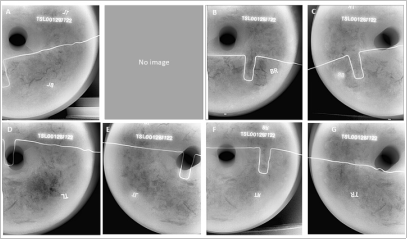
Figure 18. X-ray image for the casted TNT negative image (face on).
The side on x-ray scans were also done to view the defect on the sides, the scans were done per 90° rotation of the charge Figure 19 and Figure 20. For this orientation the x-rays should pass through the bulkier mass of the charge and for this to happen more energy is required to pass through the thick material. The resulting images are not as good as the side in terms of the resolution. The lead labels for the images cannot be identified properly due to the orientation of the charge. Though these images cannot be assigned to the charge angle of rotation there are noticeable defects. There is what appears as a faint horizontal line across the charge, however, this is only seen in one image. For images in Figure 19 there is what appears as porosity on the right bottom edge of the images and for Figure 20 this appears on the left bottom edge. These defects are not well resolved when compared to the face-on.
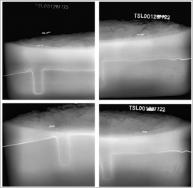
Figure 19. Side on X-ray image for the casted TNT negative image, (0o rotation).
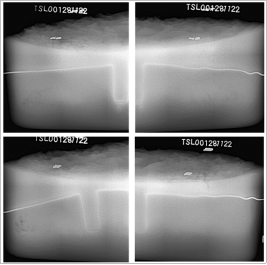
Figure 20. Side on X-ray image for the casted TNT negative image (90o rotation).
Characterisation of the casted TNT using Iridium-192 (192Ir)
The casted TNT was also characterised using gamma rays by using the iridium-192 as a source, this device was able to give a single image of the explosive as shown in Figure 21. This method gave a good image with low resolution as compared to the X-ray method. The fine details of explosive defects were not clearly seen for this method.
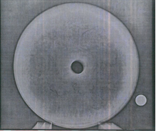
Figure 21. Explosive image obtained by gamma method.
4. Conclusions
The shape of the 10 kg antitank mine explored here is cylindrical with a diameter-to-height ratio of 3: 1 (diameter = 291 mm, height 97 mm). This work shows that the natural casting of TNT to the shape of a 10 kg antitank mine naturally is complex as it always results in the formation of casting defects. For the materials used, both simulation and experimental show that the cooling is from the circumference towards the centre and from the centre rod towards the circumference. This resulted in the formation of 3D doughnut shape cooling towards the centre. This doughnut shape cools very slowly as solid TNT isolates it from both ends. From the x-ray data, the doughnut shape is observed, and it appears as a low-density area. This suggests that slow cooling can result in low-density, and it can result in low performance of the charge. Controlled slow cooling appeals to be the best option for reducing defects, however, it can result in low-density areas. The controlled cooling that can work with this system is directional cooling, where heating and cooling are on opposite sides of the shape of the material. The cooling can be from the bottom up or from outside in.
Abbreviations

TNT

2,4,6-Trinitrotoluene

EMs

Energetic materials

RDX

1,3,5-trinitro-1,3,5-triazacyclohexane

DNP

2,4-dinitro-2,4-diazapentane

DNT

2,4-dinitrotoluene

DNAN

2,4-dinitroanisole

TNANA

2,4,6-trinitroanisole

HMX

1,3,5,7-tetranitro-1,3,5,7-tetraazacyclooctane

HNIW

2,4,6,8,10,12-hexanitro-2,4,6,8,10,12-hexaazaisowurtzitane

Acknowledgments
This work was made possible by the Parliamentary Grant fund through the Council of Scientific and Industrial Research (CSIR) research and development. The support for the execution of this work was made possible by the Landward Sciences Impact Area Manager our respective Business Development Manager and the Research Group Leader.
Author Contributions
Lamla Thungatha: Methodology, Supervision, Writing – original draft, Writing – review & editing
Nobuhle Nyembe: Formal Analysis, Project administration, Visualization, Writing – review & editing
Tshepo Qhamakwane: Investigation, Resources
Conrad Mahlase: Conceptualization, Formal Analysis, Funding acquisition, Writing – review & editing
Lisa Ngcebesha: Data curation, Investigation, Software, Visualization
Funding
This work was made possible by the Parliamentary Grant fund through the Council of Scientific and Industrial Research (CSIR) research and development. This work is not supported by any external funding.
Conflicts of Interest
The authors declare no conflicts of interest.
References
[1] D. Badgujar, M. Talawar, S. Asthana, P. Mahulikar, J. Hazard. Mater, 2008, 151(2-3), 289-305.
[2] P. Lian, Y.-n. Li, H. Li, H. Huo, B.-z. Wang, W.-p. Lai, Comput. Theor. Chem., 2017, 1118, 39-44.
[3] Y. Pan, W. Zhu, J. Phys. Chem. A, 2017, 121(47), 9163-9171.
[4] D. Sun, S. V. Garimella, S. Singh, N. Naik, Propellants Explos. Pyrotech., 2005, 30(5), 369-380.
[5] H. Zong, L. Xiao, Y. Hao, X. Gao, W. Wang, Y. Yang, Q. Liu, G. Hao, W. Jiang, J. Energetic Mater., 2023, 41(4), 465-482.
[6] Ç. Susantez, A. B. Caldeira, B. R. Loiola, Def. Technol., 2022, 18(9) 1653-1661.
[7] A. Weckerle, C. Coulouarn, in: 2010 Insensitive Munitions & Energetic Materials Technology Symposium, Munich, Germany, 2010.
[8] Z. Liu, X. Zhao, in: IOP Conf. Ser.: Mater. Sci. Eng., IOP Publishing, 2019, pp. 012026.
[9] C. C. Ji, C. S. Lin, Propellants Explos. Pyrotech., 1998, 23(3), 137-141.
[10] S. Thiboutot, P. Brousseau, G. Ampleman, D. Pantea, S. Cote, Propellants Explos. Pyrotech., 2008, 33(2), 103-108.
[11] S. Weckert, C. Anderson, in, 2006, DSTO-TN-0723 Defense Science and Technology Organization, Department of Defence, Australian Government.
[12] P. W. Cooper, Explosives engineering, John Wiley & Sons, 2018.
[13] P. Leonard, E. G. Francois, in, Los Alamos National Laboratory (LANL), Los Alamos, NM (United States), 2017.
[14] J. S. Li, J. J. Chen, C. C. Hwang, K. T. Lu, T. F. Yeh, Propellants Explos. Pyrotech, 2019, 44(10) 1270-1281.
[15] M. Anniyappan, K. Vijay Varma, R. S. Amit, J. K. Nair, J. Energetic Mater., 2020, 38(1), 111-125.
[16] D. Sun, S. V. Garimella, Numer. Heat Transfer, Part A, 2007, 52(2), 145-162.
[17] M. Komarova, A. Vakutin, M. Kazutin, N. Kozyrev, G. Sukhanov, Cent. Eur. J. Energetic Mater., 2020, 17(3), 344-361.
[18] S.-W. Wang, Y.-L. Zhang, C. Wu, L. Xiao, G.-M. Lin, Y.-B. Hu, G.-Z. Hao, H. Guo, G.-P. Zhang, W. Jiang, ACS omega, 2023, 8(18), 16251-16262.
[19] A. K. Hussein, A. Elbeih, S. Zeman, Thermochim. Acta, 2018, 666, 91-102.
[20] S. Fordham, High explosives and propellants, Elsevier, 2013.
[21] P. Ravi, D. M. Badgujar, G. M. Gore, S. P. Tewari, A. K. Sikder, Propellants Explos. Pyrotech., 2011, 36(5), 393-403.
[22] A. S. Kumar, V. D. Rao, Def. Sci. J., 2014, 64(4).
[23] P. Kopila, M. Barman, P. Mahesh Babu, Mater. Today Proc., 2023, (May 26).
[24] T. Allen, in, LundUniversity, Tom Allen and Energy Sciences 2019.
[25] R. W. Pryor, Multiphysics modeling using COMSOL 5 and MATLAB, Mercury learning and information, 2021.
[26] R. P. Catureba, A. B. Caldeira, R. Guedes, Def. Sci. J., 2019, 69(4) 336-341.
Cite This Article
  • APA Style

    Thungatha, L., Nyembe, N., Qhamakwane, T., Mahlase, C., Ngcebesha, L. (2025). Mapping the Orientation and Distribution of Defects for the Natural Casting of 2,4,6-Trinitrotoluene (TNT) in 10kg Anti-tank Landmine Mold. American Journal of Science, Engineering and Technology, 10(1), 27-39. https://doi.org/10.11648/j.ajset.20251001.13

    Copy | Download

    ACS Style

    Thungatha, L.; Nyembe, N.; Qhamakwane, T.; Mahlase, C.; Ngcebesha, L. Mapping the Orientation and Distribution of Defects for the Natural Casting of 2,4,6-Trinitrotoluene (TNT) in 10kg Anti-tank Landmine Mold. Am. J. Sci. Eng. Technol. 2025, 10(1), 27-39. doi: 10.11648/j.ajset.20251001.13

    Copy | Download

    AMA Style

    Thungatha L, Nyembe N, Qhamakwane T, Mahlase C, Ngcebesha L. Mapping the Orientation and Distribution of Defects for the Natural Casting of 2,4,6-Trinitrotoluene (TNT) in 10kg Anti-tank Landmine Mold. Am J Sci Eng Technol. 2025;10(1):27-39. doi: 10.11648/j.ajset.20251001.13

    Copy | Download

  • @article{10.11648/j.ajset.20251001.13,
      author = {Lamla Thungatha and Nobuhle Nyembe and Tshepo Qhamakwane and Conrad Mahlase and Lisa Ngcebesha},
      title = {Mapping the Orientation and Distribution of Defects for the Natural Casting of 2,4,6-Trinitrotoluene (TNT) in 10kg Anti-tank Landmine Mold
    },
      journal = {American Journal of Science, Engineering and Technology},
      volume = {10},
      number = {1},
      pages = {27-39},
      doi = {10.11648/j.ajset.20251001.13},
      url = {https://doi.org/10.11648/j.ajset.20251001.13},
      eprint = {https://article.sciencepublishinggroup.com/pdf/10.11648.j.ajset.20251001.13},
      abstract = {2,4,6-Trinitrotoluene (TNT) is an explosive that is well known for its stable nature, performance, and reliability. It is used in the military and mining industries as it can be cast into various shapes due to its ease of processing at its melting temperature of 80 to 82°C. It can be processed safely within melting temperature without the risk of thermal and impact-related initiation. Despite these properties, casting defect-free charges of uniform density is challenging. Hence, there is a need for targeted quality control measures and process optimisation to minimise density variations and defect formation in manufacturing. In this work the defects formation is mapped for a 10 kg anti-tank landmine, this is done by melting and casting TNT into a 10 kg anti-tank landmine fibre glass mould without any controlled cooling method. The melting and cooling temperature profiles of the TNT casing process were manually monitored using an infrared camera and the process was simulated using COMSOL Multiphysics. The resulting cast was characterised by Vidisco foXRayzor Digital X-Ray and Irdium-192 (192lr) radioactive source. The findings from this study depicted a dense structure at the mould’s margins compared to the booster centre. The less dense area also showed a high proportion of defects which were attributed to shrinkage during cooling.
    },
     year = {2025}
    }
    

    Copy | Download

  • TY  - JOUR
    T1  - Mapping the Orientation and Distribution of Defects for the Natural Casting of 2,4,6-Trinitrotoluene (TNT) in 10kg Anti-tank Landmine Mold
    
    AU  - Lamla Thungatha
    AU  - Nobuhle Nyembe
    AU  - Tshepo Qhamakwane
    AU  - Conrad Mahlase
    AU  - Lisa Ngcebesha
    Y1  - 2025/03/06
    PY  - 2025
    N1  - https://doi.org/10.11648/j.ajset.20251001.13
    DO  - 10.11648/j.ajset.20251001.13
    T2  - American Journal of Science, Engineering and Technology
    JF  - American Journal of Science, Engineering and Technology
    JO  - American Journal of Science, Engineering and Technology
    SP  - 27
    EP  - 39
    PB  - Science Publishing Group
    SN  - 2578-8353
    UR  - https://doi.org/10.11648/j.ajset.20251001.13
    AB  - 2,4,6-Trinitrotoluene (TNT) is an explosive that is well known for its stable nature, performance, and reliability. It is used in the military and mining industries as it can be cast into various shapes due to its ease of processing at its melting temperature of 80 to 82°C. It can be processed safely within melting temperature without the risk of thermal and impact-related initiation. Despite these properties, casting defect-free charges of uniform density is challenging. Hence, there is a need for targeted quality control measures and process optimisation to minimise density variations and defect formation in manufacturing. In this work the defects formation is mapped for a 10 kg anti-tank landmine, this is done by melting and casting TNT into a 10 kg anti-tank landmine fibre glass mould without any controlled cooling method. The melting and cooling temperature profiles of the TNT casing process were manually monitored using an infrared camera and the process was simulated using COMSOL Multiphysics. The resulting cast was characterised by Vidisco foXRayzor Digital X-Ray and Irdium-192 (192lr) radioactive source. The findings from this study depicted a dense structure at the mould’s margins compared to the booster centre. The less dense area also showed a high proportion of defects which were attributed to shrinkage during cooling.
    
    VL  - 10
    IS  - 1
    ER  - 

    Copy | Download

Author Information
  • Meiring Naudé Rd, Council for Scientific and Industrial Research, Brummeria, Pretoria, South Africa

    Research Fields: Energetic material research (simulation, synthesis and characterisation).

  • Department of Chemical Engineering, University of KwaZulu-Natal, Glenwood, Durban, South Africa

    Research Fields: Applied chemical engineering, Process engineering.

  • Meiring Naudé Rd, Council for Scientific and Industrial Research, Brummeria, Pretoria, South Africa

    Research Fields: Testing of explosive performance, blasting experiments.

  • Meiring Naudé Rd, Council for Scientific and Industrial Research, Brummeria, Pretoria, South Africa

    Research Fields: Characterisation of explosive blast signatures, fragmentation and lethality.

  • Meiring Naudé Rd, Council for Scientific and Industrial Research, Brummeria, Pretoria, South Africa

    Research Fields: Small-scale explosive formulation and explosive detection.