Abstract
The Black Sea is a unique sea since it is one of the most isolated seas in the world. It is also the world’s largest sea containing H2S layers from the depths of 200 m. Water up to 150 m is the only water that supports the unique ecosystem of the Black Sea. The more saturated the water, the deeper it goes. These dense water layers have been saturated with H2S because of the decaying organic matter. H2S is generally considered a pollutant; however, it is also an excellent source for the production of H2 which is an excellent fuel. In this paper, we will discuss the various methods for production of hydrogen from the Black Sea. We will also look into the feasibility of an offshore Hydrogen production plant. The Black Sea is one of the most unique seas in the world. The African and Eurasian plates, among other tectonic plates, converge at the Black Sea basin. A depression was formed in the area millions of years ago as a result of stretching Earth’s crust due to tectonic forces. The Black Sea was originally a much smaller freshwater lake. It was connected to the Mediterranean Sea at different times in Earth’s history by natural waterways like the Bosporus and Dardanelles Straits. The Black Sea was a part of a wider, connected body of water when these straits were open. Isolation: The Black Sea became isolated from the Mediterranean as a result of the Bosporus and Dardanelles becoming shallower and narrower over time due to geological processes and sea level fluctuations. A closed sea that was brackish formed as a result of this isolation, which is thought to have happened between 7,000 and 9,000 years ago. After being cut off from the Mediterranean, the Black Sea started to develop on its own. The Black Sea’s Sea level varied because of a number of causes, such as shifts in the water balance and glacial cycles. At the Last Glacial Maximum, which occurred about 20,000 years ago, the Black Sea’s water level was much lower than it is now. The Black Sea gradually filled as sea levels rose and the glaciers withdrew; however, the sea water up to only 150 m keeps the Black’s sea ecosystem. Near the deepest parts of the Black Sea, H2S is produced by sulfur reducing bacteria at a rate of 10000 tons per day. This poses a threat to the ecosystem of the Black Sea. It is also mentioned the existence of hydrogen isotopes which are deuterium and tritium and their production possibilities.
Keywords
Hydrogen Production, H2S, Black Sea Water Quality, Black Sea, Hydrogen Sulphide, Economic Value, Deutronium, Heavy Water
1. Introduction
The Black Sea is a unique sea since it is one of the most isolated seas in the world. It is also the world’s largest sea containing H
2S layers from the depths of 200m
| [1] | Baykara, S. Z., Figen E. H., Kaleb, A. and Veziroglu, T. Nejat, Hydrogen from hydrogen sulphide in Black Sea, International Journal of Hydrogen Energy 32, 1246-1250, 2007. |
| [2] | Cekirge, H. M. and Al-waked, R., Feasibility of H2S Production from Black Sea Waters, Proceedings of the NATO Advanced Research Workshop on The Black Sea: Strategy for Addressing its Energy Resource Development and Hydrogen Energy Problems Batumi, Georgia 7-10 October 2012, https://doi.org/10.1007/978-94-007-6152-0_8 2012. |
| [3] | Naman, S. A., Ture, E, Veziroglu, N. T, Industrial extraction pilot plant stripping H2S gas from Black Sea water, 33, 6577-6585, 2008. |
| [4] | Jannasch H. W, Truper H. G., Tuttle J. H., Microbial sulphur cycle in Black Sea. In: Degens E. T, Ross D. A, editors. The Black Sea-geology chemistry and biology. Tulsa, Oklahoma: American Association of Petroleum Geologists; 1974. |
| [5] | Waldheim, L, Nilsson, T., Heating Value of Gases from Biomass Gasification, Report prepare for: IEA Bioenergy Agreement, Task 30, Thermal Gasification of Biomass, TPS Termiska Preocesseer AB, May 2001, TPS-01/16, 2001. |
| [6] | Petrov K., The Black Sea and hydrogen energy. Int. J Hydrogen Energy, 16(12): 805-8, 1991. |
[1-6]
. This research explores an innovative approach to harness this untapped resource for sustainable energy production, focusing on the extraction of H
2S and its conversion to hydrogen. This study encompasses a comprehensive analysis of the entire process, from H
2S extraction to hydrogen generation, while also considering the presence and potential of hydrogen isotopes in the Black Sea.
The proposed system involves a novel thermal separation method to extract H2S-rich water from depths of approximately 500 meters without disturbing the sea's delicate stratification. A custom-designed submersible chamber, equipped with advanced heating elements and gas collection mechanisms, facilitates the efficient extraction and concentration of H2S. Detailed calculations, based on Henry's Law and Fick's Law of Diffusion, provide insights into the theoretical and practical H2S generation rates.
Building upon the extraction process, we examine the conversion of H2S to hydrogen using the superadiabatic reactor technology developed by the Gas Technology Institute (GTI). This innovative approach promises higher conversion efficiencies and reduces environmental impact compared to traditional methods. This analysis includes an economic assessment, utilizing Levelized Cost of Electricity (LCOE) calculations to evaluate the project's viability.
Furthermore, this research delves into the presence of hydrogen isotopes
| [7] | Baykara S. Z., Bilgen E. An overall assessment of hydrogen production by solar water thermolysis. Int. J Hydrogen Energy; 14(12): 881-91, 1989. |
| [8] | Ostlund, H. G. and Dyrssen, D., (1986) Renewal Rates of the Black Sea Deep Water, in: The Chemical and Physical Oceanography of the Black Sea, Univ. of Goteborg, Rep. on the Chemistry of the Sea XXXEDL Presented in the Meeting on the Chemical and Physical Oceanography of the Black Sea, Goteborg, Sweden, June 1986. |
| [9] | Zaman, J. and Chakma, A. “Production of hydrogen and sulfur from hydrogen sulfide,” Fuel Processing Technology 41 159-198, 1995. |
[7-9]
-deuterium and tritium-in the Black Sea. We explore their distribution, behavior, and potential for extraction, drawing on data from oceanographic sampling stations. The study also investigates the feasibility of implementing the Girdler sulfide process for heavy water production, considering both deep-sea and surface-based operational scenarios.
By integrating these diverse aspects, this research aims to present a holistic view of the potential for sustainable energy production from the Black Sea's H2S reserves. This multifaceted approach not only addresses the technical challenges of extraction and conversion but also considers the broader implications for environmental stewardship, economic feasibility, and scientific advancement in isotope studies.
This paper introduces production of fresh water through thermal separation without moving water from the deepness of the sea level to the water’s surface level. A procedure is proposed to create H2S rich deep sea water convection for H2S production. This water is heated in the chamber while the water is flowing. The H2 will be separated underwater vessel, after which it will be lifted for further processing.
1.1. System Description
The heating elements are strategically placed at the base of the chamber to ensure optimal heating through convection currents. These elements could be placed in specially designed slots or channels that are reinforced with heat resistant materials to prevent warping and ensure stable attachment. For durability, consider a double-walled base where the heating elements are housed within the inner wall. This double wall design creates a separation between the heating elements and the water in the chamber, which extends the useful life of the heaters by protecting them from corrosive elements.
Materials for Corrosion Resistance: Given the corrosive environment of the Black Sea, the materials used should be resistant to both sulfur compounds and prolonged submersion. Titanium alloys or high-grade stainless steel are suitable choices for the outer walls and heater housings. Additionally, a protective anticorrosion coating (such as epoxy) can be applied to critical components, especially around the heating units, where high temperatures may otherwise increase the risk of corrosion.
Thermal Insulation Layer: To enhance heating efficiency, a thermal insulation layer can be added between the chamber’s outer wall and the heater compartment. This insulation would prevent heat loss to the surrounding environment, This paper introduces production of fresh water through thermal separation. The heating elements are strategically placed at the base of the chamber to ensure optimal heating through convection currents. These elements could be placed in specially designed slots or channels that are reinforced with heat resistant materials to prevent warping and ensure stable attachment. For durability, consider a double-walled base where the heating elements are housed within the inner wall. This double wall design creates a separation between the heating elements and the water in the chamber, which extends the useful life of the heaters by protecting them from corrosive elements.
Thermal Insulation Layer: To enhance heating efficiency, a thermal insulation layer can be added between the chamber’s outer wall and the heater compartment. This insulation would prevent heat loss to the surrounding environment, focusing energy within the chamber and reducing power consumption. Materials like fiberglass or aerogel insulation could work, provided they are sealed against water ingress.
1.2. Structural Design for Optimized Gas Stripping Process
Gas Collection Dome: The chamber’s upper section should be designed as a gas collection dome with a slight incline, which allows H2S gas to naturally rise and accumulate at the highest point. This dome is engineered to prevent gas from escaping and is equipped with baffles or a controlled pressure valve to ensure that gas remains separated from the water. By creating a physical partition, you can control the volume of gas within the chamber and manage its release.
Low-Pressure Assisted Gas Stripping System: The stripping system would involve a small, dedicated chamber linked to the main chamber by a valve. This chamber can be slightly evacuated (i.e., creating a low-pressure zone) using a vacuum pump that drives H2S out of solution more efficiently. The material for this component should be gas-impermeable and robust to withstand both the submersion pressure and the slight vacuum pressure. Metal alloys with high tensile strength, like duplex stainless steel, could be effective here.
Gas-Permeable Membrane (Optional): If a gas-permeable membrane is used for selective gas separation, it should be fitted within a frame at the top of the collection dome. This membrane would need to be resilient against both temperature and chemical interaction with sulfuric compounds. High-performance fluoro-polymers (e.g., PTFE or PVDF) could be suitable, offering high thermal stability and chemical resistance. The membrane’s placement should also be easy to access for maintenance, as it may need periodic cleaning or replacement due to sediment buildup or biofouling.
1.3. Structural Application of Henry’s Law for Solubility Control
Variable Temperature Zones within the Chamber: To effectively utilize Henry’s Law
| [10] | Burdge, J., Chemistry, Ed. 4, McGraw-Hill Higher Education, 2016. |
[10]
, the chamber may be divided into temperature zones that guide gas desorption and collection. These zones can be created by partitioning the chamber into stacked compartments. The bottom zone, which holds the heating elements, would serve as the primary gas generation area. As H
2S rises, it reaches the upper, cooler zones where it further desorbs and collects at the dome, enhancing the efficiency of gas stripping.
Reinforced Chamber Walls: Since the chamber will experience varying pressure due to gas accumulation and temperature fluctuations, reinforced walls with layered construction are recommended. The inner layer can consist of heat-resistant alloys to withstand temperature variations, while the outer layer could be made from materials optimized for strength and corrosion resistance. This layered structure will maintain the integrity of the chamber across different temperature gradients, essential for the high-pressure environment at depth.
Sensors for Real-Time Monitoring of Gas Concentration and Temperature: To maintain the temperature needed to leverage Henry’s Law effectively, embed temperature and gas concentration sensors within each temperature zone. These sensors can be mounted inside protective housings attached to the chamber walls to withstand the pressure at depth and resist corrosion. Data from these sensors can be transmitted to the ship’s control system for continuous monitoring and temperature adjustments.
1.4. Structural Safety and Pressure Management
Pressure Regulation and Safety Valves: The chamber’s structure should incorporate safety valves at key points to control and manage pressure changes as gas accumulates. A two-stage safety valve system could be implemented. The first stage would involve smaller release valves that can automatically release gas when pressure hits a defined threshold. These could be spring-loaded or electronically controlled and are typically made from high-strength stainless steel alloys for both durability and pressure tolerance.
Emergency Buoyancy System for Resurfacing: Since this chamber will operate at substantial depths, an emergency buoyancy system may be necessary for resurfacing in case of a structural emergency. This could involve a ballast system that fills with water during descent, and, in an emergency, rapidly expels water or fills with compressed air to achieve positive buoyancy. This system would be integrated along the chamber’s outer shell and made from a composite or plastic material to keep it lightweight yet strong.
Real-Time Sensor Network for Pressure and Integrity Monitoring: Place pressure and structural integrity sensors throughout the chamber to detect even slight shifts in pressure or potential weaknesses in the materials. These sensors should connect to an onboard monitoring system that can alert the crew to potential risks and prompt safety measures, such as adjusting pressure valves or triggering buoyancy controls.
1.5. Self-Submerging Mechanism Using Ballast Control Water Ballast System
The chamber can use a ballast system to control its descent to 500 meters. This involves tanks or compartments that initially fill with air, which are gradually flooded with water. As water fills the ballast tanks, the chamber’s weight increases, causing it to submerge. To ensure a smooth and controlled descent, water intake can be regulated by automated valves that open incrementally, allowing precise control over the rate of submersion.
Flooding Control with Valves: A system of controllable ballast intake valves ensures water is taken in at a consistent rate. These valves open automatically at the start of descent and close gradually as the chamber approaches the desired depth. This controlled intake prevents overshooting and helps position the chamber accurately at 500 meters.
Material Considerations: The ballast tanks themselves should be durable enough to withstand significant pressure at depth,
requiring high-tensile materials such as reinforced steel or composite materials. The valves should also be pressure-resistant and corrosion-resistant, as they will directly interact with seawater at depth.
1.6. Achieving Neutral Buoyancy to Maintain Position
Neutral Buoyancy Adjustment Mechanism: Once the chamber reaches 500 meters, a neutral buoyancy state will allow it to stay in place without additional power. At this depth, buoyancy adjustments are critical: the system should have fine control over ballast tanks to allow the precise addition or release of small water quantities, balancing the chamber’s weight with the surrounding water. By carefully managing the water level within ballast tanks, the chamber achieves neutral buoyancy and can stay suspended at 500 meters with minimal drift.
Ballast Tanks with Compartmentalization: For finer buoyancy control, each ballast tank could be divided into smaller compartments. This structure allows more precise water control in each compartment, enabling slight adjustments that ensure the chamber neither sinks further nor begins to ascend. The compartmentalization also adds stability, preventing sudden shifts in water volume within the chamber.
Electronic Buoyancy Feedback System: Depth and pressure sensors monitor the chamber’s position relative to 500 meters, relaying information to an onboard electronic control system. This system can automatically adjust ballast by either allowing small amounts of water to enter or expelling it using compressed air. The sensors ensure real-time adjustments, keeping the chamber stable at the target depth.
1.7. Recycling Water Without Overflowing
Water Management System with Recirculation: To maintain constant conditions and prevent overflow, a recirculation system can process the water already inside the chamber. Instead of continuously taking in new water, which could cause overflow or pressure imbalance, the system reuses the existing water. Pumps move the water through filters and return it to the main chamber, effectively maintaining water volume while controlling for particulates or chemical changes.
Overflow Prevention Mechanism: Overflow valves positioned at specific points in the chamber allow excess water to be vented safely back into the surrounding sea if the water level rises unexpectedly. These valves activate only when the internal water level reaches a preset maximum, ensuring they don’t interfere with regular operations but provide an emergency release to maintain balance.
Closed-Loop Water Processing: A closed-loop design ensures that water is circulated within the chamber, utilizing filtration and temperature control without needing to add or remove large quantities of water. This allows the system to operate stably at depth, minimizing the risk of water level changes.
2. Hydrogen Sulfide Generation Rate
2.1. Theoretical Calculations
2.1.1. Chamber Volume and Flow Rate Calculation
To begin the analysis, we need to establish the volume of the submergible chamber designed for the H2S generation system. The chamber’s dimensions are given as 5 meters for each side, which makes it a cube.
The volume (V) is calculated using the formula for the volume of a rectangular prism:
V = Length × Width × Height
In this case, substituting the dimensions into the formula yields:
V = 5m × 5m × 5m = 125m3
This volume indicates the total space available for water and dissolved gases inside the chamber. Next, we must determine the flow rate of the water being pumped in and out of the chamber. Each pump has a flow rate of 1000 gallons per minute (gpm). To convert this flow rate to a more standard metric unit, liters per minute (L/min), and applying the conversion factor where 1 gallon is approximately 3.78541 liters:
3/s
This flow rate will play a critical role in determining the residence time of water within the chamber, which is essential for assessing how long the water remains in contact with any released gases.
2.1.2. Residence Time in the Chamber
The residence time tr in the chamber is a crucial factor that influences the concentration of H2S generated.
This time represents how long the water remains in the chamber before being pumped out. It can be computed by dividing the total volume of the chamber by the flow rate of the water. The formula for residence time is:
tr = V / Q
where:
1. V is the volume of the chamber (125 m³),
2. Q is the flow rate (0.06309 m³/s).
Substituting the known values into the formula yields:
tr = 125 m3 / 0.06309 m3
This means that any given volume of water remains in the chamber for approximately 33 minutes.
During this time, the water is in contact with the gas that is being generated, allowing for the potential absorption of H2S.
2.1.3. Initial H2S Concentration and Mass Flow Rate
In this scenario, the initial concentration of H2S in the water is given as 12 mg/L. To work with this concentration in these calculations, we first convert it into grams per liter:
Concentration = 12 mg/L = 0.012 g/L
Using this concentration, we can calculate the mass flow rate (MFR) of H2S in the water being pumped in. The mass flow rate can be computed by multiplying the concentration of H2S in the water by the flow rate of the water:
MFR = Concentration × Flow Rate
Substituting the values,
This indicates that approximately 0.757 grams of H2S are entering the chamber every second, which is critical for understanding how much gas is potentially available for release during the operational phase of the system.
2.1.4. Application of Fick’s Law of Diffusion
To obtain a more realistic estimate of the H
2S generation rate, we need to consider the limitations imposed by the mass transfer process itself. Fick’s laws
| [11] | Conlisk, A. Terrence, Essentials of Micro-and Nanofluidics: with Applications to the Biological and Chemical Sciences, Cambridge University Press, 2013. |
[11]
of diffusion provide a framework to understand how the diffusion of gases occurs across a concentration gradient. According to Fick’s first law, the flux of a gas (J) is proportional to the concentration gradient between two phases (the liquid and gas phases) and is influenced by the diffusion coefficient (D) of the gas in the liquid medium.
The formula for Fick’s first law is given by:
where:
1. J is the diffusion flux (kg/m²·s),
2. D is the diffusion constant (13.013 × 10 m²/s),
3. ΔC is the difference in concentration between the liquid and gas phases,
4. Δx is the thickness of the boundary layer (assumed to be 0.1 mm or 0.0001 m).
To find ΔC, we compute the concentration of H2S in the liquid and gas phases
Assumptions
1. The diffusion process follows Fick’s first law.
2. The diffusion coefficient (D) of H2S in water is constant at 13.013 E-05.
3. The concentration in the gas phase is effectively zero due to continuous removal.
4. The boundary layer thickness (Δx) is uniform at 0.0001.
Calculation
Given data:
1. D = 13.013 E-05
2. Cliquid = 12 E-03
3. Cgas
4. Δx = 0.0001
Calculate concentration difference (ΔC):
ΔC = Cliquid − Cgas = 12 E−03 − 0 = 12 E−03(2)
Apply Fick’s first law:
J = −D ×(ΔC/Δx) = −(13.013 E −05) × 12 E−03 / 0.0001 = −0.0156156(3)
The diffusion flux (J) is -0.0156156. The negative sign indicates the direction of diffusion from high to low concentration.
2.1.5. Total H2S Generation Rate Calculation
Assumptions
1. The diffusion flux is uniform across the entire effective area.
2. There are no limitations on the supply of dissolved H2S.
Calculation
Use the absolute value of the diffusion flux:
|J| = 0.0156156 kg/m2s(4)
Calculate the H2S generation rate:
H2S generation rate= |J| × Effective area × Time=
0.0156156 × 15.0 × 3600 = 843.2424(5)
Result
The theoretical maximum H2S generation rate is 843.2424 kg/hr.
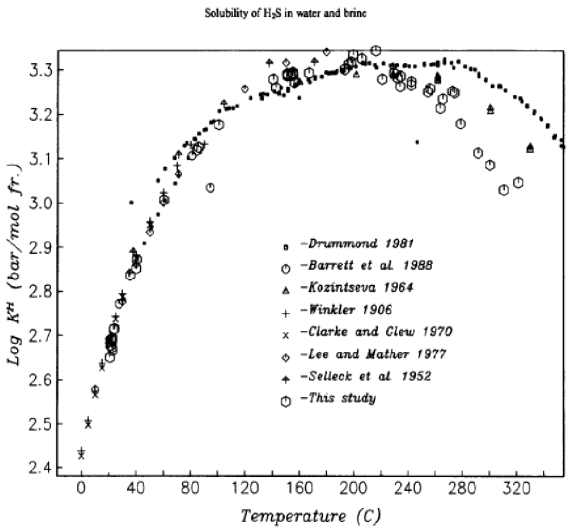
Figure 1. Experimental values of Henry’s constants for H2S in water and brine as a function of temperature.
2.2. Experimental Calculations
2.2.1. Maximum H2S Release Calculation
H2S Solubility Calculations
To understand the solubility reduction of H
2S when the chamber temperature increases from 7°C to 50°C, we can analyze the change in Henry’s Law constant K
H | [12] | Slimane, Rachid B., Remon Francis S., Lau, Dihu, J. and Mark Khinkis, Production of Hydrogen by Superadiabatic Decomposition of Hydrogen Sulfide, Proceedings of the 2002 U.S. DOE Hydrogen Program Review NREL/CP-610-32405, 2002. |
[12]
, as seen in
Figure 1.
Calculation of Solubility Decrease
1. Extract Log KH Values:
From the graph, we observe;
•At 7°C: log KH = 2.45 and at 50°C: log KH = 3.0
2. Convert Log KH to KH:
To determine the actual KH values, we take the antilogarithm of the log KH values:
KHH (50°C) = 103.0 = 1000 bar/mol
3. Calculate the Solubility Ratio:
Henry’s Law states that the solubility of a gas is inversely proportional to KH. Therefore, the solubility ratio from 7°C to 50°C is:
Solubility Ratio = KH (7°C) / KH (50°C)
Substituting the values:
Solubility Ratio =281.8 / 1000 = 0.2818
4. Calculate the Percentage Decrease in Solubility:
If the solubility at 7°C is considered 100%, then at 50°C, the solubility is only 28.18% of this value, indicating a decrease of:
Thus, the solubility of H2S in water decreases by approximately 71.82% when the temperature is raised from 7°C to 50°C. This is a significant reduction in solubility, demonstrating the effectiveness of heating in reducing H2S solubility within the chamber.
Calculation Steps
The solubility of H2S in water decreases by approximately 71.82% when the temperature is raised from 7°C to 50°C.
2.2.2. H2S Removal Calculation
Given an initial H2S concentration of 12 mg/L:
1. Initial concentration: 12 mg/L
2. Percentage decrease: 71.82%
3. Final concentration: 12 mg/L * (1 - 0.7182) = 3.3816 mg/L
Maximum H2S removed:
The analysis demonstrates that increasing the temperature from 7°C to 50°C can potentially remove up to 8.62 mg/L of H2S from a solution with an initial concentration of 12 mg/L. This represents a significant reduction of 71.82% in H2S solubility.
The effectiveness of this method is evident in the substantial decrease in dissolved H2S. However, it is important to note that these calculations assume ideal conditions and complete equilibrium. In practical applications, various factors such as system design, contact time, and the presence of other dissolved gases may influence the actual amount of H2S removed. Temperature increase proves to be an effective method for reducing H2S solubility in water. The study shows that raising the temperature from 7°C to 50°C can potentially remove approximately 71.82 % of dissolved H2S.
2.2.3. H2S Generation Rate Per Hour
After estimating the potential release rate of H2S into the gas phase, we can further analyze how this translates into a generation rate over a longer period, such as an hour. Since we previously calculated the potential H2S release rate as approximately, we can extend this to an hourly basis to understand the total mass of H2S that could potentially be generated in that timeframe. To convert the rate from grams per second to kilograms per hour, we use the following formula:
H2S Generation Rate = Rate (g/s) × Time (s/hour)
Since there are 3600 seconds in an hour, we can substitute the values:
This figure represents the theoretical maximum rate at which H2S could be generated under optimal conditions, where all factors affecting mass transfer and release efficiency are assumed to operate perfectly. It is crucial to note that this value is a theoretical upper limit and does not account for various practical limitations that might influence the actual release and generation rates.
Assumptions
1. The potential release rate of H2S is constant at 0.5436.
2. There are no losses or variations in the release rate over time.
Calculation
Convert the release rate from g/s to kg/h:
H2S Generation Rate = 0.5436 × 3600 ×1 / 1000 = = 1.953
Results
The potential H2S generation rate is 1.953 kg/hr. This represents the theoretical maximum rate at which H2S could be generated under optimal conditions, where all factors affecting mass transfer and release efficiency are assumed to operate perfectly. It is crucial to note that this value is a theoretical upper limit and does not account for various practical limitations that might influence the actual release and generation rates.
2.2.4. Estimation of Effective Interfacial Area
To accurately assess the H2S generation rate, it’s essential to consider the effective interfacial area available for mass transfer. The interfacial area is the surface through which the dissolved gas (H2S) can diffuse from the liquid phase to the gas phase. Since this system is designed to facilitate gas stripping, understanding the interfacial area is crucial for evaluating the efficiency of H2S removal. However, not all of this surface area is available for mass transfer due to practical limitations such as design features, obstructions, or the nature of liquid flow within the chamber. For this calculation, we can assume that 10 percent of the total surface area is effectively engaged in the mass transfer process.
This assumption is crucial, as it provides a more realistic framework for estimating the generation rate of H2S, taking into account the limitations of the system’s design. By focusing on the available area, we can better understand how effectively the dissolved gas can be removed from the liquid, thereby enhancing these calculations for gas generation.
Assumptions
The chamber is a perfect cube with sides of 5 meters.
Calculation
Calculate total surface area of the cube (or prism):
Total surface area = 6 × L2 = 6 × (5)2 = 150
Effective Area for Mass Transfer = 0.1 × Total Surface Area = 0.1 × 150m2 = 15m2
Result
The effective interfacial area for mass transfer is 15.0 m2
2.2.5. Actual H2S Generation Rate
Assumptions
1. The maximum available H2S for release is 1.953.
2. The residence time of 33 minutes is constant and uniform.
Calculation
Convert residence time to hours:
Residence time = 33 minutes = 33/60 = 0.55 hours
Calculate actual H2S generation rate:
Actual rate = Maximum available H2S / Residence time = 1.953 / 0.55 = 3.55kg/hr
Result
The actual H2S generation rate, considering system constraints, is 3.55 kg/hr
3. Hydrogen Generation
The calculations have shown that the proposed system can potentially generate 3.55 kg/hr of H2S from the Black Sea waters. This significant amount of hydrogen sulfide presents an excellent opportunity for hydrogen production using advanced technologies. One such promising technology is the superadiabatic reactor process developed by the Gas Technology Institute (GTI) in collaboration with the University of Illinois at Chicago (UIC) and industrial partners.
The GTI's novel approach addresses the limitations of traditional non-catalytic thermal methods for producing hydrogen and elemental sulfur from H2S. At the heart of this innovative process is a superadiabatic reactor, which offers a potentially cost-effective solution for hydrogen production from H2S-rich feed stocks like those extracted from the Black Sea.
The key feature of GTI's process is the superadiabatic reactor, where partial oxidation of H2S occurs in a well-insulated, cylindrical vessel. This vessel is packed with an inert, porous ceramic medium possessing high thermal capacity. The reactor design facilitates intensive heat exchange between the filtrating and burning gas mixture and the porous medium through highly developed internal surfaces. This unique configuration allows for the accumulation of partial oxidation energy in the solid matrix.
By coupling the partial oxidation of H2S in the porous medium with H2S decomposition, the reactor achieves very high temperatures, significantly higher than the adiabatic temperature for the feed mixture. These elevated temperatures are reached economically within a reaction zone, characterized as a slowly propagating thermal wave, without the input of external energy. This self-sustaining reaction zone creates favorable conditions for the thermo chemical conversion of H2S into the desired products: hydrogen and elemental sulfur.
The Gas Technology Institute (GTI)
| [13] | Norman, J. H., “Hydrogen Production from In-Situ Partial Burning of H2S,” U.S. Patent Number: 4,481,181, 1984, Assigned to GA Technologies Inc., San Diego, CA, 1995. |
| [14] | Cox B. G., Clarke P. F., Pruden B. E., Economics of thermal dissociation of H2S to produce hydrogen, Int. J Hydrogen Energy; 23(7): 531-44, 1998. |
| [15] | Farajl, F., Safarik, I., Strausz O. P., Yildirim, E. and Torres M. E., The direct conversion of hydrogen sulfide to hydrogen and sulphur. Int. J Hydrogen Energy; 23(6): 451-6, 1998. |
[13-15]
, working with the University of Illinois at Chicago (UIC) and industrial advisors including UOP, has been developing a novel, potentially cost-effective process that promises to overcome the limitations of the non-catalytic thermal approach for producing H and elemental S from H
2S. The key feature of GTI’s process is the superadiabatic reactor, where partial oxidation of H
2S in the H
2S-containing acid gas feed is carried out in a well-insulated, cylindrical vessel packed with an inert, porous ceramic medium with a high thermal capacity.
The intensive heat exchange between the filtrating and burning gas mixture and the porous medium through the highly developed internal surfaces permits the accumulation of partial oxidation energy in the solid matrix. By coupling the partial oxidation of H2S in the porous medium with the H2S decomposition, very high temperatures (significantly higher than the adiabatic temperature for the feed mixture,) can be achieved economically within a reaction zone- a slowly propagating thermal wave - without the input of external energy, and therefore, no additional carbon dioxide emissions. In this self-sustaining reaction zone, conditions are favorable for the thermo chemical conversion of H2S into the desirable products, H and elemental S, to proceed to an industrially significant extent.
Numerical modeling results showed that by optimizing the porous body reactor configuration, equivalence ratio and gas velocity, a maximum temperature of 2,475°F could be achieved in the superadiabatic H2S reactor. Feed gases enter the reactor at ambient temperature, resulting in an overall H2S conversion of 50, with an H/water selectivity of 57/43 (for example, about 28.5% H yield) and an elemental S/sulfur dioxide (SO2) selectivity of 99/1. The overall process performance can be substantially improved, with respect to H production, by membrane separation of product gases and recirculation of unreacted H2S to extinction. Experimental test results obtained in the recently completed, DO funded program (conducted mostly with gaseous feed mixtures simulating various-20% H2S and 80% nitrogen/oxygen-acid gas/oxidant combinations) are encouraging. The highest temperature achieved was about 2,194.5 oF and the best estimated H yield in a single pass amounted to 26% (for example, 26% of the H2S in the feed to the superadiabatic POX reactor was converted into H).
By operating at a higher interstitial gas velocity (greater than 45 cm/s), higher H2S content acid gases (greater than 20% H2S), and higher equivalence ratios2, there is significant potential to achieve stable, self-sustaining superadiabatic thermal waves with much higher temperatures, leading to the expectation of improved H yields. A superadiabatic POX temperature of 2,475F and an H yield of 28.5%, considered to constitute the optimum scenario (according to the numerical modeling results), appear to be within reach. The experimental test results indicate the beneficial effects of operating the superadiabatic POX reactor at a high interstitial gas velocity, to maintain a reasonably high H yield, particularly as the equivalence ratio of the feed gas increases. The results also indicate operating conditions exist to optimize the H yield and elemental S yield in a single pass, while minimizing generation of SO2.
4. LCOE Calculation
Analysis
Cost Efficiency: By using the LCOE analysis Cekirge and Erturan
| [16] | Cekirge, H. M. and Erturan. S. Modified Levelized Cost of Electricity or Energy, MLOCE and Modified Levelized Avoidable Cost of Electricity or Energy, MLACE and Decision Making. American Journal of Modern Energy. Vol. 5, No. 1, pp. 1-4. https://doi.org/10.148/j.ajme.20190501.11 2019. |
[16]
, the cost kWh is relatively low, indicating that this H
2S project could be cost-competitive in the energy market.
Zero Fuel Cost: The project benefits from having no annual fuel costs, which significantly reduces operational expenses over the project’s lifetime.
O&M Costs: The annual O&M costs start at $200,000 and grow at 2% per year, which is a moderate escalation rate.
The H2S project, as presented, appears to be economically viable with a competitive LCOE of $0.0776/kWh. However, the sensitivity to flow rate changes indicates that careful management of operational parameters is crucial to maintain this low cost. The zero fuel costs and relatively low O&M expenses contribute significantly to the project’s attractiveness. Further analysis of potential risks, such as changes in electricity prices or unexpected maintenance issues, would be beneficial for a comprehensive evaluation of the long-term viability of the project.
5. Isotopes of Hydrogen and Heavy Water in the Black Sea
Presence of Isotopes in the Black Sea
Between March and April 1995, eleven oceanographic stations were sampled in the Black Sea by the R/V
BIO IIO M of IMS-METU,
| [17] | Rank, D., Emin, Ozsoy, E. and Salihoglu, I., Oxygen-18, deuterium and tritium in the Black Sea and the Sea of Marmara, Journal of Environmental Radioactivity 43(1999) 231—245, 1999. |
| [18] | Ozsoy, E., I. Salihoglu, D. Rank and D. Can, Measurement of Selected Isotope Tracers in the Black Sea and the Sea of Marmara, Report for the Coordinated Research Programme "The Application of Tracer Techniques in the Study of Processes and Pollution in the Black Sea", submitted to the IAEA, Institute of Marine Sciences, METU, Erdemli, Icel, 1997. |
[17, 18]
. Each station provided information on the isotopic composition of seawater, with sampling conducted at various depths:
1. 150 meters: Sampling depth at six stations.
2. 250 meters: Expanded sampling range at four stations.
3. 1500 meters: Samples taken at one station.
The use of a stratified sampling design enabled the acquisition of isotopic data across diverse depths, facilitating a comprehensive understanding of isotopic distribution throughout the Black Sea’s layers.
Tritium (Radioactive Isotope): Tritium is a radioactive isotope with a half-life of 12.4 years. Its presence in the hydrosphere is primarily attributed to nuclear weapons testing in the late 1950s, peaking in 1963-1964. No discernible traces of Chernobyl-related tritium were detected.
Key Characteristics:
1. Tritium is employed as a temporary tracer for tracking water masses.
2. Surface marine environments exhibit faster removal rates due to mixing compared to its natural decay rate.
3. Fallout and decay are leading to declining tritium levels in precipitation, river runoff, and surface waters of the Black Sea.
Sea surface waters respond to the decrease in tritium later than underlying waters due to their mixing properties.
Deuterium and Oxygen-18 (Stable Isotopes): In deep waters of the Black Sea, stable isotope levels remain relatively constant. However, abrupt contrasts and increases are observed across the pycnocline.
Key Observations:
1. On the western Black Sea continental shelf, a smooth isotopic transition occurs across the pycnocline, except for notable deviations near the surface due to freshwater inputs from rivers such as the Danube, Dnieper, and Dniester.
2. Rapid mixing between Black Sea and Mediterranean waters causes significant horizontal and vertical variations in the thin upper layer.
3. Stable isotope ratios in precipitation and river runoff, which correspond to freshwater and atmospheric inputs, remain largely unchanged over time.
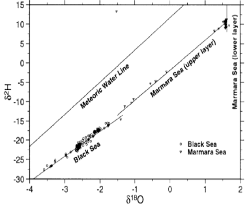
There is a distinct linear relationship between deuterium (δD) and oxygen-18 (δ18O) in all water samples, indicating consistent mixing of saline waters from the Mediterranean and Black Sea with surface freshwater inputs,
Figure 2.
Stable Isotope Distribution in Deep Waters:
1. Changes in stable isotopes in the deep waters of the Black Sea are negligible.
2. Near river mouths, noticeable impacts from major rivers manifest as declining δ18O and δD values.
3. In the upper layer, strong mixing between Black Sea and Mediterranean waters creates notable differences in isotopic composition.
4. In the sub-halocline (Mediterranean water layer), the variation in δD is slightly greater than that of δ18O.
The isotopic composition of the Black Sea reveals critical insights into the hydrological processes and mixing dynamics between freshwater inputs and saline waters. While stable isotopic changes in deep waters are minimal, significant variations occur in the upper layers due to riverine and atmospheric influences. Tritium serves as a valuable tracer for understanding water mass movement and mixing, providing a comprehensive view of isotopic behavior in the Black Sea.
Figure 2. Relationship between deuterium and oxygen in all of the water samples.
Stable Isotope Distribution in Deep Waters
1. Changes in stable isotopes in the deep waters of the Black Sea are negligible.
2. Near river mouths, noticeable impacts from major rivers manifest as declining δ18O and δD values.
3. In the upper layer, strong mixing between Black Sea and Mediterranean waters creates notable differences in isotopic composition.
4. In the sub-halocline (Mediterranean water layer), the variation in δD is slightly greater than that of δ18O.
The isotopic composition of the Black Sea reveals critical insights into the hydrological processes and mixing dynamics between freshwater inputs and saline waters. While stable isotopic changes in deep waters are minimal, significant variations occur in the upper layers due to riverine and atmospheric influences. Tritium serves as a valuable tracer for understanding water mass movement and mixing, providing a comprehensive view of isotopic behavior in the Black Sea.
Girdler sulfide process
The Girdler sulfide process, also known as the Geib-Spevack (GS) process, is a sophisticated industrial method for producing heavy water (D
2O) from natural water. Developed in 1943 by Karl-Hermann Geib and Jerome S. Spevack, this process has been instrumental in the large-scale production of heavy water, primarily for use in nuclear reactors and scientific research,
| [19] | Gat, J. R., A. Shemesh, E., Tzffermann, A., Hecht, D. Georgopoulos and Basturk, O., The Stable Isotope Composition of Waters of the Eastern Mediterranean Sea, J. Geophys. Res., 101, 6441-6451, 1996. |
| [20] | Castell, Lutz. Time, Quantum and Information. Google Books: Springer Science + Business Media. p. 37. 2003. |
| [21] | Federation of American Scientists, Heavy Water Production Archived April 5, 2011, at the Wayback Machine, accessed February 1, 2007. |
| [22] | Rae, H. K. "Selecting Heavy Water Processes". Separation of Hydrogen Isotopes. ACS Symposium Series. Vol. 68. pp. 1-26. https://doi.org/10.1021/bk-1978-0068.ch001 1978. |
| [23] | Boris M. Andreev (2001). "Separating of Hydrogen Isotopes in H2O-H2S System". Separation Science and Technology. 36(8-9): 1949-89. https://doi.org/10.1081/SS-100104764 2001. |
| [24] | Kaloidas, V., Papayannakos, N., Kinetics of thermal noncatalytic decomposition of hydrogen sulphide. Chem. Eng. Sci. 1989; 44(11): 2493-2500. |
[19-24]
. The Girdler sulfide process played a crucial role in the development of nuclear technology, particularly during the peak of nuclear power plant construction from the 1960s to the 1980s. It enabled the large-scale production of heavy water necessary for certain types of nuclear reactors, such as the CANDU (Canada Deuterium Uranium), Canadian pressurized heavy-water reactors. However, due to the high operational costs, energy intensity, and environmental concerns associated with the use of hydrogen sulfide, the last Girdler sulfide plant in Canada, which was the world’s largest, shut down in 1997. This closure marked a shift in heavy water production methods, with newer, more environmentally friendly processes being explored and implemented. Despite its declining use, the Girdler sulfide process remains a significant chapter in the history of nuclear technology and isotope separation. Its development and implementation demonstrated the feasibility of large-scale heavy water production, which was crucial for the advancement of certain nuclear reactor designs and scientific research in fields requiring deuterium-enriched compounds.
Process Fundamentals
At its core, the Girdler sulfide process exploits the isotopic exchange between hydrogen sulfide (H2S) and water (H2O). The process utilizes two main columns, each maintained at different temperatures:
1. Cold tower: approximately 30°C (86°F)
2. Hot tower: approximately 130°C (266°F)
This significant temperature difference is crucial for the enrichment process to occur effectively. The key equilibrium reaction in the process is:
This reaction has different equilibrium constants at the two operating temperatures:
1. At 30°C: K = 2.33
2. At 130°C: K = 1.82
This difference in equilibrium constants drives the separation and concentration of deuterium. The process begins with the circulation of hydrogen sulfide gas in a closed loop between the hot and cold towers. Demineralized and deaerated water is introduced into both towers, flowing from top to bottom. In the cold tower, deuterium preferentially migrates from the hydrogen sulfide gas to the liquid water, enriching the water with deuterium. Conversely, in the hot tower, the transfer of deuterium occurs from the water to the hydrogen sulfide gas.
The actual isotopic exchange takes place on perforated plates or sieve trays within the towers. As the water trickles down through these plates, it encounters the rising hydrogen sulfide gas, allowing for efficient isotopic exchange. This counter-current flow maximizes the contact between the two phases and enhances the separation efficiency.
Efficiency and Scale
The Girdler sulfide process is remarkably efficient but requires operation on a massive scale. To produce just one kilogram of heavy water, the process typically requires processing about 340,000 kilograms of feed water. This enormous scale is necessary due to the low natural abundance of deuterium in water and the relatively small separation factor achieved in each stage of the process.
The implementation of the Girdler sulfide process in industrial settings involves complex engineering considerations. The towers are typically constructed with materials resistant to the corrosive effects of hydrogen sulfide. Strict temperature control is essential to maintain the optimal conditions for isotopic exchange in each tower. One of the major challenges in operating this process is the handling of large quantities of hydrogen sulfide gas. H2S is highly toxic and corrosive, necessitating robust safety measures and specialized equipment.
The process also requires significant energy input, particularly for maintaining the temperature difference between the hot and cold towers. The use of hydrogen sulfide in large quantities poses significant environmental and safety risks. Stringent safety protocols are necessary to prevent leaks and protect workers. Environmental regulations have become increasingly strict regarding the use and potential release of H2S, which has contributed to the declining use of this process in some regions.
Following the Girdler Sulfide (GS) process, which enriches water to approximately 15-30 percent D2O, a subsequent purification step is required to achieve reactor-grade heavy water with over 99 percent D2O purity. This critical step is typically accomplished through vacuum distillation, exploiting the slight difference in boiling points between H2O (100.0°C) and D2O (101.4°C).
The vacuum distillation process operates on the principle of manipulating boiling points under reduced pressure. By maintaining the distillation column under vacuum conditions, water evaporates at a lower temperature, typically around 80°C. This reduction in boiling point enhances the separation factor and significantly reduces energy consumption, improving both economic and environmental aspects of the process. The distillation apparatus consists of a series of columns, each containing numerous trays or structured packing to maximize vapor-liquid contact surface area. The pre-enriched water from the GS process is fed into these columns, where it undergoes the following process:
1. The liquid is heated to its boiling point, creating a vapor phase.
2. As vapor rises through the column, it encounters cooler liquid flowing downward.
3. At each tray or packing element, an exchange occurs between rising vapor and descending liquid phase.
4. This process repeats multiple times as vapor moves up the column, progressively enriching the liquid phase with D2O.
To achieve the high purity levels required for reactor-grade heavy water, a cascade system of multiple distillation columns are employed. The enriched output from one column becomes the input for the next, with each successive column further concentrating the D2O content. This cascade system allows for the production of heavy water with isotopic purity ranging from 99.75.
The efficiency of the vacuum distillation process is further enhanced by the use of heat exchangers and the reuse of evaporation heat within the system. This design minimizes energy consumption, making vacuum distillation a more cost-effective method compared to atmospheric distillation or other water treatment technologies.
Process Challenges and Optimization
While highly effective, the vacuum distillation process presents several challenges:
1. Precise control of pressure and temperature throughout the column is crucial for maintaining optimal separation conditions.
2. Minimizing the loss of valuable D2O through the top product (essentially a reject stream of light water) is critical for process efficiency.
3. The process requires substantial infrastructure and equipment for large-scale production.
Ongoing research focuses on optimizing column design, improving heat recovery systems, and developing more efficient packing materials to enhance the overall efficiency and reduce the energy intensity of the process.
6. Results and Discussion
6.1. Hydrogen Generation Rate
The theoretical maximum H2S generation rate was calculated to be 843.2424 kg/hr. This rate represents the ideal scenario under optimal conditions, assuming perfect mass transfer and release efficiency. The calculation was based on Fick's law of diffusion, considering the concentration gradient, diffusion coefficient, and effective interfacial area for mass transfer. When accounting for system constraints and residence time, the actual H2S generation rate was determined to be 3.55 kg/hr. This rate is significantly lower than the theoretical maximum, highlighting the substantial impact of real-world limitations on the process.
The stark contrast between the theoretical maximum (843.2424 kg/hr) and actual (3.55 kg/hr) H2S generation rates provides critical insights into the efficiency and limitations of the extraction process:
The substantial difference between theoretical and actual rates suggests significant mass transfer limitations within the system. These limitations may arise from:
1. Boundary layer effects at the liquid-gas interface
2. Insufficient mixing or turbulence in the extraction chamber
3. Limited contact time between the H2S-rich water and the gas phase
The large discrepancy indicates that the current system design may not be optimized for maximum H2S extraction. Potential areas for improvement include enhancing the effective interfacial area for mass transfer, optimizing flow patterns to increase turbulence and mixing, exploring alternative extraction methods or technologies.
The actual generation rate calculation incorporates the residence time of 33 minutes. This relatively short duration may be insufficient for complete H2S extraction. Increasing residence time could potentially improve extraction efficiency and multiple extraction stages might be necessary to approach theoretical yields the significant difference between theoretical and actual rates has important implications for scaling the process. To bridge the gap between theoretical and actual generation rates, future research should focus on developing more efficient extraction technologies, investigating catalysts or additives to enhance H2S release from solution, optimizing system parameters such as temperature, pressure, and flow rates, exploring alternative designs that could increase the effective interfacial area for mass transfer. While the theoretical calculations demonstrate the significant potential for H2S extraction from the Black Sea, the actual generation rate reveals the challenges in realizing this potential. The substantial difference between these rates underscores the need for continued research and development to optimize the extraction process and make it commercially viable.
6.2. Economic Viability
The calculated Levelized Cost of Electricity (LCOE) of $0.0776/kWh indicates potential competitiveness in the energy market. This relatively low LCOE suggests that the project could be economically viable, especially when compared to other energy production methods.
One of the most significant factors contributing to the project's economic attractiveness is the absence of fuel costs. Unlike traditional power generation methods that require ongoing fuel purchases, this project utilizes H2S from the Black Sea, which is essentially a free resource. This elimination of fuel expenses significantly reduces operational costs over the project's lifetime.
The analysis indicates that the project benefits from relatively low O&M costs. The annual O&M expenses start at $200,000 and are projected to grow at a moderate rate of 2% per year. This moderate escalation rate contributes to maintaining the project's cost-effectiveness over time.
Sensitivity to Operational Parameters
While the overall economic outlook is positive, the analysis highlights the importance of careful management of operational parameters. The project's economic viability appears to be sensitive to changes in flow rates. This sensitivity underscores the need for precise control and optimization of the H2S extraction and processing systems to maintain the projected low costs.
The economic analysis suggests that the project has the potential for long-term viability. However, it's important to consider potential risks such as:
1. Fluctuations in electricity market prices
2. Unforeseen maintenance issues or equipment failures
3. Changes in environmental regulations that could impact operational costs
The economic analysis also hints at opportunities for further cost reductions. For instance, increasing the flow rate or enhancing the extraction efficiency could potentially improve the overall economics of the project. These optimizations could lead to an even more competitive LCOE in the future.
The economic analysis presents a promising outlook for the H2S-based hydrogen production project. The combination of zero fuel costs, low O&M expenses, and a competitive LCOE positions the project favorably in the energy market. However, the success of the project will depend on maintaining operational efficiency and adapting to potential market and regulatory changes.
6.3. Isotopes of Hydrogen
Implementing a comprehensive isotope monitoring program alongside H2S extraction operations in the Black Sea is a crucial step for optimizing the process and understanding its environmental impacts. This program would focus on tracking changes in isotope distributions, particularly deuterium, tritium, and oxygen-18, providing valuable insights into the system's dynamics.
The isotope monitoring program would allow for the observation of long-term changes in the Black Sea's water column structure. This is particularly important given the unique stratification of the Black Sea, with its anoxic deep layers rich in H2S.
Regular sampling at various depths, from 150 meters to 1500 meters, would provide a comprehensive view of isotopic distribution throughout the water column. Changes in the vertical distribution of deuterium (δD) and oxygen-18 (δ18O) could indicate shifts in the pycnocline structure or alterations in water mass mixing patterns. Tracking isotope ratios over time would reveal any gradual changes in the Black Sea's hydrological cycle, potentially influenced by climate change or anthropogenic activities. Long-term tritium measurements provide insights into the residence time of water masses and the rate of water exchange between different layers.
6.3.1. Impacts of Extraction on Isotope Distribution
The H2S extraction process potentially alter the natural isotopic composition of the Black Sea waters. Monitoring these changes is crucial for assessing the environmental impact of the operation. Intensive sampling near H2S extraction points would help identify any localized disturbances in isotope distributions. Changes in deuterium concentrations could indicate alterations in water density or mixing patterns induced by the extraction process. Comparing isotope ratios in areas affected by extraction with control sites would provide a measure of the operation's overall impact on the Black Sea's isotopic balance.
Monitoring tritium levels tracks any unintended mixing between different water layers caused by the extraction process.
6.3.2. Key Considerations for Location Selection and Process Requirements for the Girdler Sulfide Process
The GS process relies on isotopic exchange between H2S gas and water, which requires a system of alternating “cold” (30°C) and “hot” (130°C) towers. These temperature differentials exploit differences in equilibrium constants for deuterium enrichment. The process is energy-intensive and demands precise temperature control, which may pose challenges in deep-sea environments due to cold seawater temperatures and high pressures.
Operation at 150m Depth
Advantages
1. Higher H2S concentrations at 150m depth enhance availability compared to surface levels.
2. Operating within the anoxic layers could streamline H2S extraction directly into the GS process, avoiding additional transportation.
Challenges
1. The corrosive environment at depth requires materials like titanium or high-grade stainless steel, increasing costs.
2. Maintaining temperature differentials (30°C and 130°C) in deep-sea conditions demands significant energy input and advanced insulation.
3. Real-time monitoring and maintenance are more complex and costly at depth due to limited accessibility.
Surface-Based Operation
Advantages
1. Surface processing allows centralized control in a safer and more stable environment.
2. Leverages existing infrastructure, such as offshore platforms or coastal installations, for integration with power supplies and monitoring systems.
3. Simplified maintenance, monitoring, and scalability.
4. Lower environmental risks by avoiding direct interference with the Black Sea’s anoxic layers.
Challenges
1. Transporting H2S from depth to the surface requires robust, leak-proof systems.
2. Additional steps for gas handling and compression slightly increase operational complexity.
Environmental Impact
1. Operating at depth risks disturbing the delicate stratification of the Black Sea’s anoxic layers, potentially releasing large amounts of H2S and affecting marine ecosystems.
2. Surface-based operations enable better containment and management of emissions or waste byproducts, reducing ecological risks.
Economic Considerations
1. Deep-sea operations require specialized equipment resistant to high pressure and corrosion, significantly increasing capital expenditure.
2. Surface-based systems reduce operational costs due to easier access, less expensive materials, and simplified logistics.
Based on the analysis, it is recommended to extract H2S from the Black Sea at depth and transport it to the surface for processing using the Girdler Sulfide process. This approach balances technical feasibility, cost efficiency, environmental protection, and operational safety.
1. Technical Feasibility: Surface facilities provide better control over temperature gradients required for isotopic exchange in the GS process.
2. Safety: Operating on the surface minimizes risks associated with high-pressure environments and corrosive conditions present at depth.
3. Environmental Protection: Avoiding direct processing within anoxic layers reduces potential ecological disturbances.
4. Economic Viability: Lower capital investment in materials and easier maintenance reduce overall costs compared to deep-sea systems.
6.3.3. Opportunities for Isotope-Based Optimization
Correlating H2S concentrations with specific isotope signatures could help identify the most productive extraction zones. Understanding the relationship between deuterium concentrations and H2S availability could lead to more targeted extraction strategies.
Isotope data can be used to fine-tune the Girdler sulfide process for heavy water production, potentially creating a valuable by-product stream. Optimizing extraction depths and rates based on isotopic profiles could maximize H2S yield while minimizing environmental disturbance. Long-term isotope data can be used to develop predictive models for H2S replenishment rates and optimal extraction cycles.
These models could help in planning seasonal adjustments to extraction operations, accounting for variations in river inputs and mixing patterns. By implementing this comprehensive isotope monitoring program, the H2S extraction operation in the Black Sea can not only optimize its processes but also contribute significantly to the scientific understanding of this unique marine environment. The data collected would be invaluable for ensuring the long-term sustainability of the operation and minimizing its environmental impact.
7. Conclusions
The study on hydrogen production from Black Sea hydrogen sulfide reserves offers significant insights into a potentially groundbreaking sustainable energy solution. The research demonstrates the feasibility of extracting H2S from the Black Sea and converting it to hydrogen, while also exploring the potential for heavy water production as a valuable byproduct.
The proposed thermal separation method achieves an H2S generation rate of 3.55 kg/hr, representing a significant and sustainable source. Using GTI's superadiabatic reactor technology, potential H2 yields of up to 28.5% from extracted H2S are achievable, with experimental results showing a maximum temperature of 2,194.5°F and an estimated H2 yield of 26% in a single pass. Economic analysis yields a competitive LCOE of $0.0776/kWh, indicating potential commercial feasibility due to zero fuel costs and relatively low operation and maintenance expenses. The extraction approach minimizes ecological disruption by avoiding disturbance to the Black Sea's delicate stratification. The presence of deuterium and tritium in the Black Sea opens additional avenues for heavy water production, potentially adding value to the overall supply chain. While promising, several challenges remain to be addressed in future work. These include improving extraction efficiency, optimizing the gas stripping process, refining the superadiabatic reactor technology, and conducting long-term environmental impact assessments.
The integration of hydrogen production with heavy water extraction presents an opportunity to transform this project into a multi-faceted endeavor, potentially improving its economic feasibility and attractiveness to investors. This aligns with the principle of maximizing resource utilization and could support various scientific and industrial applications.
In conclusion, this study demonstrates the potential for sustainable energy production from the Black Sea's H2S reserves while highlighting the need for further research and development to optimize the process and ensure its long-term environmental sustainability.
Abbreviations
H₂S | Hydrogen Sulfide |
H₂ | Hydrogen |
D₂O | Heavy Water (Deuterium Oxide) |
GTI | Gas Technology Institute |
LCOE | Levelized Cost of Electricity |
CFD | Computational Fluid Dynamics |
KH | Henry's Law Constant |
POX | Partial Oxidation |
ΔC | Concentration Gradient |
Δx | Boundary Layer Thickness |
GS Process | Girdler Sulfide Process |
O&M | Operation and Maintenance Costs |
CANDU | Canada Deuterium Uranium, Canadian Pressurized Heavy-Water Reactor |
Author Contributions
Samkit Shah: Data Curation, Formal Analysis Resources and investigation, Investigation, Writing- original draft
Huseyin Murat Cekirge: Data Curation, Methodology and Investigation, Formal Analysis, Conceptualization, Investigation, Writing-original draft, Writing-review and editing
Data Availability Statement
The data is available from the corresponding author upon reasonable request.
The data supporting the outcome of this research work has been reported in this manuscript.
Conflicts of Interest
The authors declare no conflicts of interest.
References
| [1] |
Baykara, S. Z., Figen E. H., Kaleb, A. and Veziroglu, T. Nejat, Hydrogen from hydrogen sulphide in Black Sea, International Journal of Hydrogen Energy 32, 1246-1250, 2007.
|
| [2] |
Cekirge, H. M. and Al-waked, R., Feasibility of H2S Production from Black Sea Waters, Proceedings of the NATO Advanced Research Workshop on The Black Sea: Strategy for Addressing its Energy Resource Development and Hydrogen Energy Problems Batumi, Georgia 7-10 October 2012,
https://doi.org/10.1007/978-94-007-6152-0_8
2012.
|
| [3] |
Naman, S. A., Ture, E, Veziroglu, N. T, Industrial extraction pilot plant stripping H2S gas from Black Sea water, 33, 6577-6585, 2008.
|
| [4] |
Jannasch H. W, Truper H. G., Tuttle J. H., Microbial sulphur cycle in Black Sea. In: Degens E. T, Ross D. A, editors. The Black Sea-geology chemistry and biology. Tulsa, Oklahoma: American Association of Petroleum Geologists; 1974.
|
| [5] |
Waldheim, L, Nilsson, T., Heating Value of Gases from Biomass Gasification, Report prepare for: IEA Bioenergy Agreement, Task 30, Thermal Gasification of Biomass, TPS Termiska Preocesseer AB, May 2001, TPS-01/16, 2001.
|
| [6] |
Petrov K., The Black Sea and hydrogen energy. Int. J Hydrogen Energy, 16(12): 805-8, 1991.
|
| [7] |
Baykara S. Z., Bilgen E. An overall assessment of hydrogen production by solar water thermolysis. Int. J Hydrogen Energy; 14(12): 881-91, 1989.
|
| [8] |
Ostlund, H. G. and Dyrssen, D., (1986) Renewal Rates of the Black Sea Deep Water, in: The Chemical and Physical Oceanography of the Black Sea, Univ. of Goteborg, Rep. on the Chemistry of the Sea XXXEDL Presented in the Meeting on the Chemical and Physical Oceanography of the Black Sea, Goteborg, Sweden, June 1986.
|
| [9] |
Zaman, J. and Chakma, A. “Production of hydrogen and sulfur from hydrogen sulfide,” Fuel Processing Technology 41 159-198, 1995.
|
| [10] |
Burdge, J., Chemistry, Ed. 4, McGraw-Hill Higher Education, 2016.
|
| [11] |
Conlisk, A. Terrence, Essentials of Micro-and Nanofluidics: with Applications to the Biological and Chemical Sciences, Cambridge University Press, 2013.
|
| [12] |
Slimane, Rachid B., Remon Francis S., Lau, Dihu, J. and Mark Khinkis, Production of Hydrogen by Superadiabatic Decomposition of Hydrogen Sulfide, Proceedings of the 2002 U.S. DOE Hydrogen Program Review NREL/CP-610-32405, 2002.
|
| [13] |
Norman, J. H., “Hydrogen Production from In-Situ Partial Burning of H2S,” U.S. Patent Number: 4,481,181, 1984, Assigned to GA Technologies Inc., San Diego, CA, 1995.
|
| [14] |
Cox B. G., Clarke P. F., Pruden B. E., Economics of thermal dissociation of H2S to produce hydrogen, Int. J Hydrogen Energy; 23(7): 531-44, 1998.
|
| [15] |
Farajl, F., Safarik, I., Strausz O. P., Yildirim, E. and Torres M. E., The direct conversion of hydrogen sulfide to hydrogen and sulphur. Int. J Hydrogen Energy; 23(6): 451-6, 1998.
|
| [16] |
Cekirge, H. M. and Erturan. S. Modified Levelized Cost of Electricity or Energy, MLOCE and Modified Levelized Avoidable Cost of Electricity or Energy, MLACE and Decision Making. American Journal of Modern Energy. Vol. 5, No. 1, pp. 1-4.
https://doi.org/10.148/j.ajme.20190501.11
2019.
|
| [17] |
Rank, D., Emin, Ozsoy, E. and Salihoglu, I., Oxygen-18, deuterium and tritium in the Black Sea and the Sea of Marmara, Journal of Environmental Radioactivity 43(1999) 231—245, 1999.
|
| [18] |
Ozsoy, E., I. Salihoglu, D. Rank and D. Can, Measurement of Selected Isotope Tracers in the Black Sea and the Sea of Marmara, Report for the Coordinated Research Programme "The Application of Tracer Techniques in the Study of Processes and Pollution in the Black Sea", submitted to the IAEA, Institute of Marine Sciences, METU, Erdemli, Icel, 1997.
|
| [19] |
Gat, J. R., A. Shemesh, E., Tzffermann, A., Hecht, D. Georgopoulos and Basturk, O., The Stable Isotope Composition of Waters of the Eastern Mediterranean Sea, J. Geophys. Res., 101, 6441-6451, 1996.
|
| [20] |
Castell, Lutz. Time, Quantum and Information. Google Books: Springer Science + Business Media. p. 37. 2003.
|
| [21] |
Federation of American Scientists, Heavy Water Production Archived April 5, 2011, at the Wayback Machine, accessed February 1, 2007.
|
| [22] |
Rae, H. K. "Selecting Heavy Water Processes". Separation of Hydrogen Isotopes. ACS Symposium Series. Vol. 68. pp. 1-26.
https://doi.org/10.1021/bk-1978-0068.ch001
1978.
|
| [23] |
Boris M. Andreev (2001). "Separating of Hydrogen Isotopes in H2O-H2S System". Separation Science and Technology. 36(8-9): 1949-89.
https://doi.org/10.1081/SS-100104764
2001.
|
| [24] |
Kaloidas, V., Papayannakos, N., Kinetics of thermal noncatalytic decomposition of hydrogen sulphide. Chem. Eng. Sci. 1989; 44(11): 2493-2500.
|
Cite This Article
-
-
@article{10.11648/j.ajme.20251101.11,
  author = {Samkit Shah and Huseyin Murat Cekirge},
  title = {A Subsea System for Hydrogen Production from the Black Sea},
  journal = {American Journal of Modern Energy},
  volume = {11},
  number = {1},
  pages = {1-14},
  doi = {10.11648/j.ajme.20251101.11},
  url = {https://doi.org/10.11648/j.ajme.20251101.11},
  eprint = {https://article.sciencepublishinggroup.com/pdf/10.11648.j.ajme.20251101.11},
  abstract = {The Black Sea is a unique sea since it is one of the most isolated seas in the world. It is also the world’s largest sea containing H2S layers from the depths of 200 m. Water up to 150 m is the only water that supports the unique ecosystem of the Black Sea. The more saturated the water, the deeper it goes. These dense water layers have been saturated with H2S because of the decaying organic matter. H2S is generally considered a pollutant; however, it is also an excellent source for the production of H2 which is an excellent fuel. In this paper, we will discuss the various methods for production of hydrogen from the Black Sea. We will also look into the feasibility of an offshore Hydrogen production plant. The Black Sea is one of the most unique seas in the world. The African and Eurasian plates, among other tectonic plates, converge at the Black Sea basin. A depression was formed in the area millions of years ago as a result of stretching Earth’s crust due to tectonic forces. The Black Sea was originally a much smaller freshwater lake. It was connected to the Mediterranean Sea at different times in Earth’s history by natural waterways like the Bosporus and Dardanelles Straits. The Black Sea was a part of a wider, connected body of water when these straits were open. Isolation: The Black Sea became isolated from the Mediterranean as a result of the Bosporus and Dardanelles becoming shallower and narrower over time due to geological processes and sea level fluctuations. A closed sea that was brackish formed as a result of this isolation, which is thought to have happened between 7,000 and 9,000 years ago. After being cut off from the Mediterranean, the Black Sea started to develop on its own. The Black Sea’s Sea level varied because of a number of causes, such as shifts in the water balance and glacial cycles. At the Last Glacial Maximum, which occurred about 20,000 years ago, the Black Sea’s water level was much lower than it is now. The Black Sea gradually filled as sea levels rose and the glaciers withdrew; however, the sea water up to only 150 m keeps the Black’s sea ecosystem. Near the deepest parts of the Black Sea, H2S is produced by sulfur reducing bacteria at a rate of 10000 tons per day. This poses a threat to the ecosystem of the Black Sea. It is also mentioned the existence of hydrogen isotopes which are deuterium and tritium and their production possibilities.},
 year = {2025}
}
 Copy
|
Copy
|
 Download
-
TY  - JOUR
T1  - A Subsea System for Hydrogen Production from the Black Sea
AU  - Samkit Shah
AU  - Huseyin Murat Cekirge
Y1  - 2025/02/17
PY  - 2025
N1  - https://doi.org/10.11648/j.ajme.20251101.11
DO  - 10.11648/j.ajme.20251101.11
T2  - American Journal of Modern Energy
JF  - American Journal of Modern Energy
JO  - American Journal of Modern Energy
SP  - 1
EP  - 14
PB  - Science Publishing Group
SN  - 2575-3797
UR  - https://doi.org/10.11648/j.ajme.20251101.11
AB  - The Black Sea is a unique sea since it is one of the most isolated seas in the world. It is also the world’s largest sea containing H2S layers from the depths of 200 m. Water up to 150 m is the only water that supports the unique ecosystem of the Black Sea. The more saturated the water, the deeper it goes. These dense water layers have been saturated with H2S because of the decaying organic matter. H2S is generally considered a pollutant; however, it is also an excellent source for the production of H2 which is an excellent fuel. In this paper, we will discuss the various methods for production of hydrogen from the Black Sea. We will also look into the feasibility of an offshore Hydrogen production plant. The Black Sea is one of the most unique seas in the world. The African and Eurasian plates, among other tectonic plates, converge at the Black Sea basin. A depression was formed in the area millions of years ago as a result of stretching Earth’s crust due to tectonic forces. The Black Sea was originally a much smaller freshwater lake. It was connected to the Mediterranean Sea at different times in Earth’s history by natural waterways like the Bosporus and Dardanelles Straits. The Black Sea was a part of a wider, connected body of water when these straits were open. Isolation: The Black Sea became isolated from the Mediterranean as a result of the Bosporus and Dardanelles becoming shallower and narrower over time due to geological processes and sea level fluctuations. A closed sea that was brackish formed as a result of this isolation, which is thought to have happened between 7,000 and 9,000 years ago. After being cut off from the Mediterranean, the Black Sea started to develop on its own. The Black Sea’s Sea level varied because of a number of causes, such as shifts in the water balance and glacial cycles. At the Last Glacial Maximum, which occurred about 20,000 years ago, the Black Sea’s water level was much lower than it is now. The Black Sea gradually filled as sea levels rose and the glaciers withdrew; however, the sea water up to only 150 m keeps the Black’s sea ecosystem. Near the deepest parts of the Black Sea, H2S is produced by sulfur reducing bacteria at a rate of 10000 tons per day. This poses a threat to the ecosystem of the Black Sea. It is also mentioned the existence of hydrogen isotopes which are deuterium and tritium and their production possibilities.
VL  - 11
IS  - 1
ER  -
Copy
|
Download