1. Introduction
Accurate and reliable structural analysis of reinforced concrete (RC) structures is essential to ensuring safety and economy, especially with structures with geometric complexity or under extreme loading such as seismic events
| [2] | ASCE Task Committee on Finite Element Analysis of Reinforced Concrete Structures. 1982. State-of-the-Art Report on Finite Element Analysis of Reinforced Concrete. Special Publications. ASCE. |
| [11] | Kassem, M., Mohamed Nazri, F., Noroozinejad Farsangi, E., and Ozturk, B. 2021. Development of a Uniform Seismic Vulnerability Index Framework for Reinforced Concrete Building Typology. J. Building Engineering., 47(2022): 103838. https://doi.org/10.1016/j.jobe.2021.103838 |
| [12] | Kassem, M., Mohamed Nazri, F., Noroozinejad Farsangi, E., and Ozturk, B. 2022. Improved Vulnerability Index Methodology to Quantify Seismic Risk and Loss Assessment in Reinforced Concrete Buildings. J. Earthquake Engineering., 26(12): 6172-6207. https://doi.org/10.1080/13632469.2021.1911888 |
[2, 11, 12]
. Usual design practice consists of employing linear-elastic analysis software to examine the response of the structure under different loading scenarios. For high-importance buildings or unusual or extreme loads, a more refined tool consists of using nonlinear analysis, in which the nonlinear behavior of steel and concrete materials is considered. While a nonlinear analysis is more accurate than linear-elastic analysis, its high cost is often prohibitive. As a consequence, nonlinear analysis is typically reserved to study the behavior of selected sub-assemblies, and suitable boundary conditions are used to simulate the rest of the structure. Although simple structures may be designed and analyzed based on their linear-elastic response with good accuracy, some effects that are commonly overlooked include bi-directional moments, torsional effects, global failure modes, and important response parameters crucial for seismic design, such as ductility reserve, rotational capacity at plastic hinges, and energy dissipation. The effects of reversed-cyclic loading must also be considered, as the RC elements may experience rapid periods of tension and compression stresses resulting in strain-rate effects that cannot be captured with a simple linear analysis.
To conduct a nonlinear finite-element (FE) analysis at the system level, the finite-element method has emerged as a convenient, reliable, and versatile computational tool
. The constitutive, equilibrium, and compatibility equations that arise from the nonlinear stress-strain behavior of concrete and steel can be solved using iterative solution algorithms until convergence is achieved with acceptable accuracy. Although several research-oriented and commercially-available FE programs (LY-DYNA, Atena, etc.) are available to conduct this type of analysis, those capable of conducting a system-level analysis are few – as most are suited to the study of subassemblies rather than whole structures, while others implement advanced concrete models that inevitably lead to prohibitive computational time and convergence issues when the number of elements is large.
Considerable research has been conducted into developing complex element formulations that can accurately capture the response of concrete
| [6] | Das, D. and Ayoub, A. 2020. Mixed Formulation of Inelastic Composite Shear Beam Element. J. Struct. Eng., 146(10): 04020222. https://doi.org/10.1061/(ASCE)ST.1943-541X.0002648 |
| [8] | Feng, D. and Ren, X. 2017. Enriched Force-Based Frame Element with Evolutionary Plastic Hinge. J. Struct. Eng., 143(10): 06017005. https://doi.org/10.1061/(ASCE)ST.1943-541X.0001871 |
| [32] | Serra, C., Monteiro Azevedo, N., Lopes Batista, A., and Schclar, N. 2018. Discrete Element Method for Modeling the Long-Term Aging Viscoelastic Behavior of Concrete Considering its Mesostructure. J. Struct. Eng., 144(5): 04018021. https://doi.org/10.1061/(ASCE)EM.1943-7889.0001434 |
[6, 8, 32]
. Analytical models for the uniaxial behavior of concrete have been successfully implemented into the FE framework for the use of fibre elements
| [5] | Bentz, E. 2000. Sectional Analysis of Reinforced Concrete Members. PhD Thesis Dissertation. Univ. of Toronto, Toronto, ON. |
[5]
, which have been shown to provide accurate results when modeling plane-section elements such as beams and columns. Modeling the biaxial behavior of concrete, a necessity to simulate the behavior of slabs and walls, is more complex due to the governing shear behavior, and has become a very active research topic over the last two decades. Widely used models are based on plasticity
| [3] | Argyris, J. H., Faust, G., and William, K. J. 1981. Finite Element Modeling of Reinforced Concrete Structures. Introductory Report, IABSE Colloquium on Advanced Mechanics of Reinforced Concrete. Delft. |
[3]
, fracture mechanics
, total-strain formulations
| [34] | Vecchio, F. and Collins, M. 1986. The Modified Compression-Field Theory for Reinforced Concrete Elements Subjected to Shear. ACI Struct. J., 83: 219-231. https://doi.org/10.14359/10416 |
[34]
, elastic damage mechanics
, or plastic damage
.
Total-strain based formulations have resulted in two reliable and accurate models for concrete under biaxial stress, namely the Modified Compression Field Theory (MCFT)
| [34] | Vecchio, F. and Collins, M. 1986. The Modified Compression-Field Theory for Reinforced Concrete Elements Subjected to Shear. ACI Struct. J., 83: 219-231. https://doi.org/10.14359/10416 |
[34]
and the Cyclic Softened Membrane Model (CSMM)
. Based on smeared cracking models, total-strain formulations simulate cracked materials as continuous materials with anisotropic behavior. Although both models are capable of predicting the behavior of RC structures under different loading mechanisms with good accuracy, they require iterative procedures which often result in convergence problems within the FE formulations. Most are implemented in proprietary finite element software.
The basic information required for RC FE calculations is the multi-dimensional stress-strain relationships, which describe the characteristics of RC materials under monotonic, cyclic, and dynamic loading. Over the last few decades, the framework of continuum media has been employed to create multiple models to describe concrete behavior. In particular, the use of damage-based material models such as the Mazars model
is attractive due to its explicit formulation. This means that there is no need for an iterative procedure to solve the constitutive relationships, making the model implementation and use a very computationally efficient procedure. In these models, the constitutive law for concrete is expressed as an elastic relationship that is “softened” through a scalar damage parameter. Recently, a damage-based concrete material model was successfully implemented in the OpenSees framework
| [24] | McKenna, F., and Fenves, G. 2001. The OpenSees command language manual: Version 1.2. Berkeley, CA: Univ. of California, Pacific Earthquake Engineering Center. |
[24]
to be used in combination with a multilayered shell element suitable for analysis of complete 3D structures
| [16] | Lu, X., Xie, L., Guan, H., and Lu, X. 2015. A Shear Wall Element for Nonlinear Seismic Analysis of Super-Tall Buildings Using OpenSees. Finite Element in Analysis and Design., 98: 14-25. https://doi.org/10.1016/j.finel.2015.01.006 |
[16]
. Using the developed damaged-based material model, the seismic response of a multi-story, super-tall building was compared to that obtained using a multipurpose finite-element software package and found to be in good agreement.
Another successful incorporation of a damage-based concrete model into the FE framework was conducted by Légeron et al.
, in which a model based on the work of Mazars
was implemented into the custom FE program
EFiCoS. The program then analyzed three unique experimental programs: (1) monotonic 3-point bend tests of over-reinforced beams with normal and high strength concrete
| [33] | Van Mier, J. and Ulfkjaer, J. 2000. Round robin analysis of over-reinforced concrete beams – Comparison of results. Mater. Struct., 33(320): 381-390. https://doi.org/10.1007/BF02479647 |
[33]
; (2) cyclic tests on high strength concrete columns
; and (3) pseudodynamic tests on concrete bridge piers
| [28] | Pinto, A., Verzeletti, G., Pegon, P., Magonette, G., Negro, P., and Guedes, J. 1996. Pseudodynamic testing of large-scale R/C bridges. Rep. No. EUR 16378 EN, European Laboratory for Structural Assessment, Ispra, Italy. |
[28]
. In all three scenarios the model was able to demonstrate a strong correlation with experimental results indicating the use of concrete-damage models as a viable technique. Although promising, to the knowledge of the authors, the performance of damage-based concrete models with regard to full structures under seismic excitation has yet to be verified with experimental findings.
There is a need to investigate the performance of a simple, yet reasonably accurate biaxial model for concrete in a finite-element framework that allows for the efficient nonlinear analysis of full RC structures. More importantly, a comparison between the predicted and measured seismic performance of a full building must be conducted, in terms of force and displacements in the structure. The material model needs to be simple enough to allow for a computationally efficient analysis, with minimal convergence problems, while having sufficient accuracy to ensure safe and economic designs. Similarly, the platform on which the material formulations are to be implemented needs to be accessible for researchers to easily adopt new or refined analysis techniques.
The objective of this research is to implement a damaged-based concrete material capable of simulating stiffness recovery in reversal loading (crack closing) within the open-source FE software OpenSees
| [24] | McKenna, F., and Fenves, G. 2001. The OpenSees command language manual: Version 1.2. Berkeley, CA: Univ. of California, Pacific Earthquake Engineering Center. |
[24]
. First, element-level comparisons are conducted to validate this approach. This includes investigating the performance of the model to simulate experimental programs involving RC beams under monotonic loading, slabs, and shear walls under cyclic loading. Following validation, the model was used to predict the response of a full-scale, 3D RC building in Japan subjected to earthquake excitations. The measured seismic response of a full building is then compared to that obtained using the newly implemented damage-based formulation.
2. Damage-Based Concrete Models
Materials develop internal failures at both the micro- and macro-scales resulting from different effects such as creep, fatigue, external load, temperature changes, and chemical reactions. These failures form microcracks, and their propagation and coalescence in concrete elements are known as “damage”
| [10] | Kachanov, L. 1958. Time of the rupture process under creep conditions. Izv. Akad. Nauk SSR Otd, 8, 26-31. |
[10]
. The concrete models investigated are based on the work done by Mazars
| [19] | Mazars, J. 1984. Application de la Mecanique de L'endommangement au Compportement non Lineaire et a la Ruptura du Beton de Structure. These de Doctorate d'Etat, L. M. T., Universite Paris, France. |
[19]
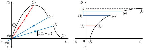
, in which damage translates into stiffness degradation. The concrete material is initially assumed to be elastic, isotropic, and with constant stiffness. The stiffness of the material is modified throughout the loading cycle through a scalar damage parameter (
), which ranges from 0 for an intact material to 1 for a material with no residual strength. Mazars’ models account for micro- and macro-effects caused by loading, rearrangement of concrete particles, the collapse of the micro-voids in the mixture, and the interaction of the cement matrix with the aggregates.
Figure 1 describes the behavior of stress-strain curves for concrete elements using damage models. Two unique damage-based models with different levels of sophistication were investigated in this study. For reference, key features of both models are summarized next. The reader is referred to Mazars
| [19] | Mazars, J. 1984. Application de la Mecanique de L'endommangement au Compportement non Lineaire et a la Ruptura du Beton de Structure. These de Doctorate d'Etat, L. M. T., Universite Paris, France. |
[19]
and Mazars et al.
| [23] | Mazars, J., Hamon, F., and Grange, S. 2015. A New 3D Damage Model for Concrete Under Monotonic, Cyclic and Dynamic Loading. Materials and Structures, 48: 3779-3793. https://doi.org/10.1617/s11527-014-0439-8 |
[23]
for complete information concerning these two models.
Figure 1. Stress-Strain Relationship of Damaged-Based Concrete.
2.1. Scalar Damage Model
Mazars
| [19] | Mazars, J. 1984. Application de la Mecanique de L'endommangement au Compportement non Lineaire et a la Ruptura du Beton de Structure. These de Doctorate d'Etat, L. M. T., Universite Paris, France. |
[19]
formulated a Scalar Damage (SD) model to predict the triaxial behavior of concrete. The damage parameter (
D) is calculated starting from an equivalent strain, which is calculated as the average of the tensile principal strains of the element. The calculation of the stress vector, {
, from the strain vector, {
, follows elastic theory, modified with an effective damage parameter (
) to reduce the secant stiffness matrix [
<i></i><i></i>:
To define the secant stiffness matrix, a plane stress assumption is utilized. This assumption is valid for situations where the material can freely expand or contract in the thickness direction (out of plane stress components are zero), and all external loads are applied in the plane perpendicular to the thickness direction. From this assumption, the secant stiffness matrix relating the stresses to the strains of an elastic isotropic material can be simplified to the following:
(2)
Where and are the Young’s modulus and Poisson’s ratio of the material, respectively. The damage of the element is given by the weighted sum of the damage produced by the tensile and compressive stresses, expressed as follows:
(3)
Both weights feature a parameter
that accounts for the presence of shear in the biaxial state of stress of the material, which can be taken as 0.6 based on experimental data
| [19] | Mazars, J. 1984. Application de la Mecanique de L'endommangement au Compportement non Lineaire et a la Ruptura du Beton de Structure. These de Doctorate d'Etat, L. M. T., Universite Paris, France. |
[19]
. In Eq. (
3),
and
represent the fraction of tensile and compressive strains (
and
, respectively), to the equivalent strain
. The equivalent strain is calculated as the average of the tensile principal strains of the element. Both
and
are damage parameters that depend on the shape of the concrete stress-strain tensile and compressive relationships, respectively. While damage in tension is taken to initiate at the onset of cracking, damage in compression initiates immediately.
2.2. μ Model
The
model
| [23] | Mazars, J., Hamon, F., and Grange, S. 2015. A New 3D Damage Model for Concrete Under Monotonic, Cyclic and Dynamic Loading. Materials and Structures, 48: 3779-3793. https://doi.org/10.1617/s11527-014-0439-8 |
[23]
is an extension of the SD model by adding the ability to capture stiffness recovery due to crack-cracking effects and was created to independently capture the damage caused by tension and compression in the material. Therefore, this model utilizes two independent equivalent strains, one for tension and another for compression, rather than a single equivalent strain as featured in the scalar damage model. Due to its ability to account for the direction of loading, the
model can capture stiffness recovery due to crack-closing effects (e.g., in a case in which the tensile straining becomes compressive), rendering the model suitable for cyclic loading. As in the scalar damage model, the stress in the material is obtained with Eq. (
1) while the damage parameter is expressed as:
(4)
Referring to Eq. (
4), the variable
is dependent on the damage strain threshold defined for deformations in compression and tension, while
Y represents the combination of tensile and compressive damage and is expressed as:
Where
and
are the maximum values of deformation reached during the loading path, and the triaxial factor (
r) varies from 0 for pure compressive stress to 1 for pure tensile stress
. The variables
and
in Eq. (
4) define the evolution of the effective damage parameter
, based on the material-specific parameters
,
,
, and
, as follows:
(6)
(7)
The parameter
featured in Eq. (
6) accounts for the shear sliding effects related to friction whenever the concrete is cracked and can be taken as 0.7 while maintaining good accuracy over a wide range of loading combinations
| [23] | Mazars, J., Hamon, F., and Grange, S. 2015. A New 3D Damage Model for Concrete Under Monotonic, Cyclic and Dynamic Loading. Materials and Structures, 48: 3779-3793. https://doi.org/10.1617/s11527-014-0439-8 |
[23]
.
3. Performance Investigations
The material formulations presented above were implemented into the open-source, freely available, finite-element software OpenSees
| [24] | McKenna, F., and Fenves, G. 2001. The OpenSees command language manual: Version 1.2. Berkeley, CA: Univ. of California, Pacific Earthquake Engineering Center. |
[24]
. Three types of analysis models were developed and validated with experimental data: (1) RC beam under monotonic and cyclic load; (2) RC shear wall subjected to cyclic load; and (3) full-scale RC building under earthquake excitation. The new materials were used in conjunction with the multilayered shell element
ShellMITC4 | [16] | Lu, X., Xie, L., Guan, H., and Lu, X. 2015. A Shear Wall Element for Nonlinear Seismic Analysis of Super-Tall Buildings Using OpenSees. Finite Element in Analysis and Design., 98: 14-25. https://doi.org/10.1016/j.finel.2015.01.006 |
[16]
available in the OpenSees library, which is a six-DOF, 3D element suitable to model membranes subjected to in- and out-of-plane loading.
3.1. RC Beam Under Monotonical Loading
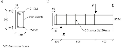
A simply supported beam built for this study was subjected to a monotonical four-point bending loading. The material properties of the concrete were a peak compressive strength (
) of 40 MPa, and a Young’s modulus (
) of 37.2 GPa. The yield stress of the steel (
) was measured as 475 MPa, with Young’s modulus (
) of 183.33 GPa. The dimensions and loading are shown in
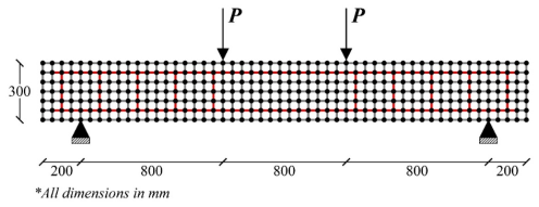
Figure 2. The concrete in the beam was modeled using 312 four-node multilayered shell elements (
ShellMITC4) while the steel reinforcement was modeled using truss elements.
Figure 2. Beam 1 (a) Cross-Sectional View (b) Span View.
Figure 3. Beam OpenSees Model.
Material properties of the reinforcing steel were defined using the pre-defined OpenSees material model
Steel02. The material model is the
Guiffré-Menegotto-Pinto steel model with isotropic strain hardening (based on the work of Menegotto and Pinto
| [25] | Menegotto, M. and Pinto, P. 1973. Method of analysis of cyclically loaded RC plane frames including changes in geometry and non-elastic behavior of elements under normal force and bending. IABSE Symposium on Resistance and Ultimate Deformability of Structures Acted on by Well-Defined Repeared Loads. Lisbon, Portugal. |
[25]
). The concrete behavior was modeled using each of the two damage models described above. Parameters used to define the concrete damage models were obtained by calibrating the model to the experimentally obtained concrete stress-strain relationship and are presented in
Table 1 below.
Table 1. Concrete-Damage Model Parameters for Monotonic Beam Analysis.
Model | (MPa) | (GPa) | | | | | | | |
SD | 40 | 37.2 | 0.18 | - | 0.00005 | 0.73 | 1065 | 0.97 | 10,000 |
μ | 40 | 37.2 | 0.18 | 0.0004 | 0.00005 | 0.65 | 280 | 0.97 | 10,000 |
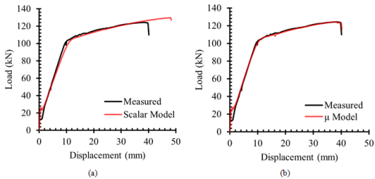
A comparison between the experimental and analytical obtained load-displacement curves is displayed in
Figure 4. Both models effectively captured the experimental failure mode which was the concrete crushing on the compressive side of the beam. It is observed that while both damaged-based models demonstrate an accurate prediction of peak load before failure, only the μ model was capable of capturing the correct displacement at failure. Additionally, both models overestimate the cracking load of the concrete which can be attributed to possible damage sustained by the beam specimen during transport into the loading fixtures and the condition that the post-peak tension curve is dependent on the size of the element specified.
Figure 4. Analysis Results of Monotonically-Loaded RC Beam (a) SD Model (b) μ Model.
3.2. RC Shear Wall Under Cyclic Loading
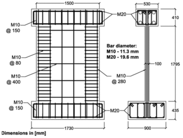
The performance of the damage models to simulate the behavior of an RC shear wall under reversed-cyclic loading was investigated next. A 100 mm x 1500 mm x 1795 mm cantilevered RC shear wall specimen (
Figure 5) experimentally tested by Hiotakis
| [9] | Hiotakis, S. 2004. Repair and Strengthening of Reinforced Concrete Shear Walls for Earthquake Resistance Using Externally Bonded Carbon Fibre Sheets and a Novel Anchor System. MSc Thesis Dissertation. Carleton University, Ottawa, ON. |
[9]
was selected to validate the two models. The wall was designed to exhibit ductile behavior, precluding shear failure. The reinforcement ratio of the wall was 0.8% and 0.5% in the vertical and horizontal directions, respectively. Material tests specified the concrete peak compressive strength was 36.2 MPa, while the yield stress of the longitudinal and transverse reinforcing steel bars was 425 MPa and 651 MPa, respectively.
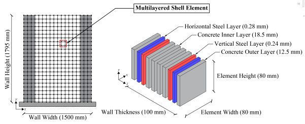
The shear wall OpenSees model was defined using 414 four-node rectangular, multilayered shell elements with a size of 80 x 80 mm (deemed appropriate based on a mesh sensitivity analysis in which five mesh sizes were analyzed). Using these shell elements, a shear wall reinforced with different reinforcement curtains in different directions can be efficiently modeled, as shown in
Figure 6. Each reinforcement curtain is modeled as a smeared layer of steel. As the boundaries of the wall featured additional reinforcement, a thicker steel layer was specified for these ‘boundary elements’ which correspond to the shaded elements in
Figure 6.
Figure 6. FE Model of RC Shear Wall.
Material properties of the reinforcing steel were defined using the preexisting OpenSees material model
Steel02 similar to the steel definition of the RC beam above. The concrete behaviour was modeled using each of the two damage models described above. Parameters used to define the concrete damage models were determined in the same manner as the previous study and are presented in
Table 2 below.
Table 2. Concrete-Damage Model Parameters for Cyclic Shear Wall Analysis.
Model | (MPa) | (GPa) | | | | | | | |
SD | 36.2 | 27.1 | 0.18 | - | 0.0001 | 1.25 | 2250 | 0.97 | 10000 |
μ | 36.2 | 27.1 | 0.18 | 0.0004 | 0.00001 | 1.25 | 650 | 0.97 | 10000 |
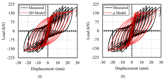
The calculated and measured load-displacement response of the shear wall for the SD model and the
model is presented in
Figure 7. It is noted that the listed displacement was measured at the top of the wall. The maximum strength and displacement calculated at each cycle with both models showing a reasonable correspondence with the measured results. A common observation concerning both models is the underestimation of residual displacements after each cycle. This was expected as the concrete damage models used in this study do not account for permanent strains, which results in the unloading and reloading paths after each cycle to return to the origin of the stress-strain relationship. The residual displacements observed in the figures are solely attributed to the plastic deformation in the steel reinforcement. It is also observed that both models underestimate the peak load of each cycle after yielding has occurred and the pinching of the curve. This is due to the defined material model of the steel reinforcement neglecting any strain hardening (which impacts the peak load) and the lack of bond-slip definition which influences the pinching of each cycle
| [21] | Mazars, J. and Grange, S. 2014. Simplified Method Strategies Based on Damage Mechanics for Engineering Issues. EUROC 2014, St Anton am Arlberg, Austria. https://doi.org/10.1201/b16645-110 |
| [22] | Mazars, J. and Grange, S. 2015. Modeling of Reinforced Concrete Structural Members for Engineering Purposes. Computers and Concrete, 16(5): 683-701. https://doi.org/10.12989/cac.2015.16.5.683 |
[21, 22]
.
Figure 7. Measured vs Calculated Load-Displacement Response (a) Scalar Damage Model (b) μ Model.
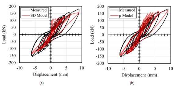
Looking at the load-displacement response of the first 12 cycles (
Figure 8) it is seen that the SD model significantly overestimates the applied load of the initial cycles. This can be attributed to the SD model calculating damage solely based on equivalent tensile strains, resulting in no damage initiation until after cracking has occurred. With the initial cycles within the elastic region, cracking has yet to occur, and in turn, no damage has been applied. The
model does not have this limitation however as equivalent compressive strains are added within the damage formulation, allowing for compressive damage to be calculated and accounted for continuously since the onset of loading. As a result, the
model can predict the force that causes the first crack, the overall strength, and the loading and unloading paths of the wall with more accuracy when compared to the SD model.
Figure 8. Measured vs Calculated First 12 Cycles of the Load-Displacement Response (a) Scalar Damage Model (b) Model.
3.3. Out-of-Plane Response of an RC Slab
The damage-based materials discussed in Section 2 can describe the 2D concrete response under a biaxial state of stress, which is most commonly utilized in capturing the behaviour of elements such as shear walls loaded in-plane. However, it is possible to approximate the out-of-plane response by incorporating the 2D damage-based materials together with a suitable shell element. In OpenSees, the
ShellMITC4 element has a multi-layer shell formulation based on the theory of mixed interpolation of tensorial components
| [7] | Dvorkin, E., Pantuso, D., and Repetto, E. 1995. A formulation of the MITC4 shell element for finite strain Elasto-plastic analysis. Comput. Methods Appl. Mech. Engrg., 125: 17-40. https://doi.org/10.1016/0045-7825(95)00767-U |
[7]
. The thickness of the
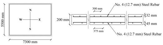
ShellMITC4 element is discretized into several fully bonded layers. The out-plane forces and displacements are obtained by integrating the axial stresses and curvatures in each layer, respectively, using a plane-section assumption. The axial stress is the normal stress in the biaxial model, perpendicular to the shell thickness. To investigate the out-of-plane performance of the materials, a numerical experiment was conducted in which a 200 mm thick, 7300 mm x 5500 mm rectangular slab, fixed on all four sides, was subjected to a uniform gravity load. The slab is reinforced with 4 layers of reinforcement, with the same amount of reinforcement in the E-W and N-S directions (
Figure 9).
Figure 9b depicts the reinforcing details in the middle of the slab, along with both ends. The material properties for steel and concrete were chosen to be the same as in Section 3.1.
Figure 9. RC Slab Details (a) Plan View (b) Cross-Section.
Using the same rationale from the previous examples, the slab was modeled in OpenSees with 220 ShellMITC4 elements, 20 in the E-W direction, and 11 in the N-S direction, with the concrete represented by the model. The same slab was modeled using the LimitState:SLAB commercial software. In LimitState:SLAB, yield-line theory is used to iteratively determine a collapse mechanism for slab systems and the associated ultimate capacity. The OpenSees analysis led to an ultimate capacity of 27.9 kPa, while LimitState:SLAB predicted 29.2 kPa, which shows good agreement between the two approaches. This provides evidence that biaxial damage-based materials, coupled with the use of a multi-layered shell element, can provide a reasonable estimation of ultimate strength in the out-of-plane direction. As the basis of yield-line theory assumes elastic behavior prior to the yield line formations/structural collapse, displacements cannot be predicted by the theory alone or by LimitState:SLAB which implements the theory. As such, no comparisons between the FE model and LimitState:SLAB can be made.
3.4. Full-Scale RC Building Under Seismic Loading
A full-scale, four-story, reinforced concrete building was tested on the E-Defense shake table in Japan
| [26] | Nagae, T., Ghannoum, W., Kwon, J., Tahara, K. Fukuyama, K. Matsumori, T., and Shiohara, H. 2015. Design Implications of Large-Scale Shake-Table Test on Four-Storey Reinforced Concrete Building. ACI Struct. J., 112(S12): 135-146. https://doi.org/10.14359/51687421 |
[26]
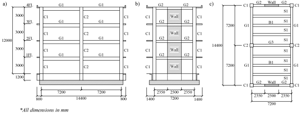
. This is one of the few full-scale 3D reinforced concrete shear wall structures in which the displacement inputs and outputs are available in the literature. The plan view and the longitudinal and transverse elevation views of the structure are shown in
Figure 10. The height of each storey was 3 m, while the plan size was 14.4 m in the longitudinal direction (L) and 7.2 m in the transverse direction (T). The lateral-force resisting system consisted of a two-bay RC moment frame system in the longitudinal direction on axes 1 and 2. In the transverse direction, a pair of multi-story RC shear walls were incorporated within a moment-resisting frame in exterior axes A and C, and a single-bay moment-resisting frame in the middle axis B.
Figure 10. Four-Storey Building (a) Longitudinal Elevation (b) Transverse Elevation and (c) Plan View.
The structure was designed using the seismic provisions of the Japanese Code
| [1] | AIJ. 1999. Design Guidelines for Earthquake Resistant Reinforced Concrete Buildings Based on the Inelastic Displacement Concept. Architectural Institute of Japan (AIJ). Tokyo, Japan. |
[1]
. The columns had a 500 x 500 mm square cross-section while the girders G1, G2, and G3 had rectangular cross-sections with dimensions of 300x600 mm, 300x300 mm, and 300x400 mm, respectively. The beam B1 had a rectangular cross-section of 300x400 mm. The 250 mm thick shear walls had a rectangular cross-section with dimensions of 2500x3000 mm. All floor slabs were 120 mm thick.
The steel reinforcement of each section varied according to the story level, with greater percentage ratios in the bottom floors compared to the top floors. The columns had a vertical reinforcement ratio () ranging between 1.21% - 1.52%, and a transverse reinforcement ratio () between 0.47-0.63%. The girders and beams were doubly reinforced, with similar amounts of reinforcement at the top and bottom layers. The girders had a longitudinal reinforcement percentage (), in either of the layers ranging between 0.74-1.06%. The transverse reinforcement ratio (), ranged between 0.26%-0.52%. Beams B1 had , equal to 1.42%, and equal to 0.26%. The slabs were reinforced with four layers of reinforcement, two at the top and two at the bottom. The reinforcement ratio of each layer in the transverse direction was 0.33%, while it was 0.26% in the longitudinal direction.
Concrete peak strengths measured during the test averaged 37.5 MPa. The yield strength of the longitudinal reinforcement was 392 MPa, and the average transverse/hoop reinforcement yield strength was 540 MPa. The weight of the building floors was reported as 867 kN for the second floor, 872 kN for the third floor, 867 kN for the fourth floor, and 934 kN for the roof, resulting in a total estimated weight of 3,540 kN for the structure. The Kobe records for the 1995 Hyogoken-Nanbu earthquake served as the input ground motions for the test. During the test, the intensity of the motions was gradually increased to observe the sequential damage to the structure. The intensity increments for the Kobe record were 25%, 50%, and 100%.
3.4.1. Finite Element Model
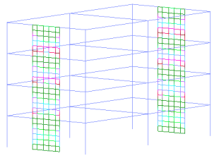
An analytical model of the full structure was created in OpenSees (
Figure 11). The girders, beams, and columns were modeled using
nonlinearBeamColumn elements made up of concrete and steel fibres. Confinement effects provided by hoop and transverse reinforcement were considered using Mander’s model
. The slab was assumed to be rigid enough so that a rigid diaphragm could be used to simulate its structural response, using multi-point constraint objects linking all the nodes in a given floor. The shear walls were modeled with multilayered
ShellMITC4 elements described above.
Figure 11. FE Model of the Full-Scale RC Building.
Smeared steel reinforcement was used for the multilayered shell elements of the shear walls. The concrete material used for the frame elements of the girders and columns was Kent-Scott-Park concrete material
| [31] | Scott, M., Park, R., and Priestley, M. 1982. Stress-Strain Behavior of Concrete Confined by Overlapping Hoops at Low and High Strain Rates. ACI Struct. J., 79(1): 13-27. https://doi.org/10.14359/10875 |
[31]
which implements a more simplified linear damage model when compared to the
damage model. The steel material used for modeling the reinforcement of all elements was the
Giuffre-Menegotto-Pinto steel material with isotropic strain hardening
| [25] | Menegotto, M. and Pinto, P. 1973. Method of analysis of cyclically loaded RC plane frames including changes in geometry and non-elastic behavior of elements under normal force and bending. IABSE Symposium on Resistance and Ultimate Deformability of Structures Acted on by Well-Defined Repeared Loads. Lisbon, Portugal. |
[25]
. The μ model material was chosen to model the shear walls as it demonstrated a better prediction of the cyclic behavior of a shear wall than the scalar damage model as discussed in Section 3.2. The base of the structure was assumed to be perfectly fixed, as the foundation blocks were secured with steel anchors to the steel base of the shake table.
The loading pattern was divided into two steps: (1) the gravitational load of the floors and the slabs was applied and kept constant on the beams and girders, upper ends of the columns, and walls, followed by (2) the ground motion applied to the base nodes. A transient analysis was performed using the Modified Newton algorithm, with the UmfPack integrator to solve the system of equations. The damping was defined using Rayleigh damping of 5% in the first three modes of vibration. The nodal displacements of each floor were recorded at each converged step.
3.4.2. Comparison Between Analytical and Experimental Data
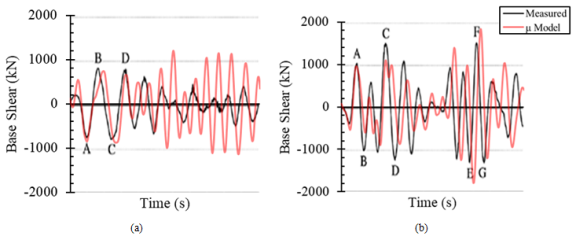
The global base-shear force (measured and calculated) for the 25% and 50% Kobe records is presented in
Figure 12 and
Figure 13, respectively, for both the longitudinal and transverse directions. In both the 25% and 50% Kobe records, the calculated magnitude of the global base shear response in the transverse (shear wall) direction demonstrated a close prediction with measured results. However, in the longitudinal (frames) direction the magnitude of the base shear appears reasonable for the first half of the response, while being noticeably overestimated in the second half of the response. This observation can be attributed to the longitudinal direction consisting solely of frame elements, which do not incorporate the
concrete damage model. Referring to the transverse direction, which features shear walls containing the
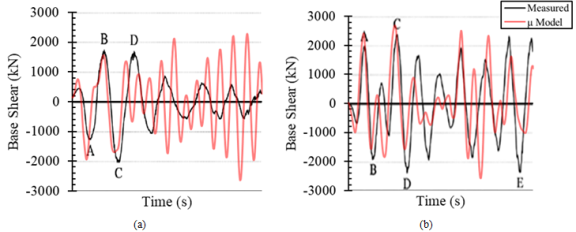
model, a better correlation between the FE model and measured response in the second half of the response is observed. It is also noted that the assumption of rigid diaphragm behavior would strongly condition the behavior in the longitudinal direction due to the three rows of support provided by the RC columns.
Figure 12. RC Building Global Base Shear Response for the 25% Kobe Record in (a) Longitudinal Direction and (b) Transverse Direction.
Figure 13. RC Building Global Base Shear Response for the 50% Kobe Record in (a) Longitudinal Direction and (b) Transverse Direction.
The measured and calculated maximum roof displacements are presented in
Table 3. For the 25% and 50% records, the roof displacements are underestimated in both directions. The difference percentage in the longitudinal direction is constant for the different Kobe magnitude records, whereas in the transverse direction the error percentage increases as the magnitude of the record increases. This can be explained by the limitation that the model does not account for bond-slip occurring at the bottom of the shear walls and the shake table flexibility, which was not accounted for in the model but has been shown to influence behavior
| [30] | Richard, B., Voldoire, F., Fontan, M., Mazars, J., Chaudat, T., Abouri, S., and Bonfils, N. 2018. SMART 2013: Lessons Learned from the International Benchmark About the Seismic Margin Assessment of Nuclear RC Buildings. Engineering Structures. 161(2018): 207-222. https://doi.org/10.1016/j.engstruct.2018.02.023 |
[30]
. Similar to the global base shear response, the calculated results feature a higher stiffness than the measured results, which translates to less energy dissipation.
Table 3. Maximum Roof Displacements of the RC Building.
KOBE Magnitude | Measured (mm) | Calculated (mm) | Difference (%) |
| Longitudinal | Transverse | Longitudinal | Transverse | Longitudinal | Transverse |
25% | 16.9 | 24.2 | 8.99 | 15.97 | 46.8 | 34.0 |
50% | 122.4 | 106.9 | 65.27 | 62.75 | 46.7 | 41.3 |
The calculated results had greater stiffness than the measured results, as indicated by the smaller deformations and higher strength responses. This can be explained in part by the inability of the model to account for bond-slip at the base of the walls and to predict shear deformations for the 1D frame elements. A better prediction is observed for the base-shear in the shear wall direction (transverse), concluding that the μ model is a reliable tool for predicting the behavior of 3D elements for full-scale structures. Despite the limitations discussed, the calculated results present a reasonable prediction for both the 25% and 50% intensity ground motion, resembling the actual behavior of the structure.
Author Contributions
Jesus Salazar Lopez: Conceptualization, Data curation, Formal Analysis, Investigation, Methodology, Software, Validation, Writing – original draft
Bernardo Garcia Ramirez: Methodology, Resources, Software
Clayton Pettit: Data curation, Formal Analysis, Methodology, Project administration, Resources, Software, Supervision, Validation, Visualization, Writing – original draft, Writing – review & editing
Carlos Cruz-Noguez: Conceptualization, Data curation, Formal Analysis, Funding acquisition, Investigation, Methodology, Project administration, Resources, Software, Supervision, Validation, Writing – original draft