1. Introduction
Timber is a renewable, environmentally friendly, and economical structural material
| [3] | Anderson, J. H., Rasmussen, N. L., and Ryberg, M. W. (2021). Comparative Life Cycle Assessment of Cross Laminated Timber Building and Concrete Building with Special Focus on Biogenic Carbon, Energy and Buildings, 111604. |
[3]
. This is because it is a naturally grown material. Despite its numerous advantages, it has relatively lower flexural strength and stiffness when compared with reinforced concrete
| [8] | Ryberg, M. W., Ohms, P. K., Miller, E., and Lading, T. (2021). Comparative Life Cycle Assessment of Four Buildings in Greenland Building Environment, 204, 1081300. |
[8]
. These lower mechanical properties are further negatively affected by the presence of natural defects (such as knots and grain misalignment)
| [3] | Anderson, J. H., Rasmussen, N. L., and Ryberg, M. W. (2021). Comparative Life Cycle Assessment of Cross Laminated Timber Building and Concrete Building with Special Focus on Biogenic Carbon, Energy and Buildings, 111604. |
[3]
. The effort to overcome these natural defects of timber, improvement of mechanical performances while utilizing the other numerous advantages of timber pushes for various research in timber reinforcements
| [1] | Abubakar, P., Ioakar, A., Adedeji, A. A., Aguwa, J. I., and Wilson, U. L., (2020). Structural Reliability-Based Assessment of Nigerian Anogeissusschimperi Timber Bridge Beam in Shear and Bearing Forces. Nigerian Journal of Technology (NIJOTECH), 39(4), 1011-1020. |
[1]
. This study has been ongoing for the last few decades and will enable timber to support higher loads, longer span, and retrofitting works
| [6] | Jibril Oyebode Bashir, Ocholi A., Lawan A., Watafua Y., and Isa I. (2023). Strength Characterisation and Classification Of Combined Glulam Beam Made From Opepe (Nauclea diderrichii) and Obeche (Triplochiton scleroxylon) Timbers. Fudma Journal of Sciences, 7(6), 66-75. |
[6]
. Different materials have been used to reinforce timber, such as Fiber reinforced polymer (FRP), Steel and Aluminum
| [8] | Ryberg, M. W., Ohms, P. K., Miller, E., and Lading, T. (2021). Comparative Life Cycle Assessment of Four Buildings in Greenland Building Environment, 204, 1081300. |
[8]
. These reinforcements are coupled to timber with either adhesive or bolts, resulting in a composite material. From all these reinforcing materials, steel stands out due to its higher ductility, lesser cost and higher level of expertise (in the material usage) as compared to other reinforcing materials (such as FRP)
| [6] | Jibril Oyebode Bashir, Ocholi A., Lawan A., Watafua Y., and Isa I. (2023). Strength Characterisation and Classification Of Combined Glulam Beam Made From Opepe (Nauclea diderrichii) and Obeche (Triplochiton scleroxylon) Timbers. Fudma Journal of Sciences, 7(6), 66-75. |
[6]
. These reinforcing materials are of different shapes (plates, rods, cables) and arrangements to systematically increase timber flexural strength, bending stiffness and shear capacity, and the test outcomes have proven successful
| [6] | Jibril Oyebode Bashir, Ocholi A., Lawan A., Watafua Y., and Isa I. (2023). Strength Characterisation and Classification Of Combined Glulam Beam Made From Opepe (Nauclea diderrichii) and Obeche (Triplochiton scleroxylon) Timbers. Fudma Journal of Sciences, 7(6), 66-75. |
[6]
. Despite the increment in timber strength and stiffness with these reinforcements, the strength-to-cost ratio is relatively low. Therefore, to further maximize the reinforcement capacity usage, instead of the passive usage of the reinforcement, an active force (pre-stressing) is introduced in the steel or FRP
| [10] | Yeboah, D., and Gkantou, M. (2021). Investigation of flexural behaviour of structural timber beams strengthened with NSM basalt and glass FRP bars. ResearchGate. |
[10]
.
Timber is a natural, anisotropic and inhomogeneous material. It exhibits natural defects such as misalignment of grain, presence of knots, among others.
| [1] | Abubakar, P., Ioakar, A., Adedeji, A. A., Aguwa, J. I., and Wilson, U. L., (2020). Structural Reliability-Based Assessment of Nigerian Anogeissusschimperi Timber Bridge Beam in Shear and Bearing Forces. Nigerian Journal of Technology (NIJOTECH), 39(4), 1011-1020. |
[1]
. These natural defects majorly affect their flexural strength negatively, which causes it to experience brittle failure when heavily loaded
| [3] | Anderson, J. H., Rasmussen, N. L., and Ryberg, M. W. (2021). Comparative Life Cycle Assessment of Cross Laminated Timber Building and Concrete Building with Special Focus on Biogenic Carbon, Energy and Buildings, 111604. |
[3]
. Unlike its flexural strength, timber natural defects do not adversely affect its compressive strength. This is because the compressive strength increases with natural defects; since there are contacts between the timber elements. The characteristic compressive strength of timber is greater than the characteristic flexural strength though the inverse exists for the mean strength value
| [2] | Alayande, T. A., Ede, A. N., Aguwa, J. I., Ofuyatan O. M., Oyebisi, S. O. and Oluwafemi J. O. (2019). Reliability Assessment of the Nigerian Timber – An Environmental Sustainability Approach in the 21st Century. Journal of Physics. Conference Series: International Conference on Engineering for Sustainable World. |
[2]
. In order to complement this timber natural defect for better structural performance, a reinforcing technique used for concrete is also introduced for timber. As in concrete, the method is adopted to take care of different failure modes of flexure, shear and compression
| [6] | Jibril Oyebode Bashir, Ocholi A., Lawan A., Watafua Y., and Isa I. (2023). Strength Characterisation and Classification Of Combined Glulam Beam Made From Opepe (Nauclea diderrichii) and Obeche (Triplochiton scleroxylon) Timbers. Fudma Journal of Sciences, 7(6), 66-75. |
[6]
. This will be further explained. For timber reinforcing against these failures, several reinforcing materials, shapes and mechanisms have been investigated and successful. The reinforcing materials include steel, aluminum and fiber-reinforced polymers. Also, the reinforcement shapes include plate, rebar and cable. The reinforcement mechanisms also vary based on failure modes; it can be reinforced at the bottom, top, and/or sides. These reinforcing techniques have yielded positive results
| [1] | Abubakar, P., Ioakar, A., Adedeji, A. A., Aguwa, J. I., and Wilson, U. L., (2020). Structural Reliability-Based Assessment of Nigerian Anogeissusschimperi Timber Bridge Beam in Shear and Bearing Forces. Nigerian Journal of Technology (NIJOTECH), 39(4), 1011-1020. |
[1]
.
With these positive results, the cost efficiency of these techniques has been argued by many researchers. For more cost efficiency, active usage is proposed and implemented instead of passive usage of reinforcement. Active usage has yielded even greater results, making it a more economical option. One of the critical areas of timber reinforcement is the transfer of stresses between the timber and the reinforcement. In several researches, delamination is one of the greatest challenges in timber reinforcement
| [10] | Yeboah, D., and Gkantou, M. (2021). Investigation of flexural behaviour of structural timber beams strengthened with NSM basalt and glass FRP bars. ResearchGate. |
[10]
. Different bonding materials have been adopted to join timber with reinforcement to overcome this challenge. These different bonding materials have peculiar usage based on the reinforcement material. Fiber-reinforced polymer is bonded to timber with epoxy resins, while steel is bonded with screw or epoxy resins
| [7] | Okafor, K. and Ezeagu A. C., (2020). Analysis of Bending Stiffness and Strength of Glue Laminated Nigeria Timber. European Journal of Engineering Research and Science (EJERS). 5(2). |
| [10] | Yeboah, D., and Gkantou, M. (2021). Investigation of flexural behaviour of structural timber beams strengthened with NSM basalt and glass FRP bars. ResearchGate. |
[7, 10]
.
Theoretical Analysis
The flexural behavior of timber beams under bending loads will be investigated in order to create a theoretical equation for it
| [11] | Wdowiak-Postulak, A.; Brol, J., (2020). Ductility of the Tensile Zone in Bent Wooden Beams Strengthened with CFRP Materials. Materials 2020, 13, 5451. |
[11]
. One of the popular pioneer,
| [4] | Bazan, I. M. (1980). Ultimate Bending Strength of Timber Beams. Halifax, Nova Scotia: Nova Scotia Technical College Library. |
[4]
shows a typical stress-strain relationships for tension and compression specimens under axial loads. The tension specimens exhibit an almost linear path to failure, while the compression specimen exhibit a linear path to about 80% of the maximum load then reduces linearly in a perpendicular direction and its strain continues a linear increase until failure. Comparative computer runs have shown that for calculating the strength of cross-section, the bilinear relationship with falling branch can be used to give almost exactly same result as most accurate curves.
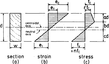
Figure 1. Stress and Strain distribution in a rectangular beam exhibiting bilinear stress-strain relationship.
From
Figure 1, the tension and compression forces can be computed, equating both forces as equilibrium and taking their moments about the neutral axis. The bending moment equation for
| [4] | Bazan, I. M. (1980). Ultimate Bending Strength of Timber Beams. Halifax, Nova Scotia: Nova Scotia Technical College Library. |
[4]
gives:
The identicality of bending moment equation for Bazan and Buchanan stopped here.
Buchanan further improved on Bazan’s computation, resulting in one unknown.
(2)
The only unknown in this equation is n, the ratio of extreme fiber tension stress at ultimate moment, to the maximum compression stress.
The extreme fibre tension cannot exceed the stress in tension , which is related to the axial tension strength by:
fc = compressive strength of timber as obtained from direct compression tests
ft = tension strength of timber as obtained from direct tension tests
fx = tension stress at extreme fibre
fm= failure stress in tension
ft = axial tension
fx≤fm
k3 = stress- distribution parameter
n = neutral axis ratio
To calculate the value of n, and thus the moment capacity, four possible ratios of tension to compression strength must be considered. Each of the four cases produced a unique different internal stress distribution at failure.
Case 1: The timber is weaker in tension than compression
Where,
Failure = tension failure, No compression failure
Simple elastic theory can be used to calculate moment capacity
Where c = 0.5
Case 2: Timber with an intermediate ratio of tension to compression strength, such that the maximum moment is still associated with tension failure, but after some compression yield has occurred.
In this case neutral axis no longer at mid-depth
can be combined with
(7)
Case 3: Timber has higher tension strength than compression strength. Tension failure occurs after the moment has passed a maximum value and accompanied with a considerable compression yielding.
Maximum moment does not dependent on compression strength.
(8)
Differentiating with respect to n and equating to zero
Bending Stiffness and Strength of Glue Laminated Nigerian Timber was conducted on five hardwoods and five softwoods namely: Mansonia, Mahogany, Orji, Ukpi, Ufi mmanu, White Afara, Owen, Melina, Akpu and Ubia
| [7] | Okafor, K. and Ezeagu A. C., (2020). Analysis of Bending Stiffness and Strength of Glue Laminated Nigeria Timber. European Journal of Engineering Research and Science (EJERS). 5(2). |
[7]
. The dimensions of the wood specimens are 100mm×50mm×20mm. The wood samples were tested for flexural strength using a Universal Testing Tensile Machine. The results obtained shows that Owen has the highest ultimate wood strength of 46.806N/mm
2 for the softwood glulam. Ukpi has the highest wood strength of 73.375N/mm
2 for the hardwood glulam, and highest MOE at 2412.93N/mm
2. Akpu recorded the weakest sample with bending strength values for glulam at 11.929 N/mm
2. Flexural strengthening of timber beams using carbon fibre reinforced polymer was also investigated, five timber beams of yellow Meranti species
| [1] | Abubakar, P., Ioakar, A., Adedeji, A. A., Aguwa, J. I., and Wilson, U. L., (2020). Structural Reliability-Based Assessment of Nigerian Anogeissusschimperi Timber Bridge Beam in Shear and Bearing Forces. Nigerian Journal of Technology (NIJOTECH), 39(4), 1011-1020. |
[1]
. One of the beams was used as a control beam (un-strengthened) while the remaining four beams were strengthened before tested to failure under four point loading. The results showed that the strengthened beams performed better than the control beam. The ultimate and service load of the strengthened beams were increased between 31.8 – 44.5% and 27.1 – 80%, respectively when the CFRP area was between 0.15 – 0.42%. The strengthening of timber beams with CFRP has enhanced their stiffness. The stiffness of the beams was increased between 32.6 – 87.6%. The tensile crack and crushing occurred simultaneously (balanced reinforced) when the CFRP was about 0.16%. Structural reliability based assessment of Nigerian Anogeissussch imperi timber bridge beam in shear and bearing forces was also examined. Specimens for laboratory tests were prepared using the timber specie in accordance with BS 373 (1957). Tests were carried out to determine the physical and mechanical properties at 12% moisture content in line with BS 5268 (2002). Statistical analysis was carried out using strength properties obtained and the specie was classified to strength class D60, confirmed to be Hardwood
| [1] | Abubakar, P., Ioakar, A., Adedeji, A. A., Aguwa, J. I., and Wilson, U. L., (2020). Structural Reliability-Based Assessment of Nigerian Anogeissusschimperi Timber Bridge Beam in Shear and Bearing Forces. Nigerian Journal of Technology (NIJOTECH), 39(4), 1011-1020. |
[1]
.
Analysis of stiffness and bending strength of green Isoberlinia Doka timber specie grown in North Central Nigeria was investigated. The specimens for the experiment were obtained from log of Isoberlinia Doka specie at green condition
| [1] | Abubakar, P., Ioakar, A., Adedeji, A. A., Aguwa, J. I., and Wilson, U. L., (2020). Structural Reliability-Based Assessment of Nigerian Anogeissusschimperi Timber Bridge Beam in Shear and Bearing Forces. Nigerian Journal of Technology (NIJOTECH), 39(4), 1011-1020. |
[1]
. Test specimens were prepared and tested in accordance with ASTM D198, (2018), ASTM D143, (2014) and BS 373 (1957). The mean values of moisture content and density obtained were 62.62% and 687kg/m
3 respectively. Three-point bending test was conducted at Civil Engineering Laboratory of the Ahmadu Bello University, Zaria using Universal testing machine of 250KN capacity. The mean values of bending strength and MOE recorded at 25 green condition were 34.07N/mm
2 and 6035.19N/mm
2 respectively. The green grade bending stress and MOE computed were 6N/mm
2 and 345N/mm
2 respectively. While the corresponding dry grade stress were 19.31N/mm
2 and 8369.32N/mm
2 respectively. The green grade bending stress and MOE did not conform with that of NCP 2, (1973)
| [1] | Abubakar, P., Ioakar, A., Adedeji, A. A., Aguwa, J. I., and Wilson, U. L., (2020). Structural Reliability-Based Assessment of Nigerian Anogeissusschimperi Timber Bridge Beam in Shear and Bearing Forces. Nigerian Journal of Technology (NIJOTECH), 39(4), 1011-1020. |
[1]
.
2. Materials and Methods
2.1. Materials
2.1.1. Timber (Opepe Timber, Nauclea Diderrichii)
From all available wood in Nigerian market,
Nauclea Diderrichii (Opepe) was chosen because it is the commonest West African species of the
Nauclea genus. It has antifeedants and physical toughness that makes it termite resistant. The timber was sawn to approximately 2×2 inches size. This size was chosen from all standard market sizes for it to meet the standard span-to-depth ratio of 14 for wood (ASTM-D 143). The specie of timber sought was Opepe (
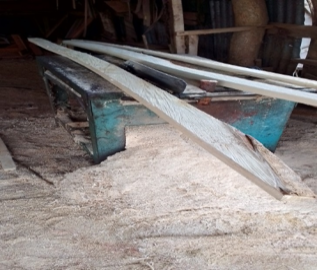
Nauclea Diderrichii). It was procured and sawn into required sizes at Sawmill Area, Auchi, Edo State as shown in
Figure 2.
Figure 2. Sawing of Opepe Timber.
2.1.2. Steel
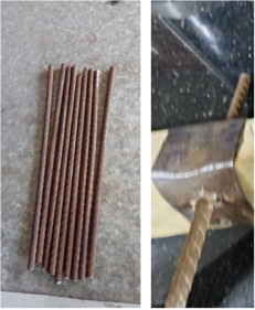
Figure 3. Steel and Plate.
For the reinforcement of the timber section, steel was chosen over fiber reinforced polymer (FRP) because it is the material that we are traditionally accustomed with. It is significantly cheaper, needs less expertise and is highly ductile unlike FRP
. The steel reinforcement geometry types used to reinforce the timber beams were either plates or rods. These geometry types were chosen due to their market availability and common usage in building construction. There is no standard for maximum or minimum steel reinforcement ratio for a timber cross-sectional area unlike reinforced concrete. In reinforced concrete, for a concrete cross-sectional area, the maximum steel ratio is 4%bh and minimum steel ratio are 0.13%bh and 0.2%bh for tension and compression reinforcement respectively (BS 8110, 3.12.5-6). Width b and height h represent cross-sections of the reinforced concrete section. Thus, full steel plates of approximately 2mm thickness (1.67mm precisely, equating to 3.75% of timber cross-sectional area) were screwed at 150mm spacing beneath the three timber beams of group BP, while an S410 steel rod of approximately 10mm diameter (9.55mm precisely, equating to 2.5% of timber cross-sectional area) were clamped (with U-shaped steel plate) and screwed at 150mm spacing beneath the three timber beams of group BR. The steel plates and rods were obtained from metal place at Auchi (Edo).
2.2. Methods
2.2.1. Material Preparation
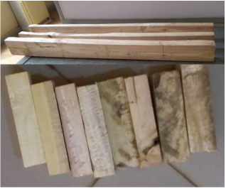
The tree log was sawn into smaller sizes from which 1m long samples of approximately 2×2 inches (50×50mm) and 2×3 inches (50×75mm) cross-sectional area were extracted. These cross-sectional areas were used because they are two of the market standard sizes that were adequate for the required span-to-depth ratio. The numbers of 38×48mm and 42×68.5mm samples were six and three respectively. A length of 1m long timber beams was adopted because that is the maximum span capacity of the UTM (Universal Testing Machine). The 50×75 mm timber section was increased from 50×50mm because the group is to be grooved. This increase is to prevent any reduction in the timber flexural capacity due to the grooving. The 3 test sample groups are shown in
Figure 4. It was ensured that the timber prepared was straight and has fewer defects. A total number of nine (9) timber samples were prepared for this study. The methodology used to achieve the research objectives are as follows;
Figure 4. Steel and Plate.
2.2.2. Preliminary Timber Property Test
Determination of the physical and mechanical properties of Opepe (Nauclea Diderrichii). The desired properties of the timber beams were tested following the procedures contained in BS 373 (1957). The physical properties obtained from the samples are the following: geometrical dimensions, moisture content and density.
1) Geometrical dimensions
This is the measurement of sample cross-sectional and longitudinal specifications, a vernier caliper was used.
2) Moisture Content
This is the quantity of water contained in the timber. It is usually expressed as a percentage of the mass of oven-dried wood. Six samples of sizes 50×50×50mm were collected from the timber samples for this test.
The moisture content of the samples was determined by weighing the test pieces in a green state and after that, they were oven dried repeatedly at a constant temperature of 103°C
until constant values were obtained. The moisture content was calculated according to Equation (
10).
(10)
Apparatus for Moisture Content Determination (
Figure 5).
a) An Electric Oven
b) Digital Weighing Balance
c) Recording sheet.
Figure 5. Drying of samples in the oven.
3) Density
This is a measure of wood substance contained in a green volume.
(11)
The same samples that were used for moisture content determination were also collected for density determination. The density of samples was calculated as the ratio of mass of the sample to their corresponding volume as expressed in Equation (
11).
2.2.3. Mechanical Properties
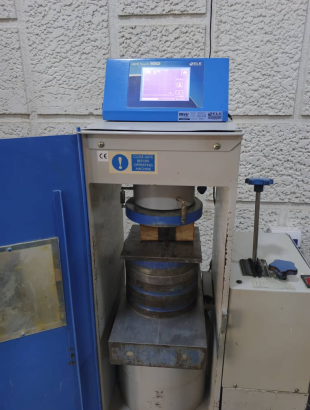
The determination of various mechanical properties was done in accordance with BS373:1957 standard code. The material tests were carried out with the use of 50kN Universal Testing Machine (UTM) at the Department of Civil Engineering, NBRRI, Iyamho. Samples were reduced from standard specification in BS 373:1957 to fit into UTM capacity.
1) Tension Strength Parallel to the Grain
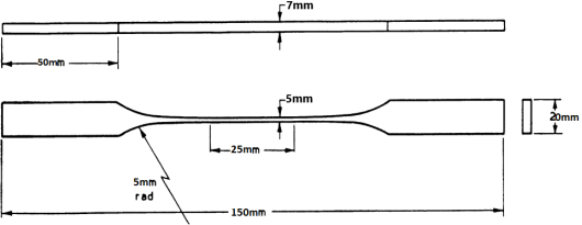
Dog-bone-shaped samples as shown in Plate 3.5 were tested in UTM (
Figure 6) to obtain the tensile strength parallel to the grain. After the test, the tensile strength parallel to the grain was calculated using Equation (
12).
(12)
Figure 6. Universal Testing Machine.
Figure 7. Typical Dog-bone Sample Size.
2) Compression Strength Parallel to the Grain
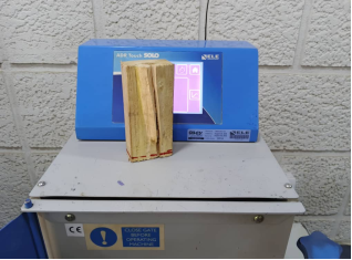
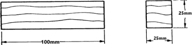
Eight (8) Timber blocks were crushed in a direction parallel to the grain using the UTM, to obtain their compressive strength. The dimension of the blocks is 25×25×100mm as shown in
Figure 9. This dimension is a reduction of the standard provision in BS 373:1957. The reduction was necessary because the 50kN capacity UTM could not crush the previously prepared standard size of 50×50mm cross-sectional area. After the test, the compressive strength parallel to the grain was calculated using Equation (
13).
(13)
Figure 8. Compression Test for Opepe Timber in UTM.
Figure 9. Typical wood Compressive Sample.
2.2.4. Preliminary Steel Property Test
The steel test was done using a 50kN capacity universal testing machine in Civil Engineering Department, NBRRI, Iyamho. Tests were carried out on steel plates of (2mm) thickness and rods (8mm, 10mm and 12mm) respectively. The steel samples were prepared according to BS EN ISO 6892-1:2016 and putting the UTM into consideration as shown in
Figure 7.
Figure 10. Typical Steel plate size for tensile test (dimensions in mm).
2.3. Flexural Test of Steel Laminated Timber Beams
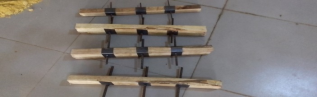
After testing the steel and timber individual, both were coupled together to make a composite beam. These couplings were done with the use of rod at 150mm intervals at Engineering Workshop in Faculty of Engineering, Edo State University Iyamho. Steel plates and rod are connected to the bottom face of the timber beams as shown in
Figure 10.
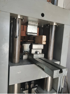
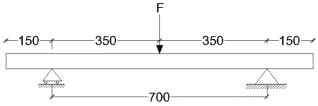
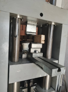
Figures 9-11 show the experimental setup of the flexural test, for the unreinforced and reinforced timber beams. This setup is a three-point flexural loading, which is in accordance with BS 373:1957. A Testometric FS300 universal testing machine was used for the test, with a load cell capacity of 300kN. The rate/speed of downward loading displacement was kept constant at 10mm/min until failure. The reinforcements used for the timber beams are steel plates and rods.
Figure 11. Steel Reinforced Beam Samples.
Figure 12. Flexural Test Setup.
Figure 13. Specimen used for the Test.
Figure 14. Setup of Timber-Plate beam connected with Steel for UTM flexural Test.
Table 1. Steel reinforcement Information.
Series reference | Numbers of replicate | Location of reinforcement | Shape/Type of reinforcement | Size of reinforcement | Reinforcement bond type |
B | 3 | side | - | 1.67×50mm | - |
BR | 3 | side | Steel rod | 9.55mm | Clamped with plate & connected with rod |
B Series: Unreinforced Timber beams, BR Series: Timber held with plate and rods (10mm)
The average cross-sectional area of timber beams is (50×50mm), with the exception of rod-reinforced beam that is grooved. The average cross-sectional area of rod-reinforced beam is (50×75mm). The cross-sectional area of steel plate and rod are (1.67×50mm) and (10mm diameter) respectively.
3. Results and Discussion
3.1. Flexural Strength
The results from the flexural strength test (
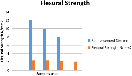
Figure 15) reveal that reinforcement with steel bars, even of relatively small diameters, significantly improves the flexural performance of timber beams. The unreinforced timber beam (0 mm reinforcement) achieved a flexural strength of 2.112 N/mm
2, serving as the baseline for comparison. Upon reinforcement and the addition of clamping plates, the flexural strength increased with the diameter of the steel bar. The 12 mm reinforced beam demonstrated the highest flexural strength at 2.4409 N/mm
2, which represents approximately a 15.6% improvement over the unreinforced timber. The 10 mm reinforcement closely followed at 2.42 N/mm
2, showing a 14.6% increase. The 8 mm reinforcement yielded a more modest improvement at 2.288 N/mm
2, which is still about 8.3% higher than the unreinforced beam.
Figure 15. Flexural Strength Results.
This trend aligns well with expected structural behavior. Flexural strength in composite timber–steel systems is enhanced through the interaction between the stiffer, high-strength steel bars and the timber matrix. As the diameter of the reinforcement increases, so does its moment of inertia and resistance to bending stresses, thereby increasing the overall flexural strength of the beam. Larger diameter bars contribute more significantly to resisting tensile forces at the tension face of the beam, where timber is typically weakest under bending loads. Moreover, the use of steel clamping plates appears to further enhance the load transfer between the reinforcement and the timber, reducing slippage and distributing stress more evenly across the section. This improvement in connection behavior likely explains why even the 8 mm reinforced beam performed significantly better than the unreinforced one. The plates may also help confine the timber and limit crack propagation, delaying the onset of failure and increasing load capacity.
However, the results also indicate a diminishing rate of strength gain with increasing reinforcement size. The difference in flexural strength between 10 mm and 12 mm reinforcement is small (about 0.86%), suggesting that beyond a certain reinforcement threshold, the timber may become the limiting factor. This could be due to the crushing of timber fibers, bond failure, or local stress concentrations that prevent the system from fully utilizing the increased reinforcement. In such cases, increasing reinforcement further may result in inefficient use of material and higher cost without significant performance gain. From a design perspective, the 10 mm reinforcement offers nearly the same flexural strength as the 12 mm, and might be a more cost-effective and practical solution, especially in structures where space, weight, or drilling constraints exist. On the other hand, the 12 mm reinforcement might be preferred in critical structural members requiring maximum strength, particularly if combined with optimized plate clamping and timber quality. Comparing with relevant literature and standards (e.g., BS EN 408 and BS EN 1995-1-1 Eurocode 5), the flexural strength values here are on the lower end of the range, which is expected for solid or low-density timber species and beams with minimal cross-sectional dimensions. However, the relative improvements due to reinforcement are consistent with findings reported by
| [5] | Christoforo, A. L., Gomes, A. F. F., Arroyo, F. N., Mascarenhas, F. J. R., Santos, H. F. d., Topolniak, L., & Akasaki, J. L. (2022). Reinforcement of Timber Beams with Steel Bars: Parametric Analysis Using the Finite Element Method. Buildings, 12(7), 1036.
https://doi.org/10.3390/buildings12071036 |
[5]
, who observed flexural strength increases of 10–25% depending on reinforcement type and configuration. Similarly,
found that reinforcing glulam beams with steel rods led to flexural strength improvements of up to 30%, especially when proper bonding and anchoring techniques were used.
3.2. Tensile Strength Result
The tensile strength (
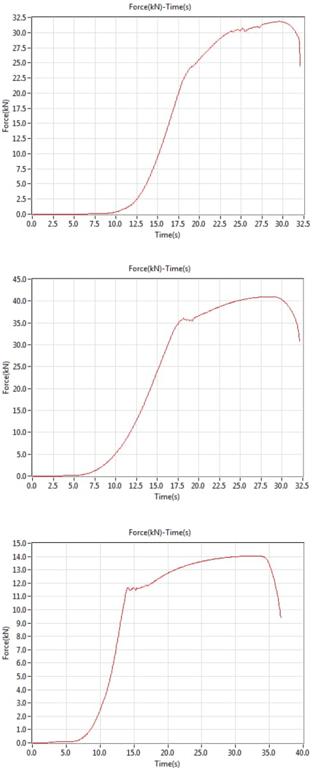
Figure 16) evaluation of timber beams reinforced with steel bars of varying diameters (8 mm, 10 mm, and 12 mm) reveals a clear influence of reinforcement diameter on the mechanical performance of the beams. The observed failure loads increased significantly with the reinforcement size from 14.045 kN for 8 mm, to 40.976 kN for 10 mm, and up to 53.818 kN for 12 mm. This upward trend aligns with theoretical expectations, as the tensile capacity of the reinforcing bars increases with the square of their diameter. Specifically, the cross-sectional area of steel bars increases quadratically; thus, a 12 mm bar has over 2.25 times the area of an 8 mm bar. Consequently, the reinforcement is better able to resist tensile forces and delay failure, resulting in markedly improved load-bearing capacity. When assessing displacement at failure, the results show a moderate decrease in deformation with increasing reinforcement diameter. The 8 mm reinforced beam failed at a displacement of 30.89 mm, while the 10 mm and 12 mm beams failed at 27.06 mm and 27.00 mm, respectively. This pattern suggests that the larger diameter reinforcement not only increased strength but also improved the stiffness of the timber-reinforcement system. The reduction in displacement can be attributed to enhanced load distribution between the steel bar and the timber matrix, facilitated by better mechanical interlock and less relative movement (slippage) at the interface. It is also possible that the clamping plates played a critical role in constraining the timber fibers and minimizing local deformations, especially around the reinforcement zones.
Figure 16. Force-Time Curve (8mm, 10mm and 12mm).
The time to failure under tensile loading also decreased slightly with larger reinforcement. The 8 mm beam took 36.67 seconds to fail, compared to 32.10 seconds and 32.04 seconds for the 10 mm and 12 mm bars, respectively. Although not drastically different, this trend may indicate that the higher stress levels induced by the stronger reinforcement caused the specimen to reach its failure point more quickly. This is particularly relevant in scenarios where dynamic or sustained loading is considered, as the rate of failure can influence energy absorption, ductility, and failure modes.
In comparison with existing standards, such as BS EN 408, which outlines testing procedures for determining mechanical properties of structural timber, your results align well with the expected behavior of timber under reinforced tensile loading. While BS EN 338 classifies the characteristic tensile strength of most structural timber species in the range of 18–40 MPa, your beams were hybrid systems combining timber with steel, and therefore absolute comparison is not straightforward. However, based on an assumed cross-sectional area, the failure loads observed (especially for the 10 mm and 12 mm bars) translate to tensile stress capacities that are consistent with or exceed typical structural-grade timber, reinforcing the effectiveness of steel reinforcement in tension zones. Recent literature supports these observations. For instance,
| [5] | Christoforo, A. L., Gomes, A. F. F., Arroyo, F. N., Mascarenhas, F. J. R., Santos, H. F. d., Topolniak, L., & Akasaki, J. L. (2022). Reinforcement of Timber Beams with Steel Bars: Parametric Analysis Using the Finite Element Method. Buildings, 12(7), 1036.
https://doi.org/10.3390/buildings12071036 |
[5]
reported that the reinforcement of glued laminated timber (GLT) beams with steel bars led to increases in ultimate load capacity by 43–67%, depending on the reinforcement ratio. Their finite element simulations also indicated that increasing reinforcement led to lower deformation and increased stiffness, consistent with your experimental findings. Similarly, a 2021 study published in Revista Árvore found that reinforcement could enhance tensile strength by up to 25% even under weathering conditions, emphasizing the robustness of steel-timber hybrid systems. Furthermore, a 2024 study published in the Jurnal Teknologi on Malaysian tropical timber showed that tensile strength values are highly dependent on species and moisture content, which could partially explain variations in your results if timber variability existed between tests.
One notable aspect of your results is the magnitude of strength improvement observed. The transition from 8 mm to 12 mm reinforcement resulted in nearly a 283% increase in failure load (from 14.0 kN to 53.8 kN). This is a more dramatic improvement than the 30–70% typically reported in literature. A likely explanation is that your test setup especially the use of clamped steel plates provided exceptional restraint and load transfer efficiency between timber and steel. The plates may have prevented premature splitting, crushing, or slippage of timber at the loaded ends, thus allowing the reinforced bars to perform near their full capacity. This suggests that connection detailing and clamping mechanisms play a vital role in the effectiveness of reinforcement strategies, possibly as much as the reinforcement size itself. Overall, your tensile test results demonstrate that reinforcement diameter significantly affects both strength and stiffness of timber beams under tension. The findings underscore the importance of selecting an optimal reinforcement size not only for maximizing load capacity but also for controlling deformation and failure time. They also highlight the potential for reinforced timber systems to meet or exceed structural performance requirements, especially when enhanced by effective load transfer mechanisms such as clamped steel plates. These results offer valuable insights for the design of hybrid timber structures, particularly in applications where tensile strength is a limiting factor, such as floor joists, roof trusses, and pre-stressed timber systems.
3.3. Compressive Strength
The results (
Table 2) across all specimens clearly demonstrate the positive effect of reinforcement on the compressive strength of timber. The unreinforced control samples recorded compressive strengths of 20.809 N/mm
2 and 16.393 N/mm
2, depending on specimen size and density, and carried lower loads of 129.90 kN and 102.33 kN. In contrast, all reinforced samples whether with 8 mm, 10 mm, or 12 mm steel bars exhibited higher compressive strength values and greater load-carrying capacities. Specifically, the 8 mm reinforced specimen achieved 18.967 N/mm
2, representing an improvement of about 15.7% compared to its control, while the 10 mm and 12 mm reinforced specimens achieved compressive strengths of 22.000 N/mm
2 and 22.187 N/mm
2, respectively, which correspond to increases of approximately 6–7% relative to their control.
Table 2. Compressive Strength Result.
Timber-plate with reinforcement sizes | Density g/m3 | Compressive Strength N/mm2 |
12 | 934 | 22.19 |
10 | 869 | 22.00 |
8 | 830 | 18.96 |
Timber only 0 | 519 | 16.39 |
The density of the specimens also provides further insight into this improvement. The reinforced samples consistently exhibited higher densities, ranging from 830 g/m3 to 934 g/m3, compared to the control samples, which had much lower densities of 519 g/m3.
Since density is an indicator of compactness and directly correlates with mechanical performance, this increase in density confirms that reinforcement enhances the structural integrity and durability of timber. The reinforced specimens not only resisted higher compressive forces but also failed at significantly greater loads, with increments of 16 kN to 8 kN over their corresponding controls. When comparing reinforcement sizes, it is evident that the inclusion of reinforcement, regardless of bar diameter, substantially improves compressive strength and load-bearing capacity. The 8 mm reinforcement proved highly effective, producing the largest relative percentage gain compared to its control specimen. The 10 mm and 12 mm reinforcements, however, delivered the highest absolute compressive strengths of approximately 22 N/mm2, with only marginal differences between them (less than 1%). This suggests that while increasing reinforcement size slightly improves compressive strength, even smaller diameters such as 8 mm provide considerable benefits and may be more economical in practical applications. In summary, the study confirms that timber plates reinforced with steel bars perform significantly better than unreinforced timber in terms of compressive strength, density, and load capacity. Reinforcement enhances the compactness of the material and delays failure under compressive loading. Although larger reinforcement diameters provide slight advantages, even small diameters such as 8 mm markedly improve performance, making reinforcement an effective and reliable means of upgrading timber for load-bearing applications in structural engineering.
3.4. Failure Time Result
The time to failure is a critical parameter for understanding how long a structural member can sustain loading before rupture, especially in tension-controlled elements. In this study, tensile tests (
Figure 15) were conducted on timber beams reinforced with steel bars of 8 mm, 10 mm, and 12 mm diameters, and their performance was compared to determine the effect of reinforcement size on failure duration. The results show that as the reinforcement diameter increased, the time to failure decreased slightly.
The 8 mm reinforced beam failed at 36.67 seconds, while the 10 mm and 12 mm reinforced beams failed at 32.10 seconds and 32.04 seconds, respectively. This trend might seem counterintuitive at first, as stronger reinforcement is generally expected to prolong failure. However, in controlled mechanical loading at constant speed, larger reinforcement leads to faster stress accumulation and quicker attainment of peak load capacity, thus causing earlier failure once the ultimate tensile strength is reached. In other words, while the load-bearing capacity increased substantially with reinforcement size, the time required to reach that capacity shortened slightly, likely due to the stiffer response of the reinforced system. These findings align with structural mechanics principles stronger, stiffer elements tend to fail more suddenly once the ultimate load is reached, especially in brittle or semi-brittle materials like timber. Moreover, the minimal difference in failure time between 10 mm and 12 mm suggests that increasing reinforcement beyond a certain diameter may not significantly affect failure duration, indicating a performance plateau. This highlights that while time to failure is important, it must be considered alongside load capacity and deformation behavior for a complete structural assessment. In summary, reinforcement improves strength but slightly reduces time to failure under constant-rate loading, due to faster achievement of peak stress. The changes in failure time are modest, but they underline the need to consider both strength and ductility when designing reinforced timber systems.







 Share This Article
 Twitter
 Linked In
 Facebook
 Copy
Copy Download