In the construction of overhead distribution network lines, ensuring the stability and construction quality of utility pole foundations is crucial. Traditionally, this process may involve excavation and direct inspection, which is not only time-consuming but may also cause environmental damage. The non-destructive detection scheme proposed in this paper, based on the transient electromagnetic method (TEM), offers an efficient and non-intrusive method for detecting the burial conditions of utility pole bases, pulls, and chucks. The transient electromagnetic method is a geophysical exploration technique that uses the principle of electromagnetic induction to detect the distribution of underground materials. When detecting utility pole bases, this method analyzes the electromagnetic response generated by underground metallic structures to obtain information. However, traditional TEM has a blind zone problem in shallow metal detection, which limits its application in utility pole base inspection. To address this issue, the scheme proposed in this paper introduces a decoupling coil to eliminate interference caused by the primary magnetic field. This decoupling technology significantly improves the detection discrimination, allowing for a more accurate determination of the burial depth and condition of bases, pulls, and chucks. Finite element numerical analysis using COMSOL 5.4 is adopted to examine the underground magnetic field distribution and optimize coil parameters. This analysis helps to understand the interaction between the electromagnetic field and underground structures, guiding the design of coils and the development of detection strategies. The prototype experimental platform built further validates the effectiveness of the scheme. Experimental results include measured data of magnetic field variations, assessments of detection depth and resolution. These experimental results are crucial for verifying the practical application potential of the non-destructive detection scheme.
| Published in | Science Journal of Energy Engineering (Volume 12, Issue 1) |
| DOI | 10.11648/j.sjee.20241201.12 |
| Page(s) | 7-15 |
| Creative Commons |
This is an Open Access article, distributed under the terms of the Creative Commons Attribution 4.0 International License (http://creativecommons.org/licenses/by/4.0/), which permits unrestricted use, distribution and reproduction in any medium or format, provided the original work is properly cited. |
| Copyright |
Copyright © The Author(s), 2024. Published by Science Publishing Group |
Transient Electromagnetic (TEM) Method, Decoupling, Mental Detection, Non-Destructive Testing, Utility Pole, Base
Size (m) | Depth (m) | |
|---|---|---|
Utility pole | 15.00 | 3.00 |
Base | 0.60×0.53×0.15 | 3.00 |
Pull | 0.95×0.50×0.28 | 1.25 |
Chuck | 0.80×0.30×0.25 | 1.50 |
 (1)
(1)  (2)
(2)  (3)
(3)  (4)
(4)  (5)
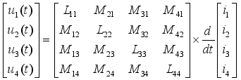
(5)  ,
,  ,
,  .
.  (6)
(6) 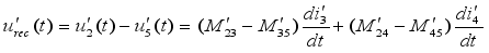 (7)
(7)  (8)
(8)  (9)
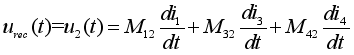
(9)  ,
,  ,
,  .
. 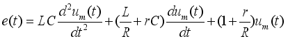 (10)
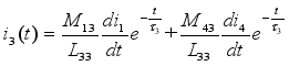
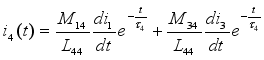
(10)  (11)
(11)  ,
,  ,
, 
 .
.  (12)
(12) TEM | Transient Electromagnetic Method |
BPC | Base, Pull and Chuck |
| [1] | Wang CY, Liang XD, Emerson PA, et al. Investigation of Seasonal Variations of Tower Footing Impedance in Transmission Line Grounding Systems. IEEE Transactions on Industry Applications 2021; 57(3): 2274-2284. |
| [2] | Alexandra I K, Bauyrzhan A U and Yurii V. T. Methodology for Analysing the Technical State and Residual Life of Overhead Transmission Lines. IEEE Transactions on Power Delivery 2021; 36(5): 2730-2739. |
| [3] | Smith RS, Annan AP, Lemieux J, et al. Application of a modified GEOTEM system to reconnaissance exploration for Kimber lites in the Point Lake area, NWT, Canada. Geophysics 1996; 61(1). 82–92. |
| [4] | Tang RJ, Li FS, Shen FL, et al. Fast Forecasting of Water-Filled Bodies Position Using Transient Electromagnetic Method Based on Deep Learning. IEEE Transactions on Geoscience and Remote Sensing 2024; 62: 4502013. |
| [5] | Chen J, Zhang Y and Lin TT. High-Resolution Quasi-Three-Dimensional Transient Electromagnetic Imaging Method for Urban Underground Space Detection. IEEE Transactions on Industrial Informatics 2023; 19(3): 3039-3046. |
| [6] | Witherly K, Irvine R, and Godbout M. Reid Mahaffy test site, Ontario Canada: An example of benchmarking in airborne geophysics. In: Proc. 74th Annu. Int. Meeting, Soc. Explor. Geophysicists, Denver, CO, USA, Oct, 2004, pp. 1202–1204. |
| [7] | Zhu X, Su X, Tai HM, et al. Bipolar steep pulse current source for highly inductive load. IEEE Trans. Power Electron 2016; 31(9): 6169–6175. |
| [8] | Wang Q, Wang H, Wu M, et al. esearch on Noise Suppression Method for Transient Electromagnetic Signal. In: IEEE Advanced Information Management, Communicates, Electronic and Automation Control Conference (IMCEC), 2018, pp. 394-397. |
| [9] | Yu C, Fu Z, Wu G, et al. Configuration Detection of Substation Grounding Grid Using Transient Electromagnetic Method. IEEE Transactions on Industrial Electronics 2017, 64(8): 6475-6483. |
| [10] | Qin SQ, Wang Y, Xu Z, et al. Fast Resistivity Imaging of Transient Electromagnetic Using ANN. IEEE Geoscience and Remote Sensing Letters 2019; 16(9): 1373-1377. |
| [11] | Gang Z, Rui X, Yu C, et al. Research on Double Coil Pulse Eddy Current Thickness Measurement. In: 2017 10th International Conference on Intelligent Computation Technology and Automation (ICICTA), 2017, pp. 406-409. |
| [12] | Shi X and Tao F. Research on the detection of high-resistivity body by transient electromagnetic method. In: Proceedings 2011 International Conference on Transportation, Mechanical, and Utilityal Engineering (TMEE), 2011, pp. 1103-1106. |
| [13] | Svatos J and Vedral J. The Usage of Frequency Swept Signals for Metal Detection. IEEE Transactions on Magnetics 2012, 48(4): 1501-1504. |
| [14] | Tie CJ, Weng CC, Aydiner AA., et al. Detection of buried targets using a new enhanced very early time electromagnetic (VETEM) prototype system. IEEE Transactions on Geoscience and Remote Sensing 2001; 39(12): 2702-2712. |
| [15] | Chang JH, Su BY, Malekian R, et al. Detection of Water-Filled Mining Goaf Using Mining Transient Electromagnetic Method. IEEE Transactions on Industrial Informatics 2019; 16(5): 2977-2984. |
| [16] | Qi ZP, Li X, Li H, et al. First Results From Drone-Based Transient Electromagnetic Survey to Map and Detect Unexploded Ordnance. IEEE Geoscience and Remote Sensing Letters 2020; 17(12): 2055-2059. |
| [17] | Su BY, Yu JC, Królczyk GM., et al. Innovative Surface-Borehole Transient Electromagnetic Method for Sensing the Coal Seam Roof Grouting Effect. IEEE Transactions on Geoscience and Remote Sensing 2022; 60: 5702509. |
| [18] | Wang LJ, Zhang S, Chen SD, et al. Fast Localization of Underground Targets by Magnetic Gradient Tensor and Gaussian-Newton Algorithm With a Portable Transient Electromagnetic System. IEEE Access 2021; 9: 148469-148478. |
| [19] | Zhang JL, Xiang XB and Li WJ. Advances in Marine Intelligent Electromagnetic Detection System, Technology, and Applications: A Review. IEEE Sensors Journal 2023; 23(5): 4312-4326. |
| [20] | Wang LJ, Zhang S and Chen SD. Underground Target Localization Based on Improved Magnetic Gradient Tensor With Towed Transient Electromagnetic Sensor Array. IEEE Access 2022; 10: 25025-25033. |
| [21] | Zhang XH, Pang XY, Yu SB, et al. A Broadband Multifrequency Resonance Compensator for Frequency-Domain Electromagnetic Prospecting Transmitting System. IEEE Transactions on Power Electronics 2024; 39(5): 5178-5193. |
| [22] | Liu LH, Qiao L, Liu LS, et al. Applying Stray Inductance Model to Study Turn-off Current in Multi-Turn Loop of Shallow Transient Electromagnetic Systems. IEEE Transactions on Power Electronics 2020; 35(2): 1711-1720. |
| [23] | Wu X, Xue GQ and He YM. The Progress of the Helicopter-Borne Transient Electromagnetic Method and Technology in China. IEEE Access 2020; 8: 32757-32766. |
| [24] | Oldenburg D W, Haber E and Shekhtman R. Three dimensional inversion of multisource time domain electromagnetic data. Geophysics 2013; 78(1): E47-E57. |
| [25] | Jiang ZH, Liu LB, Liu SC, et al. Surface-to-Underground Transient Electromagnetic Detection of Water-Bearing Goaves. IEEE Transactions on Geoscience and Remote Sensing 2019; 58(8): 5303-5318. |
| [26] | Xue GQ, Yu JC. New development of TEM research and application in coal mine exploration. Progress in Geophysics 2017; 32(1): 319-326. |
APA Style
Zhou, J., Tao, T., Xu, L., Zhi, Y. (2024). Detection of Underground Utility Pole Base for Distribution Transmission Network Based on Transient Electromagnetic Method. Science Journal of Energy Engineering, 12(1), 7-15. https://doi.org/10.11648/j.sjee.20241201.12
ACS Style
Zhou, J.; Tao, T.; Xu, L.; Zhi, Y. Detection of Underground Utility Pole Base for Distribution Transmission Network Based on Transient Electromagnetic Method. Sci. J. Energy Eng. 2024, 12(1), 7-15. doi: 10.11648/j.sjee.20241201.12
AMA Style
Zhou J, Tao T, Xu L, Zhi Y. Detection of Underground Utility Pole Base for Distribution Transmission Network Based on Transient Electromagnetic Method. Sci J Energy Eng. 2024;12(1):7-15. doi: 10.11648/j.sjee.20241201.12
@article{10.11648/j.sjee.20241201.12,
  author = {Jun Zhou and Tianyi Tao and Lingda Xu and Yonglin Zhi},
  title = {Detection of Underground Utility Pole Base for Distribution Transmission Network Based on Transient Electromagnetic Method
},
  journal = {Science Journal of Energy Engineering},
  volume = {12},
  number = {1},
  pages = {7-15},
  doi = {10.11648/j.sjee.20241201.12},
  url = {https://doi.org/10.11648/j.sjee.20241201.12},
  eprint = {https://article.sciencepublishinggroup.com/pdf/10.11648.j.sjee.20241201.12},
  abstract = {In the construction of overhead distribution network lines, ensuring the stability and construction quality of utility pole foundations is crucial. Traditionally, this process may involve excavation and direct inspection, which is not only time-consuming but may also cause environmental damage. The non-destructive detection scheme proposed in this paper, based on the transient electromagnetic method (TEM), offers an efficient and non-intrusive method for detecting the burial conditions of utility pole bases, pulls, and chucks. The transient electromagnetic method is a geophysical exploration technique that uses the principle of electromagnetic induction to detect the distribution of underground materials. When detecting utility pole bases, this method analyzes the electromagnetic response generated by underground metallic structures to obtain information. However, traditional TEM has a blind zone problem in shallow metal detection, which limits its application in utility pole base inspection. To address this issue, the scheme proposed in this paper introduces a decoupling coil to eliminate interference caused by the primary magnetic field. This decoupling technology significantly improves the detection discrimination, allowing for a more accurate determination of the burial depth and condition of bases, pulls, and chucks. Finite element numerical analysis using COMSOL 5.4 is adopted to examine the underground magnetic field distribution and optimize coil parameters. This analysis helps to understand the interaction between the electromagnetic field and underground structures, guiding the design of coils and the development of detection strategies. The prototype experimental platform built further validates the effectiveness of the scheme. Experimental results include measured data of magnetic field variations, assessments of detection depth and resolution. These experimental results are crucial for verifying the practical application potential of the non-destructive detection scheme.
},
 year = {2024}
}
TY  - JOUR
T1  - Detection of Underground Utility Pole Base for Distribution Transmission Network Based on Transient Electromagnetic Method

AU  - Jun Zhou
AU  - Tianyi Tao
AU  - Lingda Xu
AU  - Yonglin Zhi
Y1  - 2024/07/15
PY  - 2024
N1  - https://doi.org/10.11648/j.sjee.20241201.12
DO  - 10.11648/j.sjee.20241201.12
T2  - Science Journal of Energy Engineering
JF  - Science Journal of Energy Engineering
JO  - Science Journal of Energy Engineering
SP  - 7
EP  - 15
PB  - Science Publishing Group
SN  - 2376-8126
UR  - https://doi.org/10.11648/j.sjee.20241201.12
AB  - In the construction of overhead distribution network lines, ensuring the stability and construction quality of utility pole foundations is crucial. Traditionally, this process may involve excavation and direct inspection, which is not only time-consuming but may also cause environmental damage. The non-destructive detection scheme proposed in this paper, based on the transient electromagnetic method (TEM), offers an efficient and non-intrusive method for detecting the burial conditions of utility pole bases, pulls, and chucks. The transient electromagnetic method is a geophysical exploration technique that uses the principle of electromagnetic induction to detect the distribution of underground materials. When detecting utility pole bases, this method analyzes the electromagnetic response generated by underground metallic structures to obtain information. However, traditional TEM has a blind zone problem in shallow metal detection, which limits its application in utility pole base inspection. To address this issue, the scheme proposed in this paper introduces a decoupling coil to eliminate interference caused by the primary magnetic field. This decoupling technology significantly improves the detection discrimination, allowing for a more accurate determination of the burial depth and condition of bases, pulls, and chucks. Finite element numerical analysis using COMSOL 5.4 is adopted to examine the underground magnetic field distribution and optimize coil parameters. This analysis helps to understand the interaction between the electromagnetic field and underground structures, guiding the design of coils and the development of detection strategies. The prototype experimental platform built further validates the effectiveness of the scheme. Experimental results include measured data of magnetic field variations, assessments of detection depth and resolution. These experimental results are crucial for verifying the practical application potential of the non-destructive detection scheme.

VL  - 12
IS  - 1
ER  -
High Magnetic Group, Songshan Lake Mat Lab, Dongguan, China
High Magnetic Group, Songshan Lake Mat Lab, Dongguan, China
Baisha Power Supply Bureau, Hainan Power Grid Corporation, Haikou, China
Baisha Power Supply Bureau, Hainan Power Grid Corporation, Haikou, China
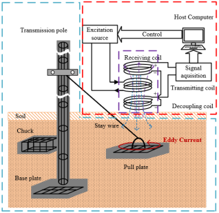
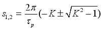
Figure 1. Schematic of detection object and system.
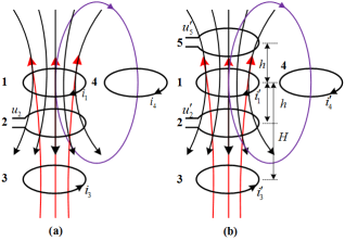
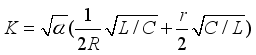
Figure 2. (a) the conventional TEM equivalent model. (b) TEM equivalent model with a decoupling coil.
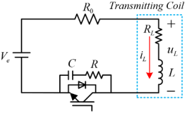
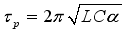
Figure 3. Schematic of the pulse current source circuit.
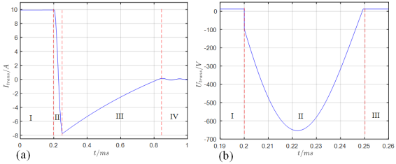
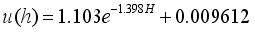
Figure 4. (a) Current waveform at falling edge. (b) Voltage waveform during stage II.
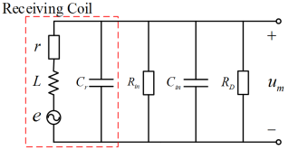
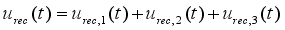
Figure 5. Equivalent circuit diagram of receiving coil.
Figure 6. Three-dimensional simulation model in COMSOL.
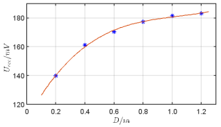
Figure 7. Correlation between coil diameter and peak receiving voltage.
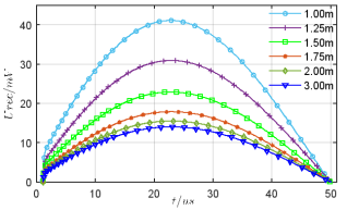
Figure 8. Receiving voltage waveform of simulation at falling edge.
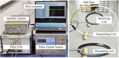
Figure 9. Prototype test platform for BPC Detection.
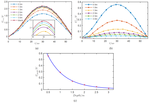
Figure 10. (a) Curves of receiving voltage with depth ranging from 0.5 m to 3.0 m. The curve, denoted “blank”, is obtained without detection objects. Due to ambient electromagnetic noise, receiving voltage curves are processed by taking 5 data sets for the mean filter in each depth scale. (b) Curves of the effective receiving voltage after subtracting the incomplete decoupling voltage. (c) Fitting curve of receiving voltage versus depth.
Information

