
For wide-area reconnaissance and surveillance systems, ultrawide field of view, real-time measurement and compact size are very important. This article presents a compact two-dimensional-ultrawide-field-of-view broadband high-spectral-resolution snapshot imaging spectrometer (2DUFBHSIS), which consists of an imaging microlens array, multiple optical fibers, seven identical collimating microlens arrays, seven identical optical filters, seven identical planar transmission gratings, and seven identical detectors. The imaging microlens array is divided into seven identical parts in the horizontal direction, each part coupled to a separate collimating microlens array through optical fibers. The 2DUFBHSIS employs a parallel architecture to effectively balance key performance requirements, including ultrawide field of view, broad spectral coverage, high spectral resolution, real-time spectral imaging and a compact overall design. The theoretical analysis and simulation results are provided to demonstrate the feasibility of the proposed concept. The 2DUFBHSIS can simultaneously achieve two-dimensional ultrawide-field-of-view (e.g. 105°×80°), broad spectral range (e.g. 350 nm), high spectral resolution (superior to 10 nm in the wavelength range of 400 nm to 750 nm), real-time measurement, and compact size (e.g. overall size is less than 130 mm × 100 mm × 100 mm). The 2DUFBHSIS has great potential for wide-area optical reconnaissance and surveillance on remote sensing platforms (e.g., unmanned aerial vehicles and helicopters).
| Published in | Optics (Volume 14, Issue 1) |
| DOI | 10.11648/j.optics.20261401.12 |
| Page(s) | 22-31 |
| Creative Commons |
This is an Open Access article, distributed under the terms of the Creative Commons Attribution 4.0 International License (http://creativecommons.org/licenses/by/4.0/), which permits unrestricted use, distribution and reproduction in any medium or format, provided the original work is properly cited. |
| Copyright |
Copyright © The Author(s), 2026. Published by Science Publishing Group |
Snapshot Imaging Spectrometer, Two-dimensional Ultrawide-field-of-view, Compact Size, Broad Spectral Range, High Spectral Resolution
 columns and
  rows of microlenses. Each row of MLA1 is arranged on circular arcs in different planes to obtain an ultrawide FOV in the horizontal plane in real time. Each column of MLA1 is arranged on circular arcs in different vertical planes to obtain an ultrawide FOV in the vertical plane in real time. Thus, the 2DUFBHSIS can obtain a 2D ultrawide FOV (e.g. 105°×80°) in real time.
  columns and
  rows of microlenses. The Part k of the MLA1 is coupled to microlens array MLA(k+1), and each microlens of the Part k of the MLA1 is coupled to a separate microlens ML(k+1) of microlens array MLA(k+1) through a separate fiber, where k =1, 2, …, 7.
  , grating
  , and finally is received by detector
  , where k =1, 2, …, 7.
  is the horizontal FOV of the 2DUFBHSIS,
  is the vertical FOV of the 2DUFBHSIS,
  is the FOV of each microlens of MLA1,
  is the focal length of each microlens of MLA1, and
  is the radius of the circular arcs formed by each column (row) of MLA1.
  of each microlens of MLA1 should be
 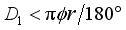 (1)
(1)  . The number of microlenses in each column of MLA1 is
  . The Part k of the MLA1 has a horizontal FOV of
  , a vertical FOV of
  , and contains
  columns and
  rows of microlenses.
  of the MLA1 and microlens array MLA(k+1). Figure 3 shows the schematic diagram of the positional relationship between the Part
  of the MLA1 and microlens array MLA(k+1).
  is the size in the x-axis direction of multiple microlenses ML(k+1) that are coupled with a column of the Part k of the MLA1.
  microlenses located in the
  column of the Part k of the MLA1 are respectively coupled to the microlenses ML(k+1) numbered
  , where
  .
.  . The angle between the optical axis of each microlens of MLA(k+1) and the normal of grating
  is
is  . The aperture size of each microlens of MLA(k+1) is
  . The focal length of each microlens of MLA(k+1) is
  . The center distance between two adjacent microlenses of MLA(k+1) is
  , where
  and
and  should be an integer multiple of the detector pixel size.
  (2)
(2)  (3)
(3)  (4)
(4)  to
to  allow only the light in the wavelength range
 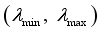 to pass through, where
  and
and  are the minimum and maximum wavelengths that can be resolved by the 2DUFBHSIS, respectively. The 2DUFBHSIS uses the first-order diffraction of the grating, so the spectral range of the 2DUFBHSIS must satisfy
 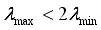 (5)
(5)  to
to  are located in the same plane parallel to the x-y plane. The grating grooves of grating
  to
to  are parallel to the x-axis. Detector
  to
to  are located in the x-y plane. Each column of detector
  is parallel to the y-axis. The grating
  is parallel to detector
  .
.  is the first wavelength (the minimum wavelength
  ) resolved by the 2DUFBHSIS,
  is the
  wavelength resolved by the 2DUFBHSIS,
  is the
  wavelength (the maximum wavelength
  ) resolved by the 2DUFBHSIS.
  is the number of wavelengths that can be resolved by the 2DUFBHSIS.
  is the pixel size of each detector.
  is the length in the y-axis direction of the illuminated region on detector
  for each wavelength resolved by the 2DUFBHSIS, and
 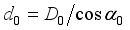 .
.  rows and
  columns, each block has a size of
  , and each block contains
  pixels. Each column of blocks in detector
  records spatial and spectral information of a separate object unit collected by a separate microlens of the Part k of the MLA1.
 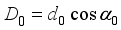 (6)
(6)  should satisfy
 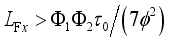 (7)
(7)  should be
 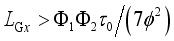 (8)
(8)  should be
  (9)
(9)  is
is 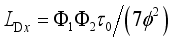 (10)
(10)  is
is  (11)
(11) 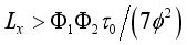 (12)
(12)  (13)
(13)  is the distance from the center of a microlens of MLA(k+1) to grating
  in the z-axis direction (perpendicular to the x-y plane), and
  is the distance in the y-axis direction between the lowest point on detector
  of the first-order diffracted light of the minimum wavelength
  and the grating normal located at the lowest point of grating
  surface illuminated by the incident parallel beam.
  (14)
(14)  is the distance between the straight line passing through the focal points of the two microlenses located at both ends of a row of the MLA1 and the plane formed by the focal points of all collimating microlenses.
  between grating
  and detector
  is
is  (15)
(15)  (16)
(16)  is the groove spacing (grating period) of grating
  , and
, and  is the spectral resolution of the 2DUFBHSIS at the minimum wavelength
  . In addition,
  is given by
  (17)
(17)  wavelength
  can be expressed as
 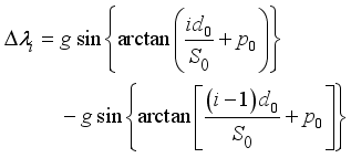 (18)
(18) 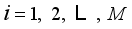 .
.  should also satisfy
 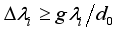 (19)
(19)  is approximately given by
 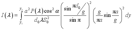 (20)
(20)  (21)
(21)  (22)
(22)  is the transmission width per grating period of transmission grating, and
  is the total intensity incident on grating
  at wavelength
  for the output beam of a microlens of MLA(k+1).
  is the alignment error angle of the collimating microlens array along the y-axis direction, the angle between the optical axis of each microlens of MLA(k+1) and the normal of grating Gk is
 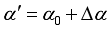 , and the angle of incidence to the grating Gk is
 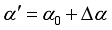 . The spectral resolution of the 2DUFBHSIS at the
  wavelength
  , including the alignment error of the collimating microlens array in the y-axis direction, can be approximately calculated by
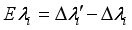
 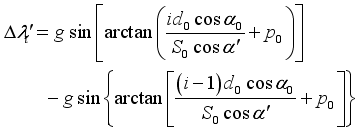 (23)
(23)  , generated by the alignment error of the collimating microlens array in the y-axis direction, can be given by
  (24)
(24)  should satisfy
 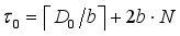 , where
  is a positive integer, and so the minimum value of
  is
is 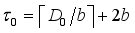 . In order to better eliminate the impact of the channel crosstalk and the alignment error in the x-axis direction, it can also be set as
 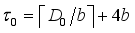 or
or 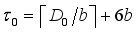 .
.  of each microlens of MLA1 needs to be increased, a 2D ultrawide FOV will lead to an increase in size of MLA1. To increase the optical throughput, the 2DUFBHSIS can slightly reduce the field of view to control the instrument size, making it better for wide-area optical reconnaissance and surveillance on remote sensing platforms.
 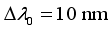 , the horizontal FOV is
  , the vertical FOV is
  , the FOV of each microlens of MLA1 is
  , and the pixel size of each detector is
 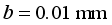 . The angular resolution is
  , the number of microlenses in each row of MLA1 is
 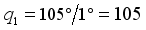 , the number of microlenses in each column of MLA1 is
 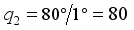 . Each part of MLA1 has a horizontal FOV of 15°, a vertical FOV of 80°, and contains 15 columns × 80 rows of microlenses. The radius of the circular arcs formed by each column (row) of MLA1 is
  . The aperture size of each microlens of MLA1 is
 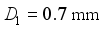 . The focal length of each microlens of MLA1 can be
 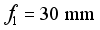 .
.  is
is  . The length in the y-axis direction of the illuminated region on detector
  for each wavelength resolved by the 2DUFBHSIS is
 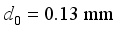 . The angle between the optical axis of each microlens in MLA(k+1) and the grating normal of grating
  is
is  . The distance between grating
  and detector
  is
is 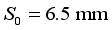 . In addition,
 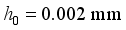 .
.  . The aperture size of each microlens of MLA(k+1) is
 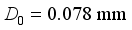 . The focal length of each microlens of MLA(k+1) can be
  . The center distance between two adjacent microlenses of MLA(k+1) can be
 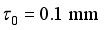 .
.  should satisfy
 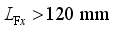 , so it can be
 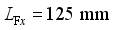 . The size of grating
  can be
 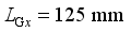 and
and  .
.  . The spectral resolution of the 2DUFBHSIS in the wavelength range from 400 nm to 750 nm is approximately 10 nm ~ 3.6 nm.
  can be small and
  , setting
  is sufficient to eliminate the impact of the channel crosstalk and the alignment error in the x-axis direction.
 2DUFBHSIS | Two-dimensional-ultrawide-field-of-view Broadband High-spectral-resolution Snapshot Imaging Spectrometer |
FOV | Field of View |
2D | Two-dimensional |
SGI | Static Grating Interferometer |
MLA1 | Imaging Microlens Array |
MLA2~MLA8 | Seven Identical Collimating Microlens Arrays |
MLA(k+1) | Collimating Microlens Array (k+1), Where k =1, 2, …, 7 |
ML(k+1) | A Microlens of the Collimating Microlens Array (k+1), where k =1, 2, …, 7 |
F1~F7 | Seven Identical Optical Filters |
Fk | Optical Filter k, Where k =1, 2, …, 7 |
G1~G7 | Seven Identical Planar Transmission Gratings |
Gk | Planar Transmission Grating k, where k =1, 2, …, 7 |
D1~D7 | Seven Identical Detectors |
Dk | Detector k, where k =1, 2, …, 7 |
| [1] | K. Miyamoto. Fish Eye Lens. J. Opt. Soc. Am. 1964, 54(8), 1060-1061. |
| [2] | L. Fan and L. Lu. Design of a simple fisheye lens. Appl. Opt. 2019, 58(19), 5311-5319. |
| [3] | I. Powell. Panoramic lens. Appl. Opt. 1994, 33(31), 7356-7361. |
| [4] | G. Kweon, K. T. Kim, G. Kim, and H. Kim. Folded catadioptric panoramic lens with an equidistance projection scheme. Appl. Opt. 2005, 44(14), 2759–2767. |
| [5] | J. H. Wang, Y. C. Liang, and M. Xu. Design of panoramic lens based on ogive and aspheric surface. Opt. Express 2015, 23(15), 19489-19499. |
| [6] | W. Song, X. Liu, P. Lu, Y. Huang, D. Weng, Y. Zheng, Y. Liu, and Y. Wang. Design and assessment of a 360° panoramic and high-performance capture system with two tiled catadioptric imaging channels. Appl. Opt. 2018, 57(13), 3429-3437. |
| [7] | C. Pernechele. Hyper Hemispheric Lens. Opt. Express 2016, 24(5), 5014-5019. |
| [8] | X. H. Wang, X. Zhong, R. F. Zhu, F. Gao, and Z. Q. Li. Extremely wide-angle lens with transmissive and catadioptric integration. Appl. Opt. 2019, 58(16), 4381-4389. |
| [9] | D. J. Brady and N. Hagen. Multiscale lens design. Opt. Express 2009, 17(13), 10659-10674. |
| [10] | D. J. Brady, M. E. Gehm, R. A. Stack, D. L. Marks, D. S. Kittle, D. R. Golish, E. M. Vera, and S. D. Feller. Multiscale gigapixel photography. Nature. 2012, 486(7403), 386-389. |
| [11] | E. J. Tremblay, D. L. Marks, D. J. Brady, and J. E. Ford. Design and scaling of monocentric multiscale imagers. Appl. Opt. 2012, 51(20), 4691-4702. |
| [12] | P. Llull, L. Bange, Z. Phillips, K. Davis, D. L. Marks, and D. J. Brady. Characterization of the AWARE 40 wide-field-of-view visible imager. Optica. 2015, 2(12), 1086-1089. |
| [13] | W. Pang and D. J. Brady. Galilean monocentric multiscale optical systems. Opt. Express 2017, 25(17), 20332-20339. |
| [14] | D. Brady, W. Pang, H. Li, Z. Ma, Y. Tao, and X. Cao. Parallel cameras. Optica. 2018, 5(2), 127-137. |
| [15] | G. M. Schuster, D. G. Dansereau, G. Wetzstein, and J. E. Ford. Panoramic single-aperture multi-sensor light field camera. Opt. Express 2019, 27(26), 37257-37273. |
| [16] | J. Duparré, P. Dannberg, P. Schreiber, A. Braüer, and A. Tünnermann. Artificial apposition compound eye fabricated by micro-optics technology. Appl. Opt. 2004, 43(22), 4303-4310. |
| [17] | K. H. Jeong, J. Kim, and L. P. Lee. Biologically inspired artificial compound eyes. Science, 2006, 312(5773), 557-561. |
| [18] | L. Li and A. Y. Yi. Development of a 3D artificial compound eye. Opt. Express 2010, 18(17), 18125-18137. |
| [19] | Y. Song, Y. Xie, V. Malyarchuk, J. Xiao, I. Jung, K. Choi, Z. Liu, H. Park, C. Lu, R. Kim, R. Li, K. B. Crozier, Y. Huang, and J. A. Rogers. Digital cameras with designs inspired by the arthropod eye. Nature. 2013, 497(7447), 95-99. |
| [20] | W. Lee, H. Jang, S. Park, Y. M. Song, and H. Lee. COMPU-EYE: a high resolution computational compound eye. Opt. Express 2016, 24(3), 2013-2026. |
| [21] | W. L. Liang, J. G. Pan, and G. D. J. Su. One-lens camera using a biologically based artificial compound eye with multiple focal lengths. Optica. 2019, 6(3), 326-334. |
| [22] | I. Stamenov, A. Arianpour, S. J. Olivas, I. P. Agurok, A. R. Johnson, R. A. Stack, R. L. Morrison, and J. E. Ford. Panoramic monocentric imaging using fiber-coupled focal planes. Opt. Express 2014, 22(26), 31708-31721. |
| [23] | A. Arianpour, N. Motamedi, I. P. Agurok, and J. E. Ford. Enhanced signal coupling in wide-field fiber-coupled imagers. Opt. Express 2015, 23(4), 5285-5299. |
| [24] | S. J. Olivas, A. Arianpour, I. Stamenov, R. Morrison, R. A. Stack, A. R. Johnson, I. P. Agurok, and J. E. Ford. Image processing for cameras with fiber bundle image relay. Appl. Opt. 2015, 54(5), 1124-1137. |
| [25] | N. Motamedi, S. Karbasi, J. E. Ford, and V. Lomakin. Analysis and characterization of high-resolution and high-aspect-ratio imaging fiber bundles. Appl. Opt. 2015, 54(32), 9422-9431. |
| [26] | N. Motamedi, V. Lomakin, and J. E. Ford. Image restoration in fiber-coupled imagers using space-variant impulse response characterization. Appl. Opt. 2017, 56(14), 4003-4011. |
| [27] | W. M. Porter and H. T. Enmark. A System Overview of the Airborne Visible/Infrared Imaging Spectrometer (Aviris). Proc. SPIE 1987, 834, 22-31. |
| [28] | R. W. Basedow, D. C. Carmer, and M. E. Anderson. HYDICE system: implementation and performance. Proc. SPIE 1995, 2480, 258-267. |
| [29] | Y. Shen, Q. Yang*, B. Li. Ultrawide-field-of-view ultrahigh-spectral-resolution imaging spectrometer based on a grating-beamsplitter interferometer. Opt. Commun. 2025, 579, 131543. |
| [30] | Q. Yang. Design study of a compact ultra-wide-angle high-spatial-resolution high-spectral-resolution snapshot imaging spectrometer. Opt. Express 2021, 29(2), 2893-2908. |
| [31] | D. Mengu, A. Tabassum, M. Jarrahi, and A. Ozcan. Snapshot multispectral imaging using a diffractive optical network. Light Sci. Appl. 2023, 12(5), 789-808. |
| [32] | W. Zhang, J. Suo, K. Dong, L. Li, X. Yuan, C. Pei, and Q. Dai. Handheld snapshot multi-spectral camera at tens-of-megapixel resolution. Nat. Commun. 2023, 14, 5043. |
| [33] | Q. Yang. Static broadband snapshot imaging spectrometer. Opt. Eng. 2013, 52, 053003. |
| [34] | Q. Yang. Compact static infrared broadband snapshot imaging spectrometer. Chin. Opt. Lett. 2013, 12, 031201. |
| [35] | Q. Yang. Broadband high-resolution line-imaging spectrometer with a large working distance range. Opt. Commun. 2025, 583, 131802. |
| [36] | Y. Chen, J. Liang, B. Zhao, W. Yue, K. Zheng, Y. Zhao, Y. Qin, H. Nie, W. Wang, and J. Lv. Snapshot infrared Fourier transform imaging spectrometer for transient dynamic sensing. Opt. Express 2025, 33(3), 4024-4043. |
| [37] | J. Zhu, H. Nie, L. Wang, B. Zhao, K. Zheng, Y. Zhao, Y. Chen, W. Ning, P. Sun, X. Du, S. Ma, Y. Qin, W. Wang, J. Liang, and J. Lv. Snapshot hyperspectral imaging with high spatial resolution based on transformers. Opt. Express 2025, 33(15), 31731-31755. |
APA Style
Yang, Q., Wang, Z. (2026). Compact Two-dimensional-ultrawide-field-of-view Broadband High-spectral-resolution Snapshot Imaging Spectrometer. Optics, 14(1), 22-31. https://doi.org/10.11648/j.optics.20261401.12
ACS Style
Yang, Q.; Wang, Z. Compact Two-dimensional-ultrawide-field-of-view Broadband High-spectral-resolution Snapshot Imaging Spectrometer. Optics. 2026, 14(1), 22-31. doi: 10.11648/j.optics.20261401.12
@article{10.11648/j.optics.20261401.12,
  author = {Qinghua Yang and Zhipeng Wang},
  title = {Compact Two-dimensional-ultrawide-field-of-view Broadband High-spectral-resolution Snapshot Imaging Spectrometer},
  journal = {Optics},
  volume = {14},
  number = {1},
  pages = {22-31},
  doi = {10.11648/j.optics.20261401.12},
  url = {https://doi.org/10.11648/j.optics.20261401.12},
  eprint = {https://article.sciencepublishinggroup.com/pdf/10.11648.j.optics.20261401.12},
  abstract = {For wide-area reconnaissance and surveillance systems, ultrawide field of view, real-time measurement and compact size are very important. This article presents a compact two-dimensional-ultrawide-field-of-view broadband high-spectral-resolution snapshot imaging spectrometer (2DUFBHSIS), which consists of an imaging microlens array, multiple optical fibers, seven identical collimating microlens arrays, seven identical optical filters, seven identical planar transmission gratings, and seven identical detectors. The imaging microlens array is divided into seven identical parts in the horizontal direction, each part coupled to a separate collimating microlens array through optical fibers. The 2DUFBHSIS employs a parallel architecture to effectively balance key performance requirements, including ultrawide field of view, broad spectral coverage, high spectral resolution, real-time spectral imaging and a compact overall design. The theoretical analysis and simulation results are provided to demonstrate the feasibility of the proposed concept. The 2DUFBHSIS can simultaneously achieve two-dimensional ultrawide-field-of-view (e.g. 105°×80°), broad spectral range (e.g. 350 nm), high spectral resolution (superior to 10 nm in the wavelength range of 400 nm to 750 nm), real-time measurement, and compact size (e.g. overall size is less than 130 mm × 100 mm × 100 mm). The 2DUFBHSIS has great potential for wide-area optical reconnaissance and surveillance on remote sensing platforms (e.g., unmanned aerial vehicles and helicopters).},
 year = {2026}
}
TY  - JOUR
T1  - Compact Two-dimensional-ultrawide-field-of-view Broadband High-spectral-resolution Snapshot Imaging Spectrometer
AU  - Qinghua Yang
AU  - Zhipeng Wang
Y1  - 2026/07/24
PY  - 2026
N1  - https://doi.org/10.11648/j.optics.20261401.12
DO  - 10.11648/j.optics.20261401.12
T2  - Optics
JF  - Optics
JO  - Optics
SP  - 22
EP  - 31
PB  - Science Publishing Group
SN  - 2328-7810
UR  - https://doi.org/10.11648/j.optics.20261401.12
AB  - For wide-area reconnaissance and surveillance systems, ultrawide field of view, real-time measurement and compact size are very important. This article presents a compact two-dimensional-ultrawide-field-of-view broadband high-spectral-resolution snapshot imaging spectrometer (2DUFBHSIS), which consists of an imaging microlens array, multiple optical fibers, seven identical collimating microlens arrays, seven identical optical filters, seven identical planar transmission gratings, and seven identical detectors. The imaging microlens array is divided into seven identical parts in the horizontal direction, each part coupled to a separate collimating microlens array through optical fibers. The 2DUFBHSIS employs a parallel architecture to effectively balance key performance requirements, including ultrawide field of view, broad spectral coverage, high spectral resolution, real-time spectral imaging and a compact overall design. The theoretical analysis and simulation results are provided to demonstrate the feasibility of the proposed concept. The 2DUFBHSIS can simultaneously achieve two-dimensional ultrawide-field-of-view (e.g. 105°×80°), broad spectral range (e.g. 350 nm), high spectral resolution (superior to 10 nm in the wavelength range of 400 nm to 750 nm), real-time measurement, and compact size (e.g. overall size is less than 130 mm × 100 mm × 100 mm). The 2DUFBHSIS has great potential for wide-area optical reconnaissance and surveillance on remote sensing platforms (e.g., unmanned aerial vehicles and helicopters).
VL  - 14
IS  - 1
ER  -
School of Optoelectronic Engineering, Xidian University, Xi’an, China
Command and Communication Department, Northern Lianchuang Communication Company Limited, Nanchang, China
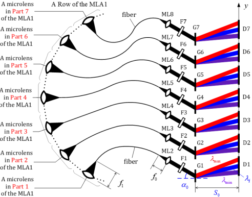
Figure 1. Optical layout of the compact 2DUFBHSIS.
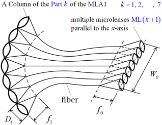
Figure 2. Schematic diagram of the positional relationship between a column of the Part k of the MLA1 and microlens array MLA(k+1).
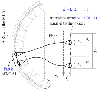
Figure 3. Schematic diagram of the positional relationship between the Part k of the MLA1 and microlens array MLA(k+1).
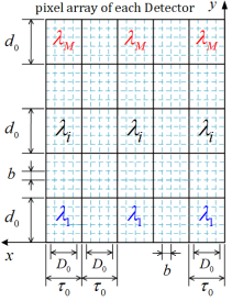
Figure 4. Schematic diagram of both spatial image distribution and spectral distribution on each detector pixel array.
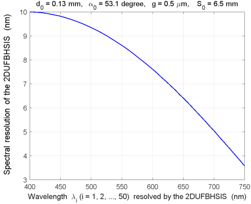
Figure 5. Spectral resolution of the 2DUFBHSIS.
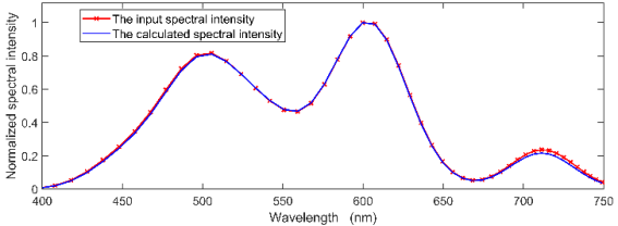
Figure 6. Comparison between the calculated spectral information and input spectral information in the wavelength range of 400 nm to 750 nm, where the input spectral information comprises only 50 wavelengths resolved by the 2DUFBHSIS, and the calculated spectral information contains only the above 50 wavelengths.
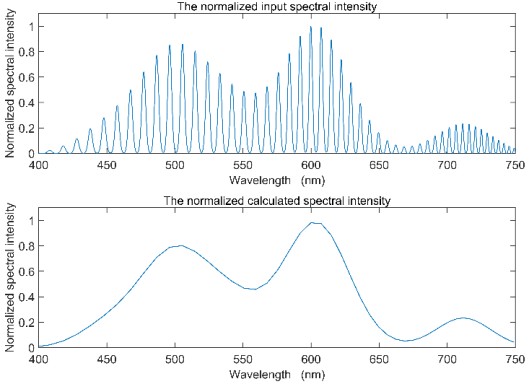
Figure 7. Comparison between the calculated spectral information and input spectral information in the wavelength range of 400 nm to 750 nm, where the input spectral information contains about 50×100 wavelengths selected from the input spectral profile shown in Figure 6, but the calculated spectral information contains only the 50 wavelengths resolved by the 2DUFBHSIS.
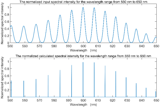
Figure 8. Comparison between the calculated spectral information and input spectral information in the wavelength range of 550 nm to 650 nm, where the input spectral information comprises about 14×100 wavelengths selected from the input spectral profile shown in Figure 6, but the calculated spectral information contains only the 14 wavelengths resolved by the 2DUFBHSIS.

Information



 Share This Article
 Twitter
 Linked In
 Facebook
 Copy
Copy Download