Research Article | | Peer-Reviewed

SRU TGTU Hydrogenation Catalyst Lifecycle Best Practices

Received: 12 June 2024     Accepted: 28 June 2024     Published: 8 July 2024
Views:       Downloads:
Abstract

This report highlights the best practices captured in the management of Tail-Gas Treatment Unit (TGTU)’s hydrogenation CoMo catalyst throughout its lifecycle, these best practices were developed based on success story in operating the TGTU, which provides technical framework to manage TGTU unit performance throughout TGTU catalyst lifecycle. The aforementioned TGTU CoMo catalyst management best practices span across the whole catalyst lifecycle, starting from cradle stage of activating/sulphiding the fresh oxide-form catalyst up to grave stage of unloading & handling the spent catalyst to a safe location. Furthermore, stressing points have been provided to record special procedure to activate catalyst’s active sites (Cobalt & Molybdenum) in a process commonly known as “sulphiding”, as well as “passivation” procedure during TGTU catalyst unloading due to the presence of pyrophoric material such as Iron Sulphide (FeS) in the TGTU converter. This developed best practices provide solid reference point for future TGTU catalyst management throughout its lifecycle. Therefore, it can be adopted and consistently applied across other TGTU-based Sulfur Recovery Unit (SRU) plants in order to maintain the optimum Sulfur Recovery Efficiency (SRE), minimize plant downtime due to catalyst replacement and prevent unwanted environmental issues such as SOx emissions).

Published in Journal of Energy, Environmental & Chemical Engineering (Volume 9, Issue 3)
DOI 10.11648/j.jeece.20240903.11
Page(s) 70-79
Creative Commons

This is an Open Access article, distributed under the terms of the Creative Commons Attribution 4.0 International License (http://creativecommons.org/licenses/by/4.0/), which permits unrestricted use, distribution and reproduction in any medium or format, provided the original work is properly cited.

Copyright

Copyright © The Author(s), 2024. Published by Science Publishing Group

Keywords

CoMo Catalyst, Sulphiding, Passivation, Catalyst Assessment, Catalyst Unloading/Loading, SRE, SRU, TGTU

1. Introduction
SRU Turnaround and Inspection it was and still a challenging scope to be performed. Either due to the production demand where the team has to bring the train to operation at soonest, or because of the hazards associated with the activities. In addition, the scope will become even harder, If the SRU was equipped with a TGTU which considered as a H2S producer by converting sulfur elements into H2S via hydrogenation catalyst. Hence, in this technical paper, the captured best practices in TGTU hydrogenation catalyst replacement will be highlighted throughout its lifetime. These best practices were developed based on hands on experience in operating the unit which provide technical framework to manage TGTU performance throughout hydrogenation catalyst lifetime.
The aforementioned hydrogenation catalyst best practices span across the whole catalyst lifetime, starting from cradle stage of activating the fresh catalyst up to grave stage of unloading & handling the spent catalyst to a safe location. Furthermore, stressing points have been provided to record special procedure to activate catalyst’s active sites (Cobalt & Molybdenum) in a process commonly known as “Sulphiding” as well as “Passivation” procedure during TGTU catalyst unloading due to the presence of pyrophoric material (FeS) in TGTU Converter. This developed best practices provide solid reference point for future hydrogenation Catalyst management throughout its lifetime. Therefore, it can be adopted and consistently applied across other TGTU-based Sulfur Recovery Unit (SRU) plants in order to maintain the Sulfur Recovery Efficiency (SRE), minimize train downtime due to catalyst replacement and prevent unwanted environmental issue (SOx emission).
2. Background and Context
In 1883 Carl Friedrich Claus proposed a reaction to convert toxic hydrogen sulfide (H2S) into valuable elemental sulfur, this patented single-step approach described in Eqn. (1) was very exothermic.
H2S+0.5 O218S8+H2O H=-187 kJmol(1)
To avoid high exothermic reaction in original Claus’s approach, in 1938 I. G. Farbenindustrie A. G. proposed a new two-steps approach Eqns. (2, 3) in which one-third of H2S in the feed burns in a controlled manner.
H2S+1.5 O2SO2+H2O H=-518 kJmol   (2)
2H2S+SO212S2+2H2O ΔH= -42 kJmol(3)
TGTU-based SRU consist of three process sections with each one providing a specific objective to meet the required overall SRE of 99.95% in SRU .
2.1. Claus Section
As Figure 1 illustrates, the Amine Acid Gas (AAG), Sour Water Acid Gas (SWAG), and acid gas recycle from TGTU section are combined and routed to Claus Main Burner (CMB). Combustion air supplied to CMB is exactly sufficient to burn one-third of H2S in the feed, the process gas then passes to Claus Main Combustion Chamber (CMCC) in which the second part of modified Claus reactions takes place at temperature above 1920 to produce Water (H2O) and Sulfur Vapor (S2) to obtain a ratio of H2S-2SO2=0 at the outlet of the 3rd sulfur condenser. The elevated temperature in CMCC is required to ensure the SRE of 60-70% at the outlet of CMCC , in addition to ensure full Benzene, Toluene, and Xylene (BTX) destruction to prevent fouling in downstream Claus catalyst .
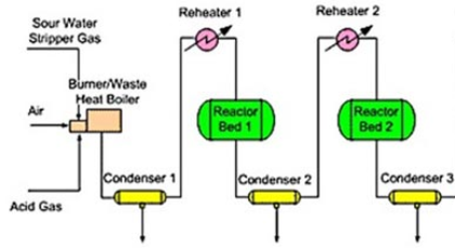
Figure 1. Claus Section Process Flow Diagram .
The hot process gas then passes to the tube bundle located in the Claus Waste Heat Boiler (C-WHB) to recover the heat generated from CMCC. Sulfur vapors are then routed to 1st Claus Condenser to condense sulfur vapor to molten sulfur, this is to shift reaction equilibrium towards the forward path . The reaming process gas goes to 1st Claus Reheater to increase temperature to meet the required operating temperature in 1st Claus Converter and increase reaction kinetics.
Activated Alumina (Al2O3) is employed in 1st Claus Converter to convert H2S to elemental sulfur, in addition to that the converter is filled with expensive, huge quantity of Titania (TiO2) catalyst to improve Carbonyl sulfide (COS) and Carbon disulfide (CS2) hydrolysis , employing Titania increases COS and CS2 hydrolysis from 65% and 30%, respectively in the first converter, to achieve conversion as high as 90% . Sulfur vapors are then routed to 2nd Claus Condenser to perform the same function mentioned earlier in 1st Claus Condenser, at the end of 1st Claus catalytic stage SRE may reach up to ~89% . The 2nd Claus catalytic stage works on the same methodology as 1st Claus catalytic stage with little variation in Alumina-to-Titania catalyst ratio, at the end of this stage SRE may reach up to ~95% .
2.2. TGTU and Incinerator Sections
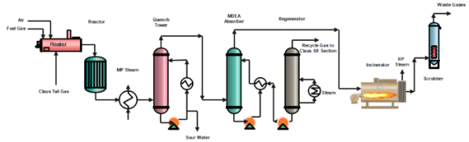
Figure 2. Process Flow Diagram (PFD) of TGTU and Incinerator Section .
Due to stringent regulation to minimize Sulfur Dioxides (SOx) emission in SRU’s stack to meet World Bank Standards of 150 mg/Nm3 of SOx (equivalent to 57 ppm) , therefore as Figure 2 illustrates, to maximize SRE from 95% up to 99.95% a third catalytic stage is utilized to convert all sulfur-containing compounds (excluding H2S) from Claus Tail Gas to H2S and recycle it back to the front of CMB in Claus Section. A hydrogenation converter followed by amine separation system ensures meeting the required SRE in the SRU.
TGTU hydrogenation converter filled with CoMo catalyst supported on Al2O3 (CoMo/Al2O3) is employed to ensure the conversion of all sulfur-containing compounds (excluding H2S) to H2S, according to reactions in Eqns. (4-8). The focus in this case report will be concentrated on this system.
Hydrogenation Reactions on CoMo Active Sites:
SO2+3H2H2S+2H2O(4)
S2+2H22H2S(5)
Hydrolysis reactions on Al2O3 support surface:
COS+H2OCO2+H2S(6)
CS2+H2OCOS+H2S(7)
CS2+2H2OCO2+H2S(8)
The effluent from TGTU hydrogenation converter routed to quench column in which all water generated in Eqns. (2-4) is condensed in the column, in addition to cooling process gas prior entering TGTU amine system. The cooled process gas enters amine absorber to counter-currently contact with an H2S-selective Methyldiethanolamine (MDEA) amine solvent to absorb H2S and allow for CO2 slip to absorber overhead in the off-gas which then routed to incinerator for safe atmospheric disposal of the reaming unrecovered H2S. Subsequently, the rich-H2S amine routed to the amine regenerator column to regenerate rich amine with the help of steam as stripping medium. Lean amine returned back to absorber, while regenerator overhead cooled-down and recycled back to the front of CMB to boost SRE up to 99.95% .
3. Discussion
As previously hinted, the hydrogenation Catalyst lifecycle spans across the catalyst Sulphiding (activation), catalyst passivation, catalyst replacement and spent catalyst handling.
3.1. TGTU Hydrogenation Catalyst Sulphiding
The active components of the hydrogenation catalyst are cobalt and molybdenum sulphides (CoS and MoS2) and the catalyst supplied to the operating facility in the oxide form (CoO, and MoO3), which will require an activation through the sulphiding process. The Sulfur for sulphiding or activation will be provided from the Claus tail gas with higher H2S concentration .
3.1.1. Chemistry of Sulphiding
The active form of the catalyst is the intimate mixture of the cobalt sulphide and the molybdenum sulphide. Also, the atmosphere must be low in oxygen (<0.1%) for proper sulphiding to occur. As in Eqn. (9), the Cobalt oxide is sulphided in a simple one-for-one exchange in which CoO reacts with H2S to form COS (as active form) and water.
CoO + H2S  CoS + H2O(9)
The sulphiding of the molybdenum oxide is more complex. The molybdenum must be reduced from the Mo (VI) oxide to Mo (IV) sulphide. To accomplish this reduction, hydrogen sulphide and hydrogen are required as in Eqn. (10).
MoO3 + 2H2S + H2  MoS2 + 3H2O(10)
Extra care must be taken to keep the catalyst from being exposed to hydrogen in the absence of hydrogen sulphide above 390°F. If this happens, the active metals on the catalyst will be reduced to the metallic state.
3.1.2. Sulphiding Process
The sulphiding process consists of the below main stages, whilst the detail sulphiding procedure which include preparation and sulphiding stage are provided in Attachment-01, with reference of Figure 3.
(i). N2 Preheating Without Ejector
This preheating step is aimed to gradually warm up the catalyst bed to 280℉ and desorb the water from the catalyst pore. Gentle warm-up with maximum rate of 30℉/hr is critical to prevent “pop-corn effect” where rapid water desorption occurs and compromising the catalyst mechanical integrity . At this stage the ejector is still offline provides once-through preheating loop. This allows a simultaneous system nitrogen purging, as oxygen present above 0.1%-vol can lead to catalyst deterioration.
(ii). N2 Preheating with Ejector
This preheating step is aimed to subsequently warm up the catalyst bed to 356°F to prepare the catalyst bed for sulphiding reaction. When this stage is started, no reactants have been added, the catalyst bed may show an exotherm for no apparent reason. This is because the tail gas catalysts are supported on high surface area Alumina. These alumina’s are desiccants and adsorb moisture from the gas stream.
The moisture is of little consequence because the wide-open pores of the catalyst allow it to freely release the moisture without the steam explosions that can break up other catalysts.
Note: the water saturated gas will give an initial, temporary temperature rise of the bed due to the absorption of the water.
(iii). Final Prerequisite Check Prior Tail Introduction
Prior to tail gas introduction which will start the sulphiding reaction, thorough check needs to be performed to ensure safe tail gas introduction. Those prerequisites check comprises the below:
1. Tail H2S of above 0.5%-vol
This to ensure sufficient H2S concentration to optimize the sulphiding reaction rate. Lower H2S content can decrease the reaction rate or half the reaction at worst case scenario. Additionally, the absent of H2S with H2 environment at elevated temperature (above 392°F) can promote unwanted reduction reaction which convert the catalyst active metal site to metallic state which subsequently sinter into larger cluster and impair catalyst activity.
2. Tail SO2 of below 200 PPM (0.02%-vol)
This to limit SO2 present in the Quench System as the hydrogenation catalyst is yet in passive form and cannot convert the SO2 to H2S. In case of excessive SO2 breakthrough, severe plugging can be expected due to wet-Claus process in the Quench System.
3. Minimum tail H2 content of 1 – 2%-vol
As the H2 is one of the reactants for sulphiding the Molybdenum active site, the H2 content need to be maintain above 1 – 2%-vol to ensure the completion of the reaction.
4. System O2 content of below 0.1%-vol
Limiting the system O2 content below 0.1 %-vol is crucial to prevent unwanted SO3 generation which can impair the mechanical integrity of catalyst alumina site which impair catalyst activity.
(iv). Tail Gas Introduction to Perform Sulphiding Process
1. Initiation
Meeting the aforementioned pre-requisites, tail gas can be gradually introduced to the converter to start the process. Simultaneously, to allow sufficient kinetic, catalyst bed need to be gently further heat-up to 410°F with maximum rate of 20°F/hr. Extra care should be taken to continuously maintain the desired H2S and H2 content whilst keeping the SO2 below 200 ppm during this step. When the bed temperature reaches 410°F, catalyst first soaking need to be performed.
2. Initial Heat Soaking
The catalyst needs to be soaked at 410°F for 8 to 12 hours to ensure reaction equilibrium at 410°F is achieved. During Sulphiding process, it is mandated to have frequent samples analyses at the Inlet and outlet of the converter to confirm the Sulphiding completion. This is can be accomplished either by temporary instrumentation can be used to provide a continuous reading or by sending samples to the central Lab. Extra care should be continuously taken to maintain the desired H2S and H2 content whilst keeping the SO2 below 200 ppm during this step to keep the reaction at optimum rate while preventing Quench System blockages issue. Moreover, H2S breakthrough typically should be observed prior heating up the catalyst bed to final soaking to prevent unwanted reduction reaction.
3. Final Heat Soaking
Subsequent soaking needs to be performed at 480°F or maximum achievable bed temperature for minimum 12 hours. This to ensure the reaction completion by boosting the reaction kinetics. Further acceptance criteria check needs to be performed to conclude the sulphiding process:
1) Similar H2S content between inlet and outlet TGTU Converter (below 10% different is acceptable)
2) Stable quench water pH of 5 – 6 without caustic injection
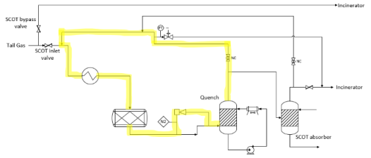
Figure 3. TGTU with Claus Tail Gas, Recycle Ejector and Steam Heater (short recycle loop).
3.2. TGTU Hydrogenation Catalyst Passivation
The TGTU is shut down for short period and long period depending on the cause of the shutdown. In the event of short shutdown, unit is temporarily isolated from SRU section and Solvent system and catalyst bed is kept at operating temperature under inert gas atmosphere for couple of days. Recirculation ejector is used for inert gas circulation. On the other hand, the shutdown for extended period is executed when entry into the converter for hydrogenation catalyst replacement or other plant’s equipment required for maintenance or inspection during turn around.
3.2.1. Passivation Process
After some time of operation, the catalyst becomes pyrophoric owing to the presence of iron sulfide (FeS). Exposure of the catalyst to air would result in uncontrolled burning of the FeS and this prevents opening of TGTU Converter for maintenance. After diverting tail gas to incinerator (TGTU Bypass), a controlled oxidation of the FeS in the converter is carried out by introducing a controlled amount of blower air into the circulating Nitrogen/Gas. This procedure is called passivation of the catalyst and carried out for two days prior to complete shutdown of TGTU. During this operation FeS is converted into non-pyrophoric iron compounds while the catalyst remains in its sulphided state.
3.2.2. Passivation Procedure
The passivation process comprises two main stages as described below.
(i). N2 Sweeping
The wet-N2 sweeping needs to be carried out for 24 hours with TGTU ejector online in order to moderate the catalyst condition prior air passivation. Ejector healthiness is important to have partially recycle process to conserve nitrogen demand.
(ii). Air Passivation
Gradually the nitrogen supply needs to be reduced and simultaneously introduce the warm passivation air supply (approx. 200°F) to the converter bed. Balancing the nitrogen and air supply particularly at the beginning of this stage is crucial to control the bed temperature. In-case the air supply is excessive, run-away oxidation can occur resulting in unwanted bed temperature spikes.
Table 1. Passivation Process Guidelines.

SN.

Activity

Throughout the passivation process, care shall be taken for the below to allow a safe and complete passivation activity:

1

Perform passivation with warm passivation air supply (approx. 200 °F) to enhance the kinetics.

2

Gradually increase the passivation air supply until maximum achievable rate is obtained to ensure sufficient turbulence for preventing dead zone.

3

Continuously balance the air flow with nitrogen flow to control the oxidation process.

The air passivation stage is undertaken until the below acceptance criteria are met:

Maximum passivation air supply (passivation air valve is fully open).

Zero nitrogen supply (N2 injection valve is fully closed).

No temperature increases (spikes) in all converter bed layers.

Temperature keeps dropping reaching ~120°F in all converter bed layers.

Uniform bed temperature profile (maximum of 5 - 10°F different between all layers).

(iii). Polishing Process
Upon acceptance criteria have been met in Section 3.2.2.2, air passivation needs to be extended for MIN additional 48 hrs. as polishing stage. This to ensure the passivation has been completed and all pyrophoric species have been safely oxidized.
Theoretically, the aforementioned passivation process can allow safe vessel entry without any bed high temperature concern. Nevertheless, in case of temperature spikes symptom persists during vessel opening, a safe catalyst unloading under N2 environment can be applied accordingly.
3.3. TGTU Hydrogenation Catalyst Replacement
It is typical for catalyst to loss activity throughout its life cycle , the full replacement of TGTU hydrogenation catalyst is needed in order to maintain catalyst activity and unit full functionality.
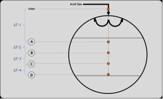
Figure 4. Converter Cross Section View with Thermocouples Distribution.
The catalyst bed’s temperature profile is used to evaluate the converter’s performance. Temperature will rise over the catalyst bed in TGTU reactor due to reaction exotherm. In order to measure the present-day catalyst activity, the temperature profiles of TGTU Hydrogenation converter need to be examined. The distribution of thermocouples among the reactors and converters is shown in Figure 4, The assessment involved the calculation of the temperature differential between the layers in order to determine the catalyst activity of each layer.
The top layer of a new catalyst is where most of the reaction takes place. The catalytic activity curves for various catalyst cases are shown in Figure 5. The graph indicates that the (A) curve is a new, active catalyst. This can serve as a guide for assessing the catalyst’s state.
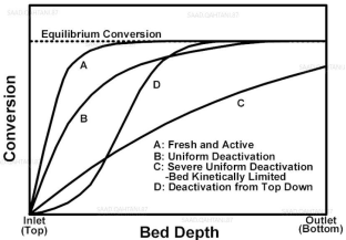
Figure 5. Catalyst Activity Profile Behaviors.
Ideally, the passivation process discussed in pervious section can allow safe vessel entry for performing catalyst unloading/loading activity. Nevertheless, in case of temperature spikes symptom persists during vessel opening, a safe catalyst unloading under N2 environment can be applied accordingly. A comprehensive evaluation and risk assessment have been conducted to develop catalyst unloading guidance under continuous nitrogen atmosphere, the approved guidance used nitrogen supply line to prevent oxygen ingress, to avoid unwanted pyrophoric flash event. During this procedure careful monitoring of critical parameters in Table 2 is required prior and during the activity.
Table 2. Unloading Critical Parameters.

Parameter

Target

LEL Reading

Zero

H2S Reading

Zero

O2 Reading

Zero

Bed Temperatures

<150 °F

N2 Supply Pressure

~20 PSIG

TGTU Hydrogenation Converter Pressure

Maintain positive pressure of 0.5-2.0 PSIG

Furthermore, after confirming the parameters in Table 2, the unloading activity started following the below sequence of events in according to the approved guidance.
Table 3. Unloading Activity Sequence of Events.

SN.

Activity

1

Contractor to install the below unloading equipment in the area:

1. Vacuum Truck

2. Catalyst Hooper

3. Dust Filter

4. Flexible Hoses

5. Breathing apparatus

6. Fire-proof certified TV box unit for the purpose of monitoring interior activity.

2

De-Torqueing and remove the top manway, only one manway allowed to be opened to minimize O2 ingress to prevent unwanted pyrophoric flash event

3

Thorough site check performed to ensure no inadvertent N2 injection to train’s vessels except for subjected TGTU Hydrogenation Converter.

4

1. The catalyst and ceramic balls vacuum-unloaded where two personnel wearing the required PPE and Supplied Air Breathing Apparatus (SABA) permitted to enter the vessel.

2. A TV box unit utilized to observe the whole process. A maximum of 30 minutes allowed for each employee to stay in the vessel before switching over with the backup crew.

5

The catalyst collected in drums, then screened, weighed, marked, labelled, and segregated.

6

SRU Process Engineers conducted a pre-inspection of the vessel, concluded with no findings (clean vessel roof, no rusty layers and no accumulated dust bellow grating).

7

SRU Process Engineers have marked the required catalyst level, carried out as per loading diagram.

8

Fresh catalyst has been loaded, SRU Process Engineers conducted visual inspection for each single layer to confirm the catalyst loading progress

3.4. TGTU Hydrogenation Catalyst Spent Catalyst Handling
Extra care needs to be taken for handling and safe disposal of the spent catalyst, to prevent unwanted pyrophoric flash event, as in Table 4:
Table 4. Spent Catalyst Handling Guidelines.

SN.

Activity

1

The spent catalyst needs to be stored and handled in drums equipped with plastic bag (to prevent O2 ingress).

2

The drums filled with water to wet/cool-down the spent catalyst and preventing unwanted pyrophoric flash event.

3

The drums allowed to be stored in T&I area not more than 24 hours.

4

The drums need to be transferred to waste handling contractor for safe disposal.

4. Conclusions and Recommendations
The detailed best practices which were highlighted in the technical paper were based on hands on experience in operating the unit which provide technical framework to manage TGTU performance throughout hydrogenation catalyst lifetime. Also, the developed best practices provide a solid reference point for future hydrogenation Catalyst management throughout its lifetime. Thus, it can be adopted and consistently applied across other TGTU-based Sulfur Recovery Unit (SRU) plants in order to maintain the Sulfur Recovery Efficiency (SRE), minimize train downtime due to catalyst replacement and prevent unwanted environmental issue (SOx emission). There are further areas of improvement could be evaluated as per below recommendations:
1) Evaluate utilizing passivation air to warm the TGTU converter beds instead of utilizing N2.
2) Evaluate replacing the hydrogenation catalyst with pre-sulphided catalyst instead of the oxide catalyst which will require activation. This is to minimize the SO2 emission.
Abbreviations

TGTU

Tail-Gas Treatment Unit

CoMo

Cobalt-Molybdenum Catalyst

FeS

Iron Sulphide

SRU

Sulfur Recovery Unit

SRE

Sulfur Recovery Efficiency

SOx

Sulfur Dioxides

AAG

Amine Acid Gas

SWAG

Sour-Water Acid Gas

CMCC

Claus Main Combustion Chamber

CMB

Claus Main Burner

BTX

Benzene, Toluene, Xylene

C-WHB

Claus Waste Heat Boiler

COS

Carbonyl Sulfide

CS2

Carbon Disulfide

LEL

Lower Explosive Limit

MDEA

Methyldiethanolamine

SABA

Supplied Air Breathing Apparatus

Acknowledgments
The authors sincerely acknowledge the support of FGP management throughout the entire developing process of this case report.
Author Contributions
Abdulrahman Musa Muabber: Data curation, Formal Analysis, Resource, Writing – original draft
Asim Jamil Alharbi: Data curation, Formal Analysis, Investigation, Writing – review & editing
Dedik Rahmat Ermawan: Conceptualization, Investigation, Supervision, Validation
Conflicts of Interest
The authors declare no conflicts of interest.
Appendix
Attachment-01
Table 5. Sulphiding Preparation.

SN. Step

1. SRU Tail gas is routed to incinerator via TGTU bypass valve.

2. Remove blinds in the system to provide the required flow paths.

3. The TGTU must be purged and air freed. This is done by injecting N2 to pressurize the system up to 0.2 to 0.3.

4. Start the water circulation in the quench column and commission the cooler controls.

5. Start the TGTU Preheater. The heat will be removed in the quench system and the gas is in recycle. Preheater setpoint (300°F), warm up rate max 30 °F/hour.

6. Start the recycle ejector to circulate gas in the system as per highlighted flow path in Figure 3.

7. Analyse the O2 content in the gas and continue N2 injection until the O2 content is < 0.1 vol%.

8. Total gas flow to the reactor should be at least 25% of the design rate to heat up the catalyst bed evenly.

9. Remain SRU Tail gas at H2S/SO2 ratio ≥ 20 to incinerator

10. Commission the analysers (Tail gas analyser, hydrogen analyser, pH analyser)

11. Caustic addition facility to quench water online with caustic pressure available up to injection valve.

Table 6. Sulphiding Procedure.

SN. Step

1. Increase steam to the TGTU reheater and warm the reactor from 300°F to maximum 356 °F at a rate of 30 °F/hour, while maintaining nitrogen filled recycle including use of the ejector.

2. Carefully close TGTU bypass valve to increase pressure of SRU tail gas to above recycle loop pressure.

3. Open TGTU inlet valve to allow tail gas into recycle flow over TGTU reactor

4. Test for the H2S content of the Reactor Inlet and analyse the H2 content with the analyser on the Quench Overhead

5. If H2 at around 2 vol%, gradually increase the temperature of the reactor bed to 410°F top bed temperature. Increase the reactor temperatures of a rate of 20°F/hour, and allow a Reactor exotherm of 50°F. If the exotherm exceeds 50°F, slowdown the heating rate by reducing the temperature from TGTU Preheater. Reduce SRU tail gas flow using TGTU inlet valve

6. Soak the bed at this temperature (410°F) for a minimum of 8 to 12 hours to ensure complete activation of the catalyst.

7. Following the soak time at 410°F, adjust Tail Gas flow to the TGTU reactor to maintain H2S, H2 content.

8. Ramp up the temperature at a rate of 20°F /hour to 480 °F and hold the temperature for a minimum of 12 hours.

9. If sufficient acid gas to the SRU is available to provide heat to the reactor, rather than closing the recycle valve, the ejector can be stopped.

10. Check if sulphiding is complete by checking for breakthrough. Breakthrough can be confirmed by an analysis showing that the TGTU reactor inlet and outlet streams have the same H2S content (+- 10% relative).)

11. Gradually reduce H2S/SO2 ratio to design ratio while ensuring H2 concentration remains 1 - 2 vol% (downstream reactor) and H2S remains > 1vol%

References
[1] Mokhatab, S., Poe, W. A., Mak, J. Y. Handbook of Natural Gas: Transmission and Processing Principles and Practices. 4th Ed. Cambridge, USA: Gulf Professional Publishing; 2019, pp. 271-305.
[2] Mohamed Fahim, Taher Al-Sahhaf, Amal Elkilani. In Acid Gas Processing and Mercaptans Removal. Fundamentals of Petroleum Refining, 1st edition. Oxford, UK: Elsevier; 2010, 377-402.
[3] Shahryar Jafarinejad. Control and treatment of sulfur compounds, specially sulfur oxides (SOx) emissions from the petroleum industry: A review. Chemistry International. 2016, 2(4), 242-253.
[4] Sulfur Recovery Experts (SRE). Sulfur Recovery Process. Available from:
[5] Ben Spooner, Farsin Derakhshan. Reducing CO2 In the Recycle Acid Gas From MDEA-Based Tail Gas Treating Units. In 2012 AIChE Spring National Meeting, Texas, USA, 2012.
[6] Bernhard Schreiner. Der Claus-Prozess. Reich an Jahren und bedeutender denn je, Chemie in Unserer Zeit. 2008, 42(6), 378-392.
[7] V. Wong, A. Sanchez, J. Flowers, T. Chow, D. Sikorski, N. Roussakis. Key Design Features for A Successful SRU Operation Implemented with Oxygen Enrichment Technology. 2010.
[8] Mansour Al-Shafei, Ahmed Al-Asseel, Abdulhadi Adab, Hasan Al-Jama, Amer Al-Tuwailib, Shouwen Shen. Deactivation Mechanism of Titania Catalyst. Journal of Materials Science Research. 2016, 5(4), 22-33.
[9] Flavio Manenti, Davide Papasidero, Giulia Bozzano, Sauro Pierucci, Eliseo Ranzi, Guido Buzzi-Ferraris. Total plant integrated optimization of sulfur recovery and steam generation for Claus processes using detailed kinetic schemes. Computer Aided Chemical Engineering. 2013, 32, 811-816.
[10] P. D. Clark, N. I. Dowling, M. Huang. Conversion of CS2 and COS over alumina and titania under Claus process conditions: reaction with H2O and SO2. Applied Catalysis B: Environmental. 2001, 31(2), 107-112.
[11] The Petro Solutions. Tail Gas Treatment in Sulfur Recovery Unit Available from:
[12] John Specht, Pat Holub. SCOT Ultra Powers Performance, Hydrocarbon Engineering. 2017, 36-41.
[13] Henrik Topsoe, Bjerne Clausen, Franklin Massoth. In Technological Aspects. Hydrotreating Catalysis: Science and Technology, 1st edition. Berlin, Germany: Springer-Verlag; 1996, Springer-Verlag, Berlin, Germany. 1-29.
[14] Stephen N. Massie. Sulfiding of Tail Gas Catalyst Proper Preparation of Tail Gas Hydrogenation Catalyst for Long and Active Life. Gas Processors Association Europe Amsterdam, The Netherlands, 2008;
[15] Reactor Resources. Sulfiding 101 An Introduction to Sulfiding of Hydrotreating Catalysts Available from:
Cite This Article
  • APA Style

    Muabber, A. M., Alharbi, A. J., Ermawan, D. R. (2024). SRU TGTU Hydrogenation Catalyst Lifecycle Best Practices. Journal of Energy, Environmental & Chemical Engineering, 9(3), 70-79. https://doi.org/10.11648/j.jeece.20240903.11

    Copy | Download

    ACS Style

    Muabber, A. M.; Alharbi, A. J.; Ermawan, D. R. SRU TGTU Hydrogenation Catalyst Lifecycle Best Practices. J. Energy Environ. Chem. Eng. 2024, 9(3), 70-79. doi: 10.11648/j.jeece.20240903.11

    Copy | Download

    AMA Style

    Muabber AM, Alharbi AJ, Ermawan DR. SRU TGTU Hydrogenation Catalyst Lifecycle Best Practices. J Energy Environ Chem Eng. 2024;9(3):70-79. doi: 10.11648/j.jeece.20240903.11

    Copy | Download

  • @article{10.11648/j.jeece.20240903.11,
      author = {Abdulrahman Musa Muabber and Asim Jamil Alharbi and Dedik Rahmat Ermawan},
      title = {SRU TGTU Hydrogenation Catalyst Lifecycle Best Practices
    },
      journal = {Journal of Energy, Environmental & Chemical Engineering},
      volume = {9},
      number = {3},
      pages = {70-79},
      doi = {10.11648/j.jeece.20240903.11},
      url = {https://doi.org/10.11648/j.jeece.20240903.11},
      eprint = {https://article.sciencepublishinggroup.com/pdf/10.11648.j.jeece.20240903.11},
      abstract = {This report highlights the best practices captured in the management of Tail-Gas Treatment Unit (TGTU)’s hydrogenation CoMo catalyst throughout its lifecycle, these best practices were developed based on success story in operating the TGTU, which provides technical framework to manage TGTU unit performance throughout TGTU catalyst lifecycle. The aforementioned TGTU CoMo catalyst management best practices span across the whole catalyst lifecycle, starting from cradle stage of activating/sulphiding the fresh oxide-form catalyst up to grave stage of unloading & handling the spent catalyst to a safe location. Furthermore, stressing points have been provided to record special procedure to activate catalyst’s active sites (Cobalt & Molybdenum) in a process commonly known as “sulphiding”, as well as “passivation” procedure during TGTU catalyst unloading due to the presence of pyrophoric material such as Iron Sulphide (FeS) in the TGTU converter. This developed best practices provide solid reference point for future TGTU catalyst management throughout its lifecycle. Therefore, it can be adopted and consistently applied across other TGTU-based Sulfur Recovery Unit (SRU) plants in order to maintain the optimum Sulfur Recovery Efficiency (SRE), minimize plant downtime due to catalyst replacement and prevent unwanted environmental issues such as SOx emissions).
    },
     year = {2024}
    }
    

    Copy | Download

  • TY  - JOUR
    T1  - SRU TGTU Hydrogenation Catalyst Lifecycle Best Practices
    
    AU  - Abdulrahman Musa Muabber
    AU  - Asim Jamil Alharbi
    AU  - Dedik Rahmat Ermawan
    Y1  - 2024/07/08
    PY  - 2024
    N1  - https://doi.org/10.11648/j.jeece.20240903.11
    DO  - 10.11648/j.jeece.20240903.11
    T2  - Journal of Energy, Environmental & Chemical Engineering
    JF  - Journal of Energy, Environmental & Chemical Engineering
    JO  - Journal of Energy, Environmental & Chemical Engineering
    SP  - 70
    EP  - 79
    PB  - Science Publishing Group
    SN  - 2637-434X
    UR  - https://doi.org/10.11648/j.jeece.20240903.11
    AB  - This report highlights the best practices captured in the management of Tail-Gas Treatment Unit (TGTU)’s hydrogenation CoMo catalyst throughout its lifecycle, these best practices were developed based on success story in operating the TGTU, which provides technical framework to manage TGTU unit performance throughout TGTU catalyst lifecycle. The aforementioned TGTU CoMo catalyst management best practices span across the whole catalyst lifecycle, starting from cradle stage of activating/sulphiding the fresh oxide-form catalyst up to grave stage of unloading & handling the spent catalyst to a safe location. Furthermore, stressing points have been provided to record special procedure to activate catalyst’s active sites (Cobalt & Molybdenum) in a process commonly known as “sulphiding”, as well as “passivation” procedure during TGTU catalyst unloading due to the presence of pyrophoric material such as Iron Sulphide (FeS) in the TGTU converter. This developed best practices provide solid reference point for future TGTU catalyst management throughout its lifecycle. Therefore, it can be adopted and consistently applied across other TGTU-based Sulfur Recovery Unit (SRU) plants in order to maintain the optimum Sulfur Recovery Efficiency (SRE), minimize plant downtime due to catalyst replacement and prevent unwanted environmental issues such as SOx emissions).
    
    VL  - 9
    IS  - 3
    ER  - 

    Copy | Download

Author Information
  • Fadhili Gas Plant Department, Saudi Aramco, Fadhili, Saudi Arabia

    Biography: Abdulrahman Musa Muabber is a Natural Gas Process Engineer works with Saudi Aramco in Jafurah Gas Plant (JFGP) and assigned to Fadhili Gas Plant (FGP)’s Sulfur Recovery Unit (SRU) and Tail-Gas Treatment Unit (TGTU). He has also received specialized training as a Crude Distillation (CDU) & Hydroprocessing (HCK) Process Engineer, in addition to Power & RO Desalination Operations Engineer. Abdulrahman has graduated from Jazan University in 2023 with BSc in Chemical Engineering and First-Class Honor Degree.

    Research Fields: Homogenous Catalytic Reactions, Oil & Gas (O&G) Industry, Sulfur Recovery Unit (SRU), Tail-Gas Treatment Unit (TGTU), Amine Systems

  • Fadhili Gas Plant Department, Saudi Aramco, Fadhili, Saudi Arabia

    Biography: Asim Jamil Alharbi is a Loos Prevention Engineer with a Mechanical Engineering background graduated from King Fahd University of Petroleum & Minerals (KFUPM) with Second-Class Honor Degree. He is also a certified Mechanical Engineer by NCEES. Moreover, he worked in different operating facilities as a Process Engineer mainly at Ras Tanura Refinery (RTR) supporting utilities and product movement division and at Fadhili Gas Plant (FGP) supporting Gas Inlet and Sulfur Recovery Units. Also, he had an intense hand on experience as maintenance and Reliability engineer at Abqaiq Plant (ABQ).

    Research Fields: Oil & Gas (O&G) Industry, Sulfur Recovery Unit (SRU), Health and Safety, Process Safety, Loss Prevention

  • Fadhili Gas Plant Department, Saudi Aramco, Fadhili, Saudi Arabia

    Biography: Dedik Rahmat Ermawan is Process Engineer with 15 years of experience in world-wide Gas Processing and LNG industry. He has graduated with BSc in Chemical Engineering from Gadjah Mada University (UGM) and post graduate degree from University of Manchester with MSc in Advance Process Design and Integration. He has completed project and operation engineering cycle with numerous demonstrable technical competencies. Currently he is working with Saudi Aramco in Fadhili Gas Plant (FGP) providing technical support for 2.5 BSCFD Gas Processing and Sulphur Recovery Complex.

    Research Fields: Sulfur Recovery Unit (SRU), LNG Technology, Dehydration Unit, Gas Sweetening Unit, Fractionation Process, Refrigeration Technology