Abstract
The portal frame, as an innovative subway protection structure, primarily serves the development of underground spaces above shield tunneling for subways. It comprises foundation piles along both sides of the tunnel and a transition thick plate. When the transfer thick plate sustains loads at its midspan, deformation occurs, interacting with the underlying soil to generate additional stresses, thereby potentially impacting the subway tunnel beneath negatively. This study, anchored in the real-case scenario of Qianhai Exchange Square, employs finite element analysis to investigate the interaction mechanisms between the transfer thick plate under midspan loading and soils of varying properties. Findings revealed a characteristic distribution pattern of additional stresses in the soil—smaller at the edges and larger at the center. Furthermore, under equal loading conditions, there's a positive correlation between soil stiffness and induced additional stress, while an inverse relationship exists with the vertical deformation of the transfer thick plate. In response to this issue, the paper innovatively proposes embedding a cushioning and isolation layer under the transfer thick plate. Based on the results of full-scale tunnel tests carried out during the early stages of the project, and by employing high-precision finite element simulations, the bearing capacity of the tunnel was determined. This analysis, in turn, informed the formulation of selection principles for the cushioning and isolation materials in a feedback manner. Computational verifications showed that appropriately designing the cushioning and isolation layer can significantly reduce additional stresses in the foundation soil, thereby effectively alleviating the impact of concentrated upper loads on the shield tunnel.
Keywords
Subway, Portal Frame, Experimental Study, Numerical Calculation, Isolation Material, Over-Crossing Shield Tunnel
1. Introduction
With the continuous development of China's economy, the density of urban rail transit in prosperous city districts has escalated, thereby compounding the challenges in developing underground spaces within areas where such transit infrastructure is already established. In recent years, there has been a rise in instances where underground space development closely adjoins existing rail transit facilities, including situations where the new construction is immediately adjacent, overhead, or diagonally intersecting with the transit infrastructure. Among these, the technical complexities surrounding the development of underground spaces above shield-driven subway tunnels pose particularly prominent issues. Prior to initiating such developments above subway shield tunnels, several factors must be meticulously considered:
1) Condition of the Existing Tunnel: After years of operation, shield tunnels may have incurred some damage due to changes in the surrounding environment, necessitating an assessment of their health status and load-bearing capacity.
2) Control of Construction Disturbance for Closely Adjacent Shield Tunnel Segments with Pile Driving: Shield tunnels, composed of multiple pipe segments assembled together, exhibit relatively low overall stiffness. Stress relief or vibrations during pile driving could exert adverse impacts on the tunnel integrity.
3) Impact of Excavation on the Lower Tunnel from Foundation Pit: Excavation of soil directly above the tunnel can lead to stress relief in the soil mass, potentially causing the tunnel to uplift, which in turn threatens the safety of subway operations. These considerations highlight the intricate balance required between urban expansion and infrastructure preservation in the quest for efficient utilization of increasingly scarce urban subterranean space.
As the number of cases involving structures constructed above subway shield tunnels increases domestically, technology for protecting these subterranean structures during overhead construction has emerged as a focal point within the engineering community. Yan Jing
analyzed various technical issues concerning the construction of foundation pits above shield tunnels, pointing out deficiencies in current protection standards that fail to account for the deformation history and unique characteristics of each tunnel. Wen SuoLin
| [3] | Wen Sulin. Control Techniques for Open Excavation Construction of Foundation Pit Crossing Operative Metro Tunnels at Close Proximity [C]. //Collected Papers of the 2010 Academic Annual Conference of the Geotechnical Engineering Branch of the Architectural Society of China. 2010: 451-454. |
[3]
reinforced the soil above the tunnel section using cement-soil mixed piles, while adopting the stripe-drawing method to reinforce the soil above the tunnel. Chen Juan et al.
| [4] | Chen Juan, Shen Bihui, Peng Jiangqiang. Analysis of Protection Measures for Foundation Pits Spanning Across Subway Interval Tunnels [C]. //Proceedings of the 2014 China Tunnel and Underground Engineering Conference (CTUC) & the 18th Annual Conference of the Tunnelling and Underground Works Division of the China Civil Engineering Society. 2014: 328-332. |
[4]
employed portal-like reinforcement for the tunnel section and utilized the stripe-drawing excavation method for the soil above, with case studies confirming the effectiveness of this approach in controlling tunnel deformation. Guo Jun
and others implemented large-scale excavation unloading above the subway, summarizing multiple construction control methods such as small shaft skip excavation, portal frames, and isolation layers for subway protection. He Xiaolong et al.
, based on data from a case involving a structure constructed above a subway tunnel, concluded that the uplifting of the subway tunnel is negatively correlated with the distance from the center of the foundation pit. Tian Shuai
, through three-dimensional finite element analysis, simulated an overhead subway shield tunnel scenario and proposed that for small-sized foundation pits (with depth and width not exceeding 10m), base reinforcement combined with stripe-drawing construction can ensure the operational safety of the subway tunnel. Currently, research on overhead subway shield tunnels primarily focuses on the impact of upper foundation pit excavation on the tunnels, while studies on the effects of subsequent building loads are relatively scarce.
This paper targets the subway protection scheme employing portal frameworks, investigating the interaction between the framework and soil under the action of mid-span loads from the superstructure. It further proposes conditions for implementing isolation layers and addresses the selection of materials for such layers. The article summarizes the methodologies and problem-solving approaches employed in this type of subway protection work.
2. Scheme for Protecting Subway Tunnels Using Portal Frame Structures
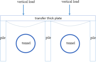
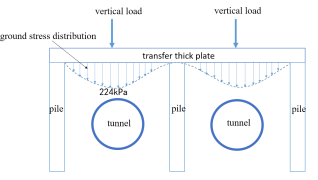
The portal frame structure comprises two main components: vertical foundation piles and a transfer thick plate, as illustrated in
Figure 1. To ensure the safety of the subway shield tunnel, foundation piles on both sides of the tunnel are typically constructed using full casing methods to minimize soil stress release during pile drilling operations. The transfer thick plate is usually installed alongside block excavation of the soil, commonly executed through either strip excavation or small shaft skip chamber methods. Once the portal frame structure is in place, it imposes a certain degree of constraint on the tunnel from above and on its sides, effectively controlling uplift and lateral displacement during soil excavation and isolating external influences during the later phase of upper building construction. This structure enables the load systems of the tunnel and external building structures to operate independently, thereby reducing mutual impacts.
The design of the in the portal frame structure is closely related to the diameter and spacing of the tunnels. As the distance between tunnels increases, so does the span of the transfer thick plate. When the plate span reaches a certain magnitude, it undergoes deformation under mid-span loading, interacting with the underlying soil and generating additional foundation stresses. These additional stresses have the potential to impose extra loads on the tunnel structure, necessitating an analysis of their distribution characteristics and the extent of their impact.
Figure 1. Schematic diagram of subway tunnel protection using portal frame.
3. Analysis of Interaction Between the Transfer Thick Plate and Foundation Soil
3.1. Case Overview
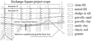
To investigate the interaction between the thick transfer plate of an overhead shield tunnel portal frame under vertical loads from the building structure and the foundation soil, the case of the Shenzhen Qianhai Exchange Square (abbreviated as: Exchange Square) subway protection is introduced. In this case, the outer diameter of the shield tunnel is 6000mm, with a wall thickness of 300mm, assembled using a staggered joint method. The stratigraphy of the site, from top to bottom, consists of artificial fill, silty clay, alluvial silty clay, granite residual soil, and weathered granite, as shown in
Figure 2.
Figure 2. Longitudinal geological section of shield tunnel.
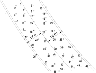
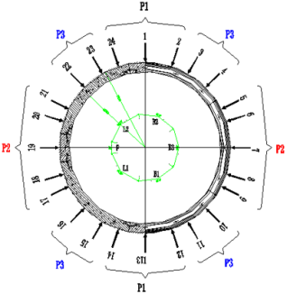
Figure 3. Diagram of load application points and numbering on the top of the subway.
The project features three levels of basement constructed alongside both sides of the subway, with one to two levels of basement built directly above the shield tunnel. Excavation depths for the foundation pits range approximately from 7 to 11 meters. To ensure the safety of the subway's shield tunnel, a portal frame structure has been adopted, whose sectional construction is depicted in
Figure 1. The transfer plate spans about 18 meters in a single bay and has a thickness of 1.3 meters. Several structural columns are positioned atop the thick plate, and the detailed plan layout of these column positions is illustrated in
Figure 3. There are 47 points of vertical loads generated by the structural columns, with specific values for both permanent loads and live loads outlined in
Table 1.
Table 1. List of Load Sequences and Values for the Building (Units: kN).
No. | Dead Load | Live Load | No. | Dead Load | Live Load |
1 | -4373 | -999 | 25 | -3252.8 | -753 |
2 | -3096 | -935 | 26 | -2150 | -566.3 |
3 | -7355 | -1926 | 27 | -2637.9 | -659 |
4 | -4512 | -1075 | 28 | -3617 | -869.1 |
5 | -5830 | -1478 | 29 | -7924 | -1579 |
6 | -7626 | -2157 | 30 | -5575 | -1240 |
7 | -4963 | -949 | 31 | -2588 | -749.1 |
8 | -4487 | -960 | 32 | -8380 | -1431 |
9 | -4901 | -1272 | 33 | -4918.5 | -1008 |
10 | -9021.3 | -2408 | 34 | -6380.5 | -1207 |
11 | -2862.6 | -573 | 35 | -7597 | -1718 |
12 | -4743 | -1014 | 36 | -7988 | -1407 |
13 | -6416 | -1633 | 37 | -8083.1 | -1389 |
14 | -1485 | -413 | 38 | -5413.4 | -1502 |
15 | -4550 | -923 | 39 | -6161 | -1518 |
16 | -3716 | -735 | 40 | -12733 | -1902 |
17 | -1690 | -589.5 | 41 | -5823 | -978 |
18 | -3230 | -994 | 42 | -5286 | -1128 |
19 | -3729.5 | -924 | 43 | -5916 | -1272 |
20 | -8116 | -1143 | 44 | -8137 | -1978 |
21 | -1827 | -569 | 45 | -4863 | -1311.8 |
22 | -1221 | -444 | 46 | -6967 | -1196 |
23 | -3640 | -1003 | 47 | -8135 | -2040 |
24 | -5781.3 | -1091 | | | |
3.2. Analysis of Resistance of Foundation Soils with Different Stiffness
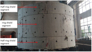
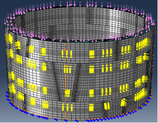
The Exchange Square project commenced in 2015; however, the subway shield tunnel lying beneath it underwent multiple changes in external engineering conditions from 2008 to 2015, leading to a non-optimal or suboptimal state of some sections of the tunnel. The internal diameter of parts of the tunnel had increased from the initial 5400mm to 5470mm or more. Given the unique characteristics of this project, a multitude of full-scale shield tunnel experiments were conducted to investigate the existing condition and bearing capacity of the shield tunnel, with experimental photographs illustrated in
Figure 4. The research findings revealed that the majority of the tunnels were in an elastic-plastic state, and the process of excavating and unloading soil from the Exchange Square foundation pit could not fully rectify the portions where horizontal convergence values exceeded the standards. Furthermore, with the subsequent increase in vertical loads, there remained a possibility of adverse effects on the shield tunnel. Consequently, the project adopted a gate-type frame structure as the subway protection scheme.
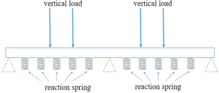
Under the action of vertical loads at the span, the transfer plate will experience a certain degree of deformation and, in turn, compress the underlying soil, generating additional stresses. The magnitude of these stresses is associated with both the amount of deformation and the deformation modulus of the soil. To streamline the calculation model, the pile foundations at the two ends and the center of the bottom of the transfer plate are approximated as hinged supports, while the soil beneath the span is simplified into reaction springs. This simplified model is depicted in
Figure 5.
Figure 4. Photos of shield test site.
Figure 5. Schematic diagram of calculation and analysis model.
To investigate the interaction between the transfer plate and foundation soil under various stiffness conditions, refer to the value of the vertical foundation bed coefficient K
V of foundation soil in the foundation pit engineering manual
| [10] | Liu Jianhang, Hou Xueyuan. Analysis of Internal Forces in Retaining Structures. In: Manual of Foundation Pit Engineering, 1st Edition. Beijing: China Architecture & Building Press; 1997, pp. 139-144. |
[10]
, as shown in
Table 2.
Table 2. List of vertical subsoil subbed coefficients KV.
No. | Soil Layer | KV (kN/m3) | Calculated Value (kN/m3) |
1# | Muddy clay | 5000~10000 | 5000 |
2# | Soft plastic general clay | 10000~20000 | 10000 |
3# | Plastic general clay | 20000~40000 | 20000 |
4# | Hard molded general clay | 40000~100000 | 40000 |
5# | Dense old clay | 50000~150000 | 50000 |
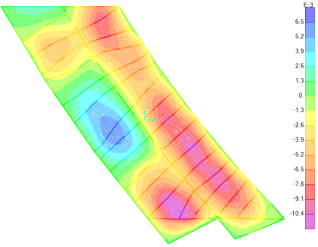
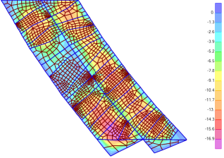
Figure 6. Vertical Deformation Diagram of the Structure Under Soil Layer 1 Conditions (Unit: m).
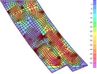
Figure 7. Foundation Stress Distribution Diagram under Soil Layer 1 Conditions (Unit: kPa).
By establishing the structural calculation model, deformation diagrams of the transfer thick plate under various soil layer conditions and stress distribution diagrams of the foundation soil are obtained. Due to space limitations, only the deformation diagram of the transfer plate under condition of Soil Layer 1 and the additional stress distribution diagram of the foundation are presented, as shown in
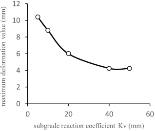
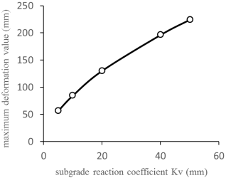
Figures 6 and 7 respectively. The additional stress distribution exhibits a parabolic shape with higher values in the middle and tapering off towards both ends. The deformation trends of the transfer plates under different soil layers remain fundamentally consistent; the maximum deformation values decrease as the K
V value of the foundation soil increases. Conversely, the maximum values of additional stress in the foundation increase with an increase in the K
V value of the soil, as illustrated in
Figures 8-9.
According to
Figure 9, there are significant differences in the additional stresses generated by various soil layers. When the foundation soil is of Layer 5, the maximum additional stress reaches 224 kPa (equivalent to a soil load of 12m), exceeding the original overburden gravity load. Based on the research findings in Reference
| [11] | Wang Kangren, Pang Xiaozhao, Liu Shuya, et al. Research on Load-bearing Performance and Structural Safety Indices of Segmented Shield Tunnels with Offset Joints under Complex Loading Conditions [J]. Modern Tunnelling Technology, 2018, 55(S2): 588-598. https://doi.org/10.13807/j.cnki.mtt.2018.S2.076 |
| [12] | Liu Xuezeng, Cai Guangyuan, Yang Fan, et al. Structural Load-Carrying Performance and Deformation Control Indicators of Shield Tunnel with Mosaic Assembled in Fractured Surrounding Rock [J]. China Journal of Highway and Transport, 2017, 30(8): 9-15. https://doi.org/10.3969/j.issn.1001-7372.2017.08.006 |
| [13] | Wang Shimin, Shen Xingzhu, He Xiangfan, et al. Experimental Study on Force and Failure Mode of Shield Tunnel Lining under Different Assembly Methods [J]. Journal of Civil Engineering, 2017, 50(6): 11-18. https://doi.org/CNKI:SUN:TMGC.0.2017-06-013 |
| [14] | Liu Zhao. Experimental and Simulation Analysis of the Deformation Performance of Shield Tunnel Lining with Mosaic Assembly under Complex Working Conditions [D]. China Academy of Railway Science, 2017. |
| [15] | Fan Yiming, Li Bo, Liu Bo. Analysis of Force and Deformation of Extra-Large Diameter Shield Tunnel Lining Considering Different Segment Assembly Methods [J]. Journal of Anhui University of Architecture, 2021. https://doi.org/10.11921/j.issn.2095-8382.20210103 |
[11-15]
, the differential value between the vertical pressure P1 at the top of the shield tunnel and the constraining force P2 at its sides is a crucial parameter for the safety of the shield tunnel; a larger value indicates a higher risk of tunnel failure. Furthermore, when the shield tunnel is in an elastic-plastic state, reloading the same load after unloading may lead to the formation of new cracks or an additional increase in horizontal convergence values. Given that the additional stresses resulting from the interaction between the transfer plate and the foundation soil exhibit a pattern of high in the middle and low at both ends (as shown in
Figure 10), their transmission to the vertical pressure P1 at the tunnel's top significantly increases, whereas the increase in the side constraining force P2 is not as pronounced. This tendency exacerbates tunnel deformation in an unfavorable direction.
Figure 8. Diagram showing the relationship between the maximum deformation values of the converted thick plate and the subgrade reaction coefficient under the same loading condition.
Figure 9. Chart illustrating the relationship between the maximum additional stress and the subgrade reaction coefficient under identical loading conditions.
Figure 10. Diagram showing the distribution of foundation stresses when the foundation consists of Soil Layer 5.
4. Analysis of Bearing Capacity of Shield Tunnel
The long-term operation of shield tunnels may lead to a reduction in their bearing capacity due to changes in external conditions, thus necessitating an analysis and evaluation of their current bearing capacity. In the Exchange Square project, certain shield tunnels are in a suboptimal or unhealthy state, with a horizontal convergence value of 70mm serving as the threshold for reinforcing tunnels with steel rings. Therefore, unreinforced shield tunnels with horizontal convergence values ranging from 60 to 70mm are the primary focus of subway protection. The safety control index for horizontal convergence deformation values for these shield tunnel rings is set at +1.5mm, +2mm, and +3mm corresponding to three warning levels. This study selects a group of shield tunnels with a horizontal convergence value of 64.3mm as the subject for bearing capacity analysis.
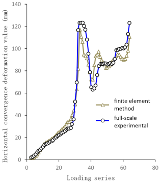
The previous full-size model test results were used to establish a three-dimensional fine-grained finite element shield analysis model of two-ring staggered assembly, as depicted in
Figure 11. The load mode and boundary conditions of this model are essentially consistent with the full-size test. The tunnel confining pressure loads are categorized into three groups: P1 (top and bottom load), P2 (waist load) and P3 (shoulder load), as illustrated in
Figure 12. By comparing the results (
Figure 13), it is confirmed that the finite element model can effectively simulate the deformation history of the test segment, and the parameters are reasonable for application in calculating and analyzing other working conditions.
Figure 11. Three-dimensional refined finite element analysis model.
Figure 12. Loading distribution diagram for shield tunnel computation and analysis.
Figure 13. Comparison chart of full-scale experimental and finite element model horizontal convergence deformation curves.
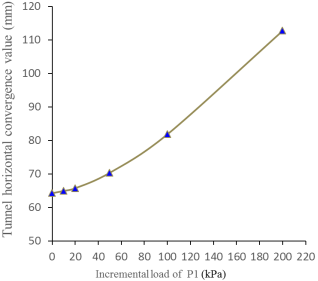
Figure 14. Response values of tunnel horizontal convergence under different incremental load conditions.
The finite element calculation procedure is as follows: First, the deformation of the shield tunnel in the computational model is adjusted to match the current state of the shield tunnel, where the horizontal convergence value is 64.3mm. Secondly, load set P1 is incrementally increased by 10kPa, 20kPa, 50kPa, 100kPa, and 200kPa respectively. Through computation, the responses in terms of tunnel horizontal convergence under different loading conditions are obtained, as depicted in
Figure 14. Consequently, it is derived that additional loads corresponding to tunnel horizontal convergence increments of +1.5mm, +2.0mm, and +3.0mm are respectively 20.2kPa, 24kPa, and 32kPa. To ensure tunnel safety, the maximum additional load on the tunnel roof is controlled at 20.2kPa.
5. Analysis of the Interaction Between the Isolation Layer and the Transfer Thick Plate
According to
Figure 9, the additional stresses transmitted from the transfer thick plate to various types of foundation soils all exceed 20.2 kPa. Given the relatively close proximity of the transfer thick plate to the tunnel, the diffusion of the additional stress is not pronounced. Consequently, the direct additional load applied to the tunnel may surpass 20.2 kPa (corresponding to the allowable increment in tunnel horizontal convergence +1.5 mm), failing to meet the bearing capacity control criterion.
To mitigate the adverse effects of deformation caused by the transfer thick plate, it is essential to install an interlayer of cushion and isolation between the plate and the foundation soil. With the principle of safeguarding the safety of shield tunneling in mind, the cushion and isolation layer must adhere to certain stiffness requirements, with key considerations as follows: Firstly, it must ensure no cave-in occurs during the concrete pouring process of the transfer thick plate, preventing excessive compression deformation that could otherwise render the layer unable to function effectively as a cushion and isolator later on. Secondly, following the formation of the portal frame structure, if the stiffness of the cushion and isolation layer is too low, the structure will fail to efficiently restrain the tunnel's floating deformation.
In the Exchange Square project, the thickness of the transfer plate is 1.3m. In order to ensure the flatness of the plate, a 0.1m thick plain concrete cushion layer is set at its bottom, and the cushion and isolation layer is arranged below the cushion layer. When the construction of the transfer plate is completed, the cushion and isolation layer has borne the self-weight load of 37.5kPa of the transfer plate and plain concrete cushion above. When analyzing the interaction between the transfer plate and the cushion and isolation layer, the pre-loading problem of 37.5kPa of the previous self-weight load is considered.
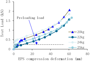
According to the safety principle of shield tunnel, EPS material was selected for cushion and isolation layer, and mechanical tests were carried out on EPS with the weight of 20kg/m³, 22kg/m³, 24kg/m³ and 25kg/m³ respectively. The test sample size is a cube of 100mm×100mm×100mm. Load displacement curves of various EPS materials were obtained through experiments, as shown in
Figure 15. The project selected EPS of 24kg/m³.
Figure 15. Load displacement curves of various EPS materials.
Through calculation, the maximum value of additional stress after the cushion and isolation layer is set is 16.9kPa, far less than the additional stress of the unbuffered isolation layer, and also meets the limit value of 20.2kPa, as shown in
Figure 16. Therefore, the EPS material can effectively cushion and isolate the additional stress caused by the upper mid-span load on the foundation, and effectively protect the subway shield tunnel.
Figure 16. Stress distribution diagram of cushion and isolation layer (unit: kPa).
6. Conclusions
As a novel form of subway protection structure, the portal frame is extensively utilized in the subterranean development of subway shield tunnels. Drawing from the case study of Qianhai Exchange Square, this paper investigates the interaction between the thick transfer plate and various foundation soils under mid-span loading, analyzes the horizontal convergence deformation response of shield tunnels under different load conditions during sub-health states, and discusses the selection principle of cushion and isolation materials based on their bearing capacity. The following conclusions are drawn:
(1) Under mid-span loading, the thick transfer plate will undergo certain deformation, with its deformation negatively correlated to the stiffness of the foundation soil. Compressed foundation soil will generate additional stress, which is greater at the middle span and smaller at both ends.
(2) The bearing capacity of shield tunnels protected by portal frames should be comprehensively considered within their stress history conditions and determined according to their individual circumstances.
(3) The selection of cushion and isolation materials should fully consider the load impact from the thick transfer plate during construction while ensuring that it meets construction and operational requirements.
(4) Through calculation and verification, it has been demonstrated that setting a cushion and isolation layer can effectively reduce additional stress on foundation soil, thereby significantly mitigating impacts from upper mid-span loading on shield tunnels.
Acknowledgments
Special thanks to Shenzhen Qianhai Investment Holding for their support in project management techniques.
Author Contributions
Gu Wentian: Conceptualization, Data curation
Zhao Qijia: Resources, Methodology
Lu Yuan: Formal Analysis, Investigation, Visualization
Funding
This work is supported by China Academy of Railway Sciences Corporation Limited Institute of Funder (Grant No. 2021YJ016).
Data Availability Statement
The data is available from the corresponding author upon reasonable request.
Conflicts of Interest
The authors declare no conflicts of interest.
References
| [1] |
Yan Jing. Several Technical Issues and Engineering Experiences concerning the Excavation Pit Crossing Shield Tunnel [J]. Municipal Engineering Technology, 2018, 36(6): 177-182.
https://doi.org/10.3969/j.issn.1009-7767.2018.06.055
|
| [2] |
Wei Gang. Measurement and Analysis of the Influence of Excavation Pit on the Existing Shield Tunnel Below [J]. Rock and Soil Mechanics, 2013, 34(5): 8-14.
https://doi.org/10.13393/j.cnki.issn.1672-948X.2013.05.008
|
| [3] |
Wen Sulin. Control Techniques for Open Excavation Construction of Foundation Pit Crossing Operative Metro Tunnels at Close Proximity [C]. //Collected Papers of the 2010 Academic Annual Conference of the Geotechnical Engineering Branch of the Architectural Society of China. 2010: 451-454.
|
| [4] |
Chen Juan, Shen Bihui, Peng Jiangqiang. Analysis of Protection Measures for Foundation Pits Spanning Across Subway Interval Tunnels [C]. //Proceedings of the 2014 China Tunnel and Underground Engineering Conference (CTUC) & the 18th Annual Conference of the Tunnelling and Underground Works Division of the China Civil Engineering Society. 2014: 328-332.
|
| [5] |
Guo Jun, Wen Jiaming, Gu Wentian, et al. Underground Space Development Technology above Shield Tunnels [J]. Railway Construction, 2020, 60(7): 64-68.
https://doi.org/10.3969/j.issn.1003-1995.2020.07.16
|
| [6] |
Cheng XZ. Research on Deformation Control of Subway Shield Tunnel Passing Under Existing Railway [J]. Modern Urban Rail Transit, 2012, 6(6): 4.
https://doi.org/10.3969/j.issn.1672-7533.2012.06.014
|
| [7] |
He Xiaolong, Dong Haowei, Chen Yanqing, et al. Monitoring and Numerical Analysis of the Deformation Effects of Excavation above Subway Tunnels on the Interval Tunnels [J]. Journal of Hydraulic Engineering and Architecture, 2019, 17(4): 39-44.
https://doi.org/10.3969/j.issn.1672-1144.2019.04.007
|
| [8] |
Gao Q, Yu WL. Analysis of the Impact of Municipal Tunnel Excavation Pit on the Existing Subway Shield Tunnel [J]. Tunnel Construction, 2014, 34(4): 7-12.
https://doi.org/10.3973/j.issn.1672-741X.2014.04.004
|
| [9] |
Tian Shuai. Research on Protection Scheme for Foundation Pit Crossing Operational Subway Tunnels under Complex Conditions [J]. Tunnel Construction (English Edition), 2020, 40(S2): 196-203.
https://doi.org/10.3973/j.issn.2096-4498.2020.S2.025
|
| [10] |
Liu Jianhang, Hou Xueyuan. Analysis of Internal Forces in Retaining Structures. In: Manual of Foundation Pit Engineering, 1st Edition. Beijing: China Architecture & Building Press; 1997, pp. 139-144.
|
| [11] |
Wang Kangren, Pang Xiaozhao, Liu Shuya, et al. Research on Load-bearing Performance and Structural Safety Indices of Segmented Shield Tunnels with Offset Joints under Complex Loading Conditions [J]. Modern Tunnelling Technology, 2018, 55(S2): 588-598.
https://doi.org/10.13807/j.cnki.mtt.2018.S2.076
|
| [12] |
Liu Xuezeng, Cai Guangyuan, Yang Fan, et al. Structural Load-Carrying Performance and Deformation Control Indicators of Shield Tunnel with Mosaic Assembled in Fractured Surrounding Rock [J]. China Journal of Highway and Transport, 2017, 30(8): 9-15.
https://doi.org/10.3969/j.issn.1001-7372.2017.08.006
|
| [13] |
Wang Shimin, Shen Xingzhu, He Xiangfan, et al. Experimental Study on Force and Failure Mode of Shield Tunnel Lining under Different Assembly Methods [J]. Journal of Civil Engineering, 2017, 50(6): 11-18.
https://doi.org/CNKI:SUN:TMGC.0.2017-06-013
|
| [14] |
Liu Zhao. Experimental and Simulation Analysis of the Deformation Performance of Shield Tunnel Lining with Mosaic Assembly under Complex Working Conditions [D]. China Academy of Railway Science, 2017.
|
| [15] |
Fan Yiming, Li Bo, Liu Bo. Analysis of Force and Deformation of Extra-Large Diameter Shield Tunnel Lining Considering Different Segment Assembly Methods [J]. Journal of Anhui University of Architecture, 2021.
https://doi.org/10.11921/j.issn.2095-8382.20210103
|
Cite This Article
-
APA Style
Wentian, G., Qijia, Z., Yuan, L. (2024). Research on the Application of Cushion and Isolation Materials in Protecting the over Shield Tunnel. Journal of Civil, Construction and Environmental Engineering, 9(4), 122-130. https://doi.org/10.11648/j.jccee.20240904.14
 Copy
|
Copy
|
 Download
ACS Style
Wentian, G.; Qijia, Z.; Yuan, L. Research on the Application of Cushion and Isolation Materials in Protecting the over Shield Tunnel. J. Civ. Constr. Environ. Eng. 2024, 9(4), 122-130. doi: 10.11648/j.jccee.20240904.14
Copy
|
Download
AMA Style
Wentian G, Qijia Z, Yuan L. Research on the Application of Cushion and Isolation Materials in Protecting the over Shield Tunnel. J Civ Constr Environ Eng. 2024;9(4):122-130. doi: 10.11648/j.jccee.20240904.14
Copy
|
Download
-
@article{10.11648/j.jccee.20240904.14,
  author = {Gu Wentian and Zhao Qijia and Lu Yuan},
  title = {Research on the Application of Cushion and Isolation Materials in Protecting the over Shield Tunnel
},
  journal = {Journal of Civil, Construction and Environmental Engineering},
  volume = {9},
  number = {4},
  pages = {122-130},
  doi = {10.11648/j.jccee.20240904.14},
  url = {https://doi.org/10.11648/j.jccee.20240904.14},
  eprint = {https://article.sciencepublishinggroup.com/pdf/10.11648.j.jccee.20240904.14},
  abstract = {The portal frame, as an innovative subway protection structure, primarily serves the development of underground spaces above shield tunneling for subways. It comprises foundation piles along both sides of the tunnel and a transition thick plate. When the transfer thick plate sustains loads at its midspan, deformation occurs, interacting with the underlying soil to generate additional stresses, thereby potentially impacting the subway tunnel beneath negatively. This study, anchored in the real-case scenario of Qianhai Exchange Square, employs finite element analysis to investigate the interaction mechanisms between the transfer thick plate under midspan loading and soils of varying properties. Findings revealed a characteristic distribution pattern of additional stresses in the soil—smaller at the edges and larger at the center. Furthermore, under equal loading conditions, there's a positive correlation between soil stiffness and induced additional stress, while an inverse relationship exists with the vertical deformation of the transfer thick plate. In response to this issue, the paper innovatively proposes embedding a cushioning and isolation layer under the transfer thick plate. Based on the results of full-scale tunnel tests carried out during the early stages of the project, and by employing high-precision finite element simulations, the bearing capacity of the tunnel was determined. This analysis, in turn, informed the formulation of selection principles for the cushioning and isolation materials in a feedback manner. Computational verifications showed that appropriately designing the cushioning and isolation layer can significantly reduce additional stresses in the foundation soil, thereby effectively alleviating the impact of concentrated upper loads on the shield tunnel.
},
 year = {2024}
}
Copy
|
Download
-
TY  - JOUR
T1  - Research on the Application of Cushion and Isolation Materials in Protecting the over Shield Tunnel

AU  - Gu Wentian
AU  - Zhao Qijia
AU  - Lu Yuan
Y1  - 2024/08/27
PY  - 2024
N1  - https://doi.org/10.11648/j.jccee.20240904.14
DO  - 10.11648/j.jccee.20240904.14
T2  - Journal of Civil, Construction and Environmental Engineering
JF  - Journal of Civil, Construction and Environmental Engineering
JO  - Journal of Civil, Construction and Environmental Engineering
SP  - 122
EP  - 130
PB  - Science Publishing Group
SN  - 2637-3890
UR  - https://doi.org/10.11648/j.jccee.20240904.14
AB  - The portal frame, as an innovative subway protection structure, primarily serves the development of underground spaces above shield tunneling for subways. It comprises foundation piles along both sides of the tunnel and a transition thick plate. When the transfer thick plate sustains loads at its midspan, deformation occurs, interacting with the underlying soil to generate additional stresses, thereby potentially impacting the subway tunnel beneath negatively. This study, anchored in the real-case scenario of Qianhai Exchange Square, employs finite element analysis to investigate the interaction mechanisms between the transfer thick plate under midspan loading and soils of varying properties. Findings revealed a characteristic distribution pattern of additional stresses in the soil—smaller at the edges and larger at the center. Furthermore, under equal loading conditions, there's a positive correlation between soil stiffness and induced additional stress, while an inverse relationship exists with the vertical deformation of the transfer thick plate. In response to this issue, the paper innovatively proposes embedding a cushioning and isolation layer under the transfer thick plate. Based on the results of full-scale tunnel tests carried out during the early stages of the project, and by employing high-precision finite element simulations, the bearing capacity of the tunnel was determined. This analysis, in turn, informed the formulation of selection principles for the cushioning and isolation materials in a feedback manner. Computational verifications showed that appropriately designing the cushioning and isolation layer can significantly reduce additional stresses in the foundation soil, thereby effectively alleviating the impact of concentrated upper loads on the shield tunnel.

VL  - 9
IS  - 4
ER  -
Copy
|
Download