1. Anelastic Calculation of Reinforced Concrete
1.1. Object of the Study
This work is a continuation of the work developed in the previous "Stiffness Matrix for Bars with Variable Section or Inertia" where, in addition to the already traditional ways of dealing with matrix calculations with bars of constant section
| [7] | Celigüeta, J. Tomás. Diseño de Estructuras. Método de rigidez para cálculo de estructuras reticulares. Tecnun Universidad de Navarra 2016. |
| [8] | Celigüeta, J. Tomás. Curso de Análisis Estructural. Tecnun Universidad de Navarra 2022. |
| [9] | Blanco E., Cervera M. y Suárez B. Análisis Matricial de Estructural. CIMNE 2015. |
| [10] | Sánchez Molina, D. y González R. Cálculo de elementos estructurales. UPC GRAU 2011. |
[7-10]
, and some referring to bars of variable section
| [5] | Xu, Leiping&Hou, Pengfei& Han, Bing. (2016). Stiffness Matrix of Timoshenko Beam Elemen twith Arbitrary Variable Section. 2991/mmebc-16.2016.405. |
[5],
a method based on the approach included in
| [1] | Lahuerta, J. A. Formulario para el Proyecto de Estructuras. Dossat Madrid, 1.955. |
| [2] | Lahuerta, J. A. Apuntes de Estructuras I, ETSAUN. |
| [3] | Lahuerta, J. A. Estructuras de edificación, ETSAUN 1.985. |
[1-3]
is presented.
One application of the method that has been developed in the previous work is for the calculation of gantries composed of reinforced concrete bars, taking into account their cracking, which occurs in a large part of the length of some of their bars. This means a significant reduction in stiffness in bars with cracked areas.
However, the stiffness in these cracked areas depends not only on the characteristics of the concrete and its section, it also depends on the amounts of the reinforcements that are available, which is why it is necessary to carry out a previous calculation without cracking (or repetitive, with cracking), which determines the axial values for each bar, shear and bending moments that have been obtained along it, as well as the section of the reinforcements that are necessary.
And, with these data, it is now possible to calculate the laws of variation of each section of the bar due to the variation of the section itself (which a priori is variable) and also those produced by the variation in stiffness due to cracking.
In other words, the stiffness of the bars depends on a double variation: one due to their geometry and the other due to their cracking.
To undertake the calculation, it is necessary to start from a calculation without cracking, and, with the result of this, the stiffness of the bars in all their sections can be determined with the crack that corresponds to them.
We adopt the simplification of considering the actions in the state of service, since the loads in the state of service are the ones that define the real behaviour of the structure, unlike the ultimate values that are not reached in a normal situation.
Only the most frequent loads could also be considered for "quasi-permanent" situations or more frequent loads in the state of service. In this case, it would be advisable to take into account the influence of creep and shrinkage.
For simplicity's sake, we consider that the rigidity of the cracked structure is that produced under the loads in the state of service.
If, after the calculation of the Stiffness Matrix in the cracked state, the result obtained significantly modifies the axis, shear and moments of the bars, as well as the necessary reinforcements previously obtained, the gantry must be recalculated once again, starting from the previous values in the cracked state, until a sufficient approximation is achieved.
This iteration is quite convergent since the section of the reinforcements that must be considered in the calculations (not cracked or cracked) are not the necessary theoretical sections but the actual section of the reinforcements that are arranged for the reinforcement of the bar. For this reason, for small differences between the moment, shear or axial values in a new calculation, it is common to obtain the same reinforcement as in the previous iteration.
1.2. The Rigidity in a Reinforced Concrete Bar in an Uncracked State
In the uncracked state, the laws of variation of each bar along its axis are:
1) ξ1(x) for the area of your section.
2) ξ2(x) for the torsion modulus.
3) ξz3(x) ξy3(x) for the moments of inertia on the axes normal to their guideline.
These variation laws have been defined in section 2.3 of Volume I based on reference values A0, It0, Iz0, Iy0, which, for a flat gantry without torsion are only these two:
Variable Section Area A(x) = A0ξ1(x)
Variable moment of inertia on the z-axis Iz(x) = Iz0ξz3(x)
In this case for each value of x along the bar is:
ξ1(x) = A(x)/ A0 for section area variation
ξ3(x) = Iz(x)/ Iz0 for the variation of the inertia of the section.
In the plane the subscript z can be dispensed with, remaining:
ξ1(x) = A(x)/ A0 for section area variation
ξ3(x) = I(x)/ I0 for the variation of the inertia of the section.
In the case of a bar with a rectangular section, with a constant width b0 and variable height h(x), with a section (b0, h(x)) and whose reference section is (b0, h0), the following results:
A0 = b0 * h0 A(x) = b0 * h(x ξ1(x) = A(x)/ A0 = h(x) / h0
I0 = b0 * h0^3/12 I(x) = b0 * h(x) ^3/12 ξ3(x) = I(x)/ I0 = (h(x) / h0) ^3
And in the case of a bar of constant section ξ1(x) = ξ3(x) = 1
From these laws of variation, the formalities of the bar and the stiffnesses can be calculated, as explained in Volume I.
1.3. Rigidity in a Reinforced Concrete Bar in a Cracked State
In the cracked state, to determine the laws of variation ξ1(x) and ξ3(x) we proceed as follows:
1.3.1. Variation in Section Area
To consider the variation of the section, both in beams and in supports, a sufficient approximation is to consider the non-cracked section where the variation depends only on the geometry of the bar.
In this case ξ1(x) = A(x)/ A0 = h(x) / h0 for each value of x along the bar.
The reason for considering this criterion sufficient is because the supports, except for the ends, are not usually cracked for most of their length, and in the case of the beams, these result with normal stresses of little value, so the normal stiffness is not very relevant.
In addition, in the matrix calculation, small differences in axial stiffness have little impact on the results.
If you want to evaluate ξ1(x) more accurately and take into account the effect of cracking on the section, you can make a greater approximation by calculating the average depth of the cracks from their characteristic opening (which depends on the normal stress, bending moment, cracking moment and size of reinforcement) and reduce the section by a certain value that would correspond to the cracked area.
To this resulting section the equivalent section of the reinforcements would have to be added, resulting, quite probably, values similar to the area of the section without considering cracking (gross area of the section).
1.3.2. Variation of the Inertia of the Section
For the variation of the inertia
ξy3(x), we consider an "equivalent inertia" equal to that established to calculate the instantaneous deflection in EHE-08 50.2.2 and its Annex 8º 2.2,
| [4] | EHE-08. Ministerio de Fomento. Spain. |
[4]
, that is:
Ie=,with:(1)
Mf = fctm,fl Wb Cracking moment
M(x) Moment in section (x)
fctm,fl = max Flexural Strength
Wb Module resist. raw section
Ib Mom. Inertia Gross Section
If Mom. Inertia cracked section
The value of the fissured inertia
If (Annex 8º 2.2 EHE-08
| [4] | EHE-08. Ministerio de Fomento. Spain. |
[4]
) is as follows:
If= n As1(d-X) (d-X/3) + n As2(X-d’) (X/3-d’)(2)
X being the depth of the neutral fiber, of value:
X = d*n*r1*(1+r2/r1),with:(3)
n =Es/Ec;r1= As1/bdr2= As2/bd(4)
From these values of Mf, Ib, If and the value of A(x) and I(x) in each section along the bar, the forms and stiffnesses of the bar can be determined: α, λ', λ", μ, ρ', ρ", η.
The calculation of
Ie used in EHE-08
| [4] | EHE-08. Ministerio de Fomento. Spain. |
[4]
is the Branson formula whose exponent 3 can be adjusted in certain cases, where exponent 4 can provide more accurate results as indicated in
| [6] | Mancuso, Caitlin& Bartlett, F. (2017). ACI 318-14 Criteria for Computing Instantaneous Deflections. ACI Structural Journal. 114. https://doi.org/10.14359/51689726 |
[6].
For the moment, we maintain exponent 3.
2. Example of Application and Comparison of Results
The result of applying the above criteria is best illustrated by an example.
To this end, it is proposed to study a flat portico equal to the one analyzed in Volume I.
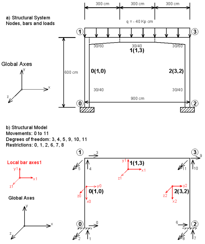
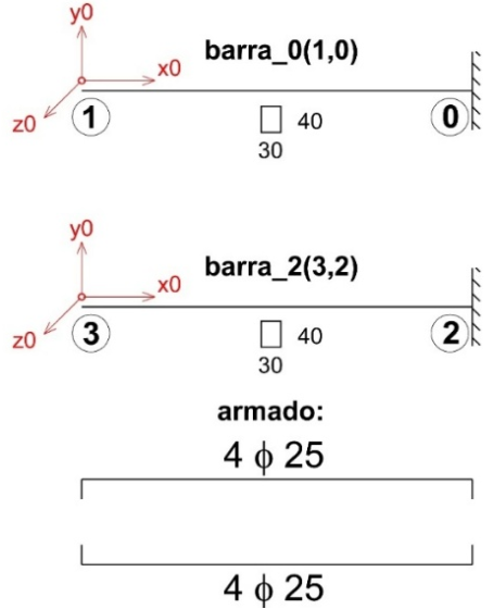
The gantry of this Example is a flat gantry composed of a lintel and two supports of constant section recessed at its base (
Figure 1).
The gantry is designed with H-25 reinforced concrete with AEH-500 and its geometric data and the loads that act are represented in
Figure 1. The units used are Kp and cm and the loads are service loads.
The characteristics of the materials are:
Modulus of Elasticity of Concrete: E = 310000 kp/cm2
Steel modulus of elasticity Es = 2100000 kp/cm2
Concrete Calculation Strength: fcd = 250/1.5 = 166.666 kp/cm2
Steel calculation strength: fyd = 5000/1.15 = 4347,826 kp/cm2
Tensile strength of concrete: fctm = 26 kp/cm2
Reinforcement coating: d' = 3 cm
2.1. Structural System and Structural Model
Figure 1 represents the components of the System and the Structural Model that is going to be analysed.
The calculation is divided into several Phases or Iterations:
1) Calculation in elastic state, without cracking and calculation of the necessary reinforcements (Elastic phase e_).
2) First calculation in cracked state based on the results of the elastic calculation and recalculation of the necessary reinforcements (Cracked phase f_).
3) Second calculation in cracked state based on the results of the First cracked calculation and recalculation of the necessary reinforcements (Cracked phase g_).
4) Third calculation in cracked state based on the results of the Second cracked calculation and recalculation of the necessary reinforcements (Cracked phase h_).
5) Analysis of the results and advisability of performing or not performing a new recalculation, if applicable.
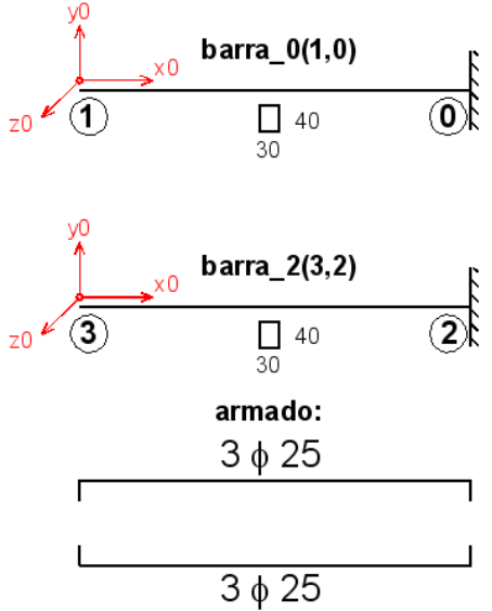
Figure 1. Structural system and structural model.
In
Figure 1 the local axes of the bars (who’s initial and end nodes are shown in parentheses) have been graphed in red, with the subscript of the axis being the number of the bar. It can be seen how in bar 1 the local axes coincide with the global ones.
Next, we proceed with the elastic calculation (Elastic phase, which we will distinguish in its results with e_ at the beginning of the file name).
This Phase was already carried out in Volume I, Chapter 4, to which we refer for a detailed development of the calculation, but now we are going to use a Python program to perform both the elastic calculation and the anelastic calculation in the fissured state, the latter with three iterations whose results we identify with f_, g_ and h_ at the beginning of the name of the generated files. At the end, a module that compares the results is also included.
The outline of the full program is as follows:
Define geometry
Module 1: DEFINING BARS AND KNOTS
Module 2: MATERIALS, PROPERTIES AND SECTIONS
Calculus Uncracked Elastic (e_)
Module 3: C. ELASTIC: FORMAL, TERMS OF LOAD, MR. ELEM., ETC
Module 4: C. ELASTIC: MATRIX CALCULATIONS, RESULTS AND GRAPHS
Module 5: C. ELASTIC: CALCULATING REINFORCEMENT
First Cracked Calculus (f_)
Module 6: FIRST CRACK CALCULATION: FORMALITIES, LOAD TERMS, ETC
Module 7: FIRST CRACKED CALCULATION: RESULTS AND GRAPHS
Module 8: FIRST CRACK CALCULATION: CALCULATING THE REINFORCEMENTS
Second Fissured Calculus (g_)
Module 9: SECOND CRACKED CALCULUS: FORMAL, TERM. LOADING, ETC
Module 10: SECOND CRACKED CALCULUS: RESULTS AND GRAPHS
Module 11: SECOND CRACK CALCULATION: CALCULATING THE REINFORCEMENTS
Third Cracked Stone (h_)
Module 12: THIRD CRACKED CALCULUS: FORMAL, TERM. LOADING, ETC
Module 13: THIRD CRACKED CALCULUS: RESULTS AND GRAPHS
Module 14: THIRD CRACK CALCULUS: CALCULATING THE REINFORCEMENT
Comparison of results
Module 15: COMPARISON RESULTS
2.2. Elastic Calculus
This calculation has been made in Volume I, having obtained the following results.
For the three bars (barra_0, barra_1 and barra_2) these values are obtained:
Displacements and forces at the ends of the bar in local axes of the bar:
e_desp_local_0 = [[0.029031813306961068], [0.005710325854420089], [-0.006447749853223938], [0.0], [0.0], [0.0]]
e_fuerzas_extremos_local_0 = [[-17999.724250315863], [5314.404758532942], [2127335.415426395], [17999.724250315863], [-5314.404758532942], [1061307.4396933706]]
e_desp_local_1 = [[0.005710325854420089], [-0.029031813306961068], [-0.006447749853223938], [-0.005526798489097501], [-0.02903270282207108], [0.006447138095339175]]
e_fuerzas_extremos_local_1 = [[-5314.404758532168], [-17999.724250315932], [-2127335.415426395], [5314.404758532168], [-18000.275749684068], [2127284.8434411664]]
e_desp_local_2 = [[0.02903270282207108], [-0.005526798489097501], [0.006447138095339175], [0.0], [0.0], [0.0]]
e_fuerzas_extremos_local_2 = [[-18000.275749684068], [-5314.404758532649], [-2127284.843441167], [18000.275749684068], [5314.404758532649], [-1061358.011678423]]
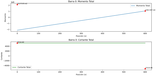
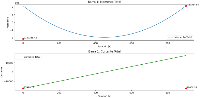
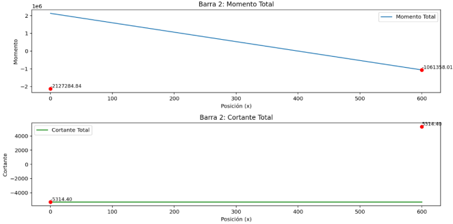
Values of bending moments and shear stresses resulting from the elastic calculation:
The values of moments and shear stresses resulting from the elastic calculation are represented in these graphs:
Figure 2. Bending moments and shear forces for bar_0.
Figure 3. Bending moments and shear forces for bar_1.
Figure 4. Bending moments and shear forces for bar_2.
2.3. Calculation of the Reinforcement of the Elastic Phase (Without Cracking)
Based on the previous elastic calculation, the reinforcements required in each section of each bar are calculated.
The criterion used is as follows:
1) Material:
It is considered an H25 and AE500 standard material, whose useful strengths considering an average action weighting between 1.35 and 1.5 is:
fcu = 166.6 / (1.35 +1.5) * 2 = 116.91 kp/cm2
fyu = 4347.8 / (1.35 +1.5) * 2 = 3051.08 kp/cm2
In the calculation, the useful resistance is considered because the actions introduced are service values and the coefficients of greater actions must be introduced by reducing the strength of the material, except for the flexural-tensile strength which is the characteristic resistance.
2) Type of reinforcement: which can be symmetrical or non-symmetrical:
For bars 0 and 2 (the supports) it is considered symmetrical reinforcement, which is constant throughout the length of the bar.
For bar 1 (beam) it is considered non-symmetrical reinforcement. In this case, the reinforcement varies in each section between two nodes of the polygonal that defines the geometry of the bar.
In both cases it is necessary to add new nodes to those already defined at those points where the momentum function is null (it cuts the x-axis) and where it is maximum (the shear = 0).
In this way, each section of the bar can be put together considering the most unfavorable values among the nodes that limit it, whose moments always have the same sign.
The assembly criterion used is the simplified method of Annex 7 of EHE 08
| [4] | EHE-08. Ministerio de Fomento. Spain. |
[4]
.
Values obtained for reinforcements.
The values of the calculated rebar are stored in the "e_armadura_barra" files of each bar that contain the following information:
Each row corresponds to a section of the bar and consists of 10 columns or values (0 to 9) that include:
1) The x-values that delimit the span of the bar (columns 0, 1)
2) The section of the upper and lower reinforcement required according to the calculation (2, 3). Note: upper and lower according to the local axes of the bar.
3) The section of the upper and lower reinforcements that are arranged when choosing the diameters and their number (4, 5).
4) Number of reinforcements and their diameter in cm (6, 7)
5) Number of reinforcements below and their diameter in cm (8, 9)
Of all these values, the relevant ones are c, d, which correspond to the actual reinforcement that is available for each section of the bar.
In the example we analyzed, the reinforcements are:
Barra_0 and barra_2.
armaduras_barra =
[[0.0, 406.06, 17.4816, 17.4816, 19.6349, 19.6349, 4.0, 2.5, 4.0, 2.5], [406.06, 600.0, 17.4816, 17.4816, 19.6349, 19.6349, 4.0, 2.5, 4.0, 2.5]]
That is: two sections (0, 406.06 and 406.06, 600) with symmetrical reinforcement, with 4 ϕ 25 upper and 4 ϕ 25 lower, whose sections are 19.63 cm2 upper and 19.63 cm2 lower.
Barra_1.
armaduras_barra =
[[0.0, 145.45, 13.6542, 0.4712, 14.0743, 6.2832, 7.0, 1.6, 2.0, 2.0], [145.45, 300.0, 0.0, 16.0857, 4.0212, 18.8496, 2.0, 1.6, 6.0, 2.0], [300.0, 445.45, 1.1660, 22.4410, 4.0212, 25.1328, 2.0, 1.6, 8.0, 2.0], [445.45, 600.0, 1.1660, 22.4410, 4.0212, 25.1328, 2.0, 1.6, 8.0, 2.0], [600.0, 763.63, 0.3062, 16.0859, 4.0212, 18.8496, 2.0, 1.6, 6.0, 2.0], [763.63, 900.0, 13.6539, 0.0, 14.0743, 6.2832, 7.0, 1.6, 2.0, 2.0]]
In these sections, the coordinate x = 445.45 presents a certain deviation from the exact value which is x = 450, where the moment is maximum.
This approximation (1%) is due to the way in which the maximum moment point is calculated, which is where the shear changes its sign (to cut the x-axis), since the shear is the derivative of the bending moment.
For barras_0 and barra_2 is constant:
Figure 5. Reinforcements for bars 0 and 2.
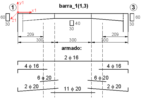
For the barra_1 it is:
Figure 6. Reinforcements for bar 1.
2.4. Starting Values for the Anelastic Calculation (with Cracking)
The starting values required to calculate the reinforced concrete gantry in the cracked state are:
1) The distribution of moments, axial and shear along each bar, obtained from the previous calculation, in this case from the elastic calculation.
2) The reinforcements that has been arranged to resist them.
3) The characteristics of the materials that determine their cracking and cracked stiffness.
That is, it is based on an assumption in an uncracked state that really provides approximate data, since the moments, axial and shear in each bar, when it is cracked, are different from those obtained in the elastic calculation, but it is necessary to start from some value close to the real one and the elastic value is the best option we have.
2.5. First Calculus in the Cracked State
For this first calculation in the cracked state, we will follow the following steps:
Starting from the values obtained from the elastic calculation:
"nodes", which are the nodes that define the polygonal of the bar with its coordinate’s "x" and "y", relative value of the height of the section with respect to the reference section.
Note: It is necessary to distinguish between the "nodes" that define the polygonal of the bar and the "nodes" of the structure that indicate the beginning and end of the bar.
"e_funciones", which define the functions M(x), V(x), M_isost and V_isost resulting from the elastic calculus
"e_armadura_barra", which is the reinforcement of the bar, in sections, and is also the one that results from the previous calculation (elastic).
Detect sign changes in the M(x) function and create "nuevos_nodos" and "signos_tramos":
Next, it is necessary to detect the sign changes in the "moments" function to introduce fictitious nodes in the x-coordinates where the "moments" function changes sign by cutting to the x-axis, and create two new matrices: "nuevos_nodos", which includes all the nodes and sections of the bar polygonal, including the new nodes created, and "signos_tramos" which indicates the signs of the moment (+ or -) for each section of the resulting polygon.
In this example, such matrices are:
Barra_0.
nuevos_nodos =
[[0.0, 1.0]
[406.06, 1.0]
[600. 0, 1.0]]
signos_tramos = ['+', '-']
Barra_1.
nuevos_nodos =
[[0., 1.5]
[145.45, 1.2575]
[300., 1.]
[600., 1.]
[763.63, 1.2727]
[900., 1.5]]
signos_tramos: ['-', '+', '+', '+', '-']
Barra_2.
nuevos_nodos =
[[0.0, 1.0]
[406.06,1.0]
[600. 0, 1.0]]
signos_tramos = ['-', '+']
Calculate the functions of the relative height "y" of the section and the sections of the reinforcements As1 and As2, according to the x-axis.
Next, the functions are calculated: "y" relative height of the section and the sections of the reinforcements "As1" and "As2" taken from the "armaduras_barra" file, which are the sections of the upper and lower reinforcements according to the axes of the bar in all its sections, but in such a way that, if the moment sign in the section is negative, As1 is the upper armor and As2 the lower armor. And analogously, if the momentum is positive, As1 is the lower reinforcement and As2 is the upper one.
Calculate the variable stiffness due to cracking along the bar, in all its sections.
This is the routine that allows you to calculate the stiffness in each x section of the bar taking into account its geometric variation and its variation due to cracking.
To do this, for each value of x (100 values from 0 to light are proposed), a series of values necessary for the cracked calculation are defined as a function of x, which are:
y = relative height of the section in x
Area = area of the section in x
d = useful depth of the section in x
Ib = gross inertia of the section in x
Wb = gross resistant modulus of the section in x
fctm_fl = flexural strength of the section in x
Mf = cracking moment of the section in x
As1 = tensile reinforcement of the section in x
As2 = compression reinforcement of the section in x
ro_1 = amount of the tensile reinforcement of the section in x
ro_2 = amount of the compressed reinforcement of the section in x
X = depth of the neural fiber of the section in x
If = cracked inertia of the section in x
Mx = value of the bending moment acting on the section in x
From these values, the equivalent inertia and the equivalent area of the section in x are calculated, and then their value is divided by those corresponding to the reference section to obtain the function of variation xi_1 (ξ1) of the area and xi_3 (ξ3) of the moment. These are the following values:
Ie = equivalent inertia of the x-section calculated from the above values and divided by I_ref to obtain xi_3.
Ae = equivalent area of the section in x calculated from the above values and divided by A_ref to obtain xi_1. To calculate the equivalent area of the section, an approximate calculation has been made that slightly modifies the gross area.
In this way, a series of functions have been defined for the bar in the "results" matrix where its 100 columns are the functions:
x, y, As1, As2, Mx, Nx, xi_1, xi_3, momento_isostático, v_isostatico
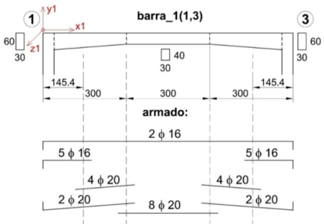
Then the graphs of these functions are created, which for this Ejemplo_1 are as follows:
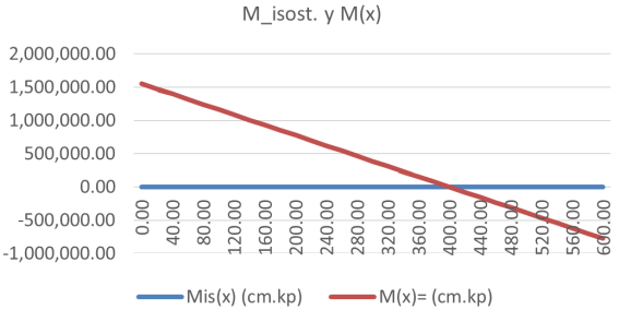
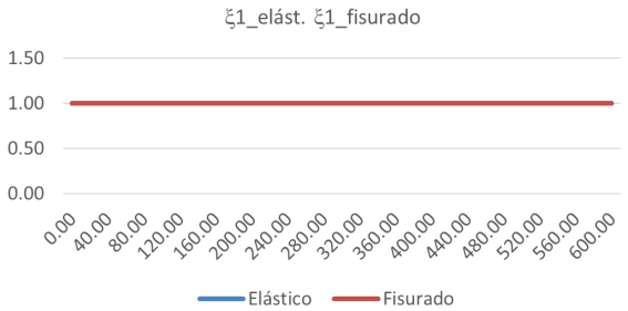
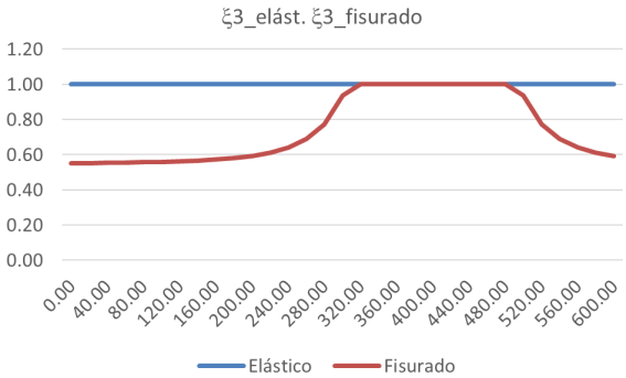
Barra_0
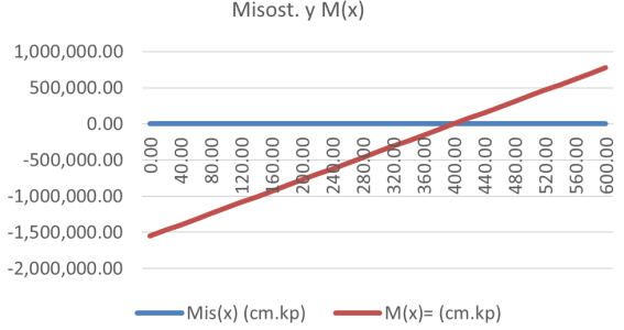
The isostatic moment and isostatic shear are 0 as they have no charges. The moment Mx on its local axes is shown in the graph below and the values of the variation in area and inertia due to geometry and cracking, i.e.: xi_1 = Ae / A_ref and xi_3 = Ie / I_ref are also shown.
Figure 7. Moment M(x) and Isostatic moment of bar 0.
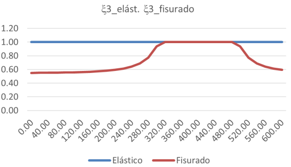
Figure 8. Variation of the section area of bar 0 in elastic and cracked states.
Figure 9. Variation of the inertia of bar 0 in elastic and cracked states.
Barra_1
The graphs are as follows:
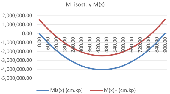
Figure 10. Moment M(x) and Isostatic moment of bar 1.
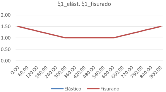
Figure 11. Variation of the section area of bar 1 in elastic and cracked states.
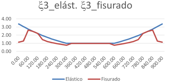
Figure 12. Variation of the inertia of bar 1 in elastic and cracked states.
Barra_2
The graphs are as follows:
Figure 13. Moment M(x) and Isostatic moment of bar 2.
Figure 14. Variation of the section area of bar 2 in elastic and cracked states.
Figure 15. Variation of the inertia of bar 2 in elastic and cracked states.
Calculate the forms, stiffnesses and load terms of the bars in a cracked state.
From the previous functions defined for each bar in a cracked state, the formal functions and load terms are calculated: alpha, lambda_prima, lambda_seg, mu; G_prima and G_seg
These values, for this Example 1 are as follows:
barra_0
alfa = 1.0
lambda_prima = 0,45809386
lambda_seg = 0,40807030
mu = 0,20702736
G_prima = 0.0
G_seg = 0.0
barra_1
alfa = 1,166666667
lambda_prima = 0,32391130
lambda_seg = 0,32391130
mu = 0,19379542
G_prima = -1.569.742,91
G_seg = -1.569.742,91
barra_2
alfa = 1.0
lambda_prima = 0,45809386
lambda_seg = 0,40807030
mu = 0,20702736
G_prima = 0.0
G_seg = 0.0
Calculation of the coefficients to form the elemental stiffness matrix of each bar according to its connection.
For each bar, the coefficients of its elemental stiffness matrix are calculated that allow such a matrix to be constructed on local axes.
Previously, it is necessary to calculate the stiffness of ro_prima, ro_seg and eta bars.
From these values, in the calculation program, the coefficients of the stiffness matrix are calculated for the following cases (In this case all the bars are recessed-recessed):
recessed–recessed (A, B, C1, C2, C3, D1 and D2)
recessed–articulated (Ad, Bd, C1d and D1d)
articulated-recessed (Ai, Bi, C2i and D2i)
articulated-articulated (A_art)
Calculation of the elementary stiffness matrix and the equivalent node actions of each bar, according to its connection.
With these values, the elemental stiffness matrix and the equivalent knot actions of the bar are calculated, taking into account its connection to the nodes at its ends (recessed or articulated). These are the "f_MR_elem" and "f_AE_elem" arrays that are saved in each bar folder.
The equivalent action values are calculated to define the equivalent action vector of the bar in the cracked state
In this example they are:
barra_0 and barra_2:
“f_MR_elem” = [[620000.00, 0.0, 0.0, -620000.00, 0.0, 0.0], [0.0, 2040.45, 588216.39, 0.0, -2040.45, 636053.81], [0.0, 588216.39, 234141978.81, 0.0, -588216.39, 118787857.94], [-620000.00, 0.0, 0.0, 620000.0, 0.0, 0.0], [0.0, -2040.45, 588216.39, 0.0, 2040.45, -636053.81], [0.0, 636053.81, 118787857.9, 0.0, -636053.81, 262844428.19]]
“f_AC_equiv” = [[0.] [0.] [-0.] [0.] [0.] [-0.]]
barra_1:
“f_MR_elem” = [[482222.22, 0.0, 0.0, -482222.22, 0.0, 0.0], [0.0, 1045.81, 470615.64, 0.0, -1045.81, 470615.64], [0.0, 470615.64, 265003226.71, 0.0, -470615.64, 158550849.71], [-482222.22, 0.0, 0.0, 482222.22, 0.0, 0.0], [0.0, -1045.81, -470615.64, 0.0, 1045.81, -470615.64], [0.0, 470615.64, 158550849.71, 0.0, -470615.64, 265003226.71]]
f_AC_equiv = [[0] [-18000.00] [-3.032.108,42] [0] [-18000.00] [3.032.108,42]]
Transform the elementary stiffness matrices and the vectors of actions equivalent to global coordinates and save them in each bar folder.
The next step is to pass each array "f_MR_elem" and the vector "f_AC_equiv" to global coordinates using the "T" axis transformation matrix, which yields the matrix "f_MR_elem_c_glob" and the vector "f_AC_equiv_elem_c_global".
Assemble the global stiffness matrix and the global force vector of the structure and apply the boundary conditions to the global stiffness matrix and the global force vector of the structure.
From the above "f_MR_elem_c_glob" and the vector "f_AC_equiv_elem_c_global", which are in global coordinates, the next step is to assemble the global stiffness matrix "f_K_global_total" and the global equivalent action vector "f_F_global_total".
Next, the boundary conditions are applied, which are restricted movements and whose value is 0.
To cancel the equations corresponding to these movements, we proceed to cancel all the matrix coefficients of the row and column of the global matrix and place a 1 in the diagonal element.
With the equivalent actions vector, the shares corresponding to these restricted movements are also cancelled.
Solve the equation and obtain the global displacement vector.
Solving the matrix equation yields the vector of displacements in global coordinates "f_desplazamientos". In our example it is as follows:
f_desplazamientos = [[0.0], [0.0], [0.0], [0,00542383], [-0,02903226], [-0,00891177], [0.0], [0.0], [0.0], [0.0], [0.0], [-0,00542383], [-0,02903226], [0,00891177]]
Extract the end displacements of each bar into global coordinates and transform them into local coordinates of the bar.
From the global displacement vector, those corresponding to each bar are extracted, in global coordinates, and it is transformed to the local coordinates of the bar by means of the transformation matrix "T" resulting in "f_desp_local.
By means of the elementary stiffness matrix of each bar, its vector of end movements and its vector of equivalent end actions, all of them on local axes, the resulting actions at the ends of the bar are calculated.
Using the elementary stiffness matrix of the bar "f_MR_elem", its vector of extreme movements "f_desp_local" and its vector of equivalent actions of the extreme "f_AE_equiv", the "f_fuerzas_extremos_local" of each bar are calculated.
For this example, they are:
barra_0:
f_fuerzas_extremos_local = [[-18000.00], [5230.98], [1635606.72], [18000.00], [-5230.98], [817803.36]]
barra_1:
f_fuerzas_extremos_local = [[[-5230.98], [-18000.00], [-1635606.72], [5230.98], [-18000.00], [1635606.72]]
barra_2:
f_fuerzas_extremos_local = [[-18000.00], [-5230.98], [-1635606.72], [18000.00], [5230.98], [-817803.36]]
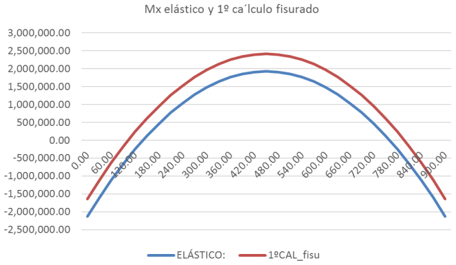
Graph of moments in elastic and cracked state.
The graphs of moments in elastic and cracked states for bar 1 are as follows:
The results are these:
Figure 16. Graph of moments in elastic and cracked state for bar 1.
If the graphs in bar 1 are compared with those of the elastic calculation, it can be seen that the extreme moment has gone from -21.27 mt in the elastic calculus to -16.35 mt in the fissured calculation.
Calculate the reinforcement in a cracked state.
The reinforcements for the cracked state are calculated and the following values are obtained for this example:
barra_0 and barra_2:
For barras_0 and barra_2 the reinforcement is constant:
As1 = As2 = 12.71 cm2
3ϕ25 (14.73 cm2) are proposed
Figure 17. Reinforcement scheme resulting from the first cracked calculation for bars 0 and 2.
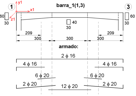
barra_1:
For the barra_1 it is:
Interval x 0-209 and interval x 691-900:
As_sup = 10.15 cm2, 6ϕ16 (12.06 cm2) is proposed
As_inf = 0.00 cm2, 2ϕ20 (6.28 cm2) is proposed
Interval x 209-300 and interval x 600-691:
As_sup = 0.00 cm2, 2ϕ16 (4.02 cm2) is proposed
As_inf = 23.30 cm2, 8ϕ20 (25.13 cm2) is proposed
Interval x 300-600:
As_sup = 0.00 cm2, 2ϕ16 (4.02 cm2) is proposed
As_inf = 34.56 cm2, 11ϕ20 (34.56 cm2) is proposed
Figure 18. Reinforcement scheme resulting from the first cracked calculation for bar 1.
2.6. Second Calculation in Cracked State and Subsequent
The second calculation in the cracked state and the subsequent ones are performed in the same way as the first.
Three more calculations have been carried out in a cracked state, always starting from the results of the previous calculation (cracked 2, cracked 3 and cracked 4)
2.7. Results Obtained and Comparison of Results
The results obtained for the elastic calculation and the 4 calculations in cracked state are the following:
Table 1. Elastic calculation results.
RESULTADOS: CÁLCULO ELÁSTICO | |
| Barra_0 | Barra_1 | Barra_2 |
N'= | -18.000,00 | -5.314,29 | -18.000,00 |
V'= | 5.314,29 | -18.000,00 | -5.314,29 |
M´= | 2.127.233,57 | -2.127.233,57 | -2.127.233,57 |
N"= | 18.000,00 | 5.314,29 | 18.000,00 |
V"= | -5.314,29 | -18.000,00 | 5.314,29 |
M´´= | 1.063.616,79 | 2.127.233,57 | -1.063.616,79 |
Table 2. Results of the first calculation in cracked state.
RESULTADOS: 1º CÁLCULO FISURADO |
| Barra_0 | Barra_1 | Barra_2 |
N'= | -18.000,00 | -5.230,98 | -18.000,00 |
V'= | 5.230,98 | -18.000,00 | -5.230,98 |
M´= | 1.635.606,72 | -1.635.606,72 | -1.635.606,72 |
N"= | 18.000,00 | 5.230,98 | 18.000,00 |
V"= | -5.230,98 | -18.000,00 | 5.230,98 |
M´´= | 817.803,36 | 1.635.606,72 | -817.803,36 |
Table 3. Results of the second calculation in cracked state.
RESULTADOS: 2º CÁLCULO FISURADO |
| Barra_0 | Barra_1 | Barra_2 |
N'= | -18.000,00 | -4.593,84 | -18.000,00 |
V'= | 4.593,84 | -18.000,00 | -4.593,84 |
M´= | 1.547.824,06 | -1.547.824,06 | -1.547.824,06 |
N"= | 18.000,00 | 4.593,84 | 18.000,00 |
V"= | -4.593,84 | -18.000,00 | 4.593,84 |
M´´= | 773.912,03 | 1.547.824,06 | -773.912,03 |
Table 4. Results of the third calculation in cracked state.
RESULTADOS: 3º CÁLCULO FISURADO |
| Barra_0 | Barra_1 | Barra_2 |
N'= | -18.000,00 | -4.627,44 | -18.000,00 |
V'= | 4.627,44 | -18.000,00 | -4.627,44 |
M´= | 1.551.755,34 | -1.551.755,34 | -1.551.755,34 |
N"= | 18.000,00 | 4.627,44 | 18.000,00 |
V"= | -4.627,44 | -18.000,00 | 4.627,44 |
M´´= | 775.877,67 | 1.551.755,34 | -775.877,67 |
Table 5. Results of the fourth calculation in cracked state.
RESULTADOS: 4º CÁLCULO FISURADO |
| Barra_0 | Barra_1 | Barra_2 |
N'= | -18.000,00 | -4.545,50 | -18.000,00 |
V'= | 4.545,50 | -18.000,00 | -4.545,50 |
M´= | 1.577.253,46 | -1.577.253,46 | -1.577.253,46 |
N"= | 18.000,00 | 4.545,50 | 18.000,00 |
V"= | -4.545,50 | -18.000,00 | 4.545,50 |
M´´= | 788.626,73 | 1.577.253,46 | -788.626,73 |
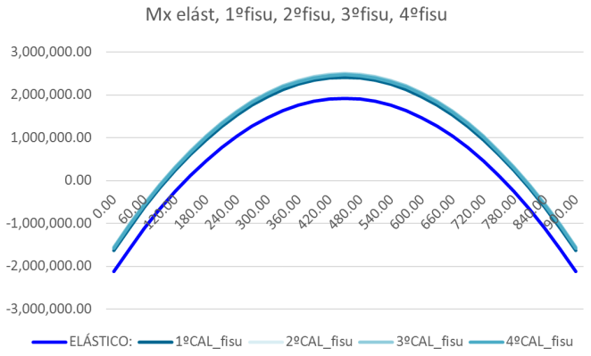
To compare the results, we analyze the bending moment graphs of bar 1.
Figure 19. Bending moment graph for elastic calculations and 1st, 2nd, 3rd and 4th calculations in cracked state for bar 1.
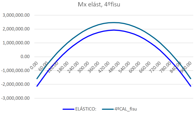
Figure 20. Bending moment graph for elastic calculations and 4th calculation in cracked state for bar 1.
If we compare the results of the last 3 calculations, we can see that they practically coincide.
The resulting reinforcement of the fourth cracked calculation is as follows:
Figure 21. Drawing of reinforcement resulting from the fourth cracked calculation for bars 0 and 2.
Figure 22. Drawing of reinforcement resulting from the fourth cracked calculation for bar 1.