The design and analysis of helical gears with involutes profiles is the primary focus of this study. The most widely utilized gearing system in use today is the involutes gear profile. Power and torque are typically transmitted through them. When compared to other forms of transmission, the efficiency of power transmission via gears is extremely high. Bending and contact stress are the main causes of gear tooth failure. The current study examines helical gear, which has to do with slag transfer in the steel production sector. The most affected stress concentrated location of any set of gears in the slag port transfer car (SPTC) gear box is identified by examining the contact stresses for the current design set of gears. The high stress concentration gear set was redesigned with a constant (45mm) face width at various Helix angles (14, 15, 16, 17, 19^, 20 ̊, 25^, and 30 ̊) and a constant pressure angle (20). To calculate the contact stresses between two gears that are mating. The robust and cutting-edge solid modeling program AUTODESK FUSION 360 creates a three-dimensional solid model. The ANSYS Workbench module was utilized to do the numerical analysis. The outcomes of the workbench module for ANSYS. The current study is helpful in quantifying the previously mentioned factors, which aids in the safe and effective design of the helical gear in the SPTC Gearbox.
| Published in | International Journal of Mechanical Engineering and Applications (Volume 12, Issue 3) |
| DOI | 10.11648/j.ijmea.20241203.12 |
| Page(s) | 71-80 |
| Creative Commons |
This is an Open Access article, distributed under the terms of the Creative Commons Attribution 4.0 International License (http://creativecommons.org/licenses/by/4.0/), which permits unrestricted use, distribution and reproduction in any medium or format, provided the original work is properly cited. |
| Copyright |
Copyright © The Author(s), 2024. Published by Science Publishing Group |
Power, Torque, Helical Angle, Pressure Angle, Gear, Fusion 360, ANSYS
System Description | |
|---|---|
Specifications for Hardware | Processor type: Intel |
Core i5 RAM: 8 GB of 64-bit RAM | |
1 TB of storage | |
Display | 20-inch color LCD |
Specifications for software | Fusion 360 Autodesk |
Workbench ANSYS 2021 R2 | |
Fusion 360 Autodesk | |
S.No | Description | Stage 1 | Stage 2 | Stage 3 | |||
|---|---|---|---|---|---|---|---|
PINIO N | GEAR | PINIO N | GEAR | PINIO N | GEA R | ||
1 | Normal Module | 3 | 4 | 7 | |||
2 | Numberof Teeth | 16 | 64 | 16 | 71 | 15 | 54 |
3 | Helix Angle | 16.26 | 14.835 | 14.983 | |||
4 | Pressure Angle | 20 | 20 | 20 | |||
5 | Reference Diameter | 50 | 200 | 66.21 | 293.79 | 108.70 | 391.30 |
6 | Tip CircleDiameter | 56 | 206 | 77.41 | 298.59 | 127.60 | 400.40 |
7 | Root Circle Diameter | 42.50 | 192.50 | 59.41 | 280.59 | 96.10 | 368.90 |
8 | Clearance | 0.75 | 1 | 0.35 | |||
9 | Centre Distance | 125 | 180 | 250 | |||
ChemicalComposition | Properties | Mechanical Properties of Structural Steel | |||
|---|---|---|---|---|---|
Carbon | 0.22 | Density | 7850 g/m3 | Tensile Strength (MPa) | 320 |
Silicon | 0.280 | Specific heat capacity | 486 J/(kg*K) | Young’s modulus (MPa) | 210 |
Manganese | 1.03 | Electric resistivity | 1.62*10-7 ohm*m | Elongation | 38 |
Phosphorus | 0.040 | Electrical Resistivity | 0.72 x 10⁻⁶Ω.m | Poisson’s ratio | 0.3 |
Sulphur | 0.050 | Yield strength (MPa) | 250 | ||
S.No | Analysis | Total deformation | Equivalent Stress | Safety Factor | |||
|---|---|---|---|---|---|---|---|
Min | Max | Min | Max | Min | Max | ||
1 | Load on static structural 3 helical gear | 0 | 0.086706 | 0.03179 | 605.46 | 0.14237 | 15 |
2 | Impact on static structural 4 helical gear | 0 | 0.07504 | 0.086404 | 355.61 | 0.2424 | 15 |
3 | Impact on static structural 7 helical gear | 0 | 0.026257 | 0.0010538 | 86.709 | 0.99413 | 15 |
4 | Impact on static structural 7 helical gear 14 angle | 0 | 0.016367 | 0.0033613 | 69.736 | 1.2361 | 15 |
5 | Impact on static structural 7 helical gear 15 angel | 0 | 0.017936 | 0.0019035 | 47.64 | 1.8094 | 15 |
| [1] | "Stress Analysis of Gearbox," Pravin M., BR Kharde, and BR Borkar, IRACST, Volume: 2, Issue: 3, June 2012. |
| [2] | "A review paper on design and analysis of helical gear using ANSYS, FEM & AGMA standards" by PrashantModi was published in the January 2017 issue of IRJET. |
| [3] | Mechanica Confab, Volume: 2, No. 1, Jan. 2013, Pratik Gulaxea, N. P. Awate, "Design, Modeling& Analysis of Gear Box for Material Handling Trolley: A Review." |
| [4] | "Contact Stress Analysis of Helical Gear by Using AGMA and ANSYS," S. SaiAnushaSatish Reddy, P. Chaska, and M. Manoj, IJSEAT, Volume: 2, Issue 12, Dec. 2014. |
| [5] | A case study on various defects found in a gear system is presented by V. S. Panwar and S. P. Mogal in IRJET, Volume 02, Issue 03, and June 2015. |
| [6] | A Jammal, Ch. "An Experimental Study On High Speed Helical Gears Misalignments and Dynamic Behavior under Random Loading" (GU, H Wang, R Li, Y Song, and YK Rong), ICMAE, 7th International Conference, 2016. |
| [7] | "Stress Analysis of Helical Gear by Finite Element Method," Govind T. Sarkar, YL Yenarkar, and DV Bhope, IJMERR, Volume: 2, No. 4, October 2013. |
| [8] | Process parameters optimization for helical gears precision forging with damage minimization: W Feng and L Hua, International Conference on Manufacturing and Distribution (ICDMA) -2010. |
| [9] | "Modal Analysis of the Helical Gear of the Increasing Gear Box for Wind Generator," Z Yucheng and Wu Baolin, ICIMA, International Conference-2010. |
| [10] | R. L. Norton, Machine Design: An Integrated Approach, Pearson Hall Inc., New Jersey, 1996. |
| [11] | Yonatan, F., Spur Gear Teeth Variable Mesh Stiffness Using FEM, M. sc. thesis, Addis Ababa University's Department of Mechanical Engineering. |
| [12] | Machine Design: An Integrated Approach by R. L. Norton, Prentice-Hall Inc., New Jersey, 1996. |
| [13] | A Static Analysis of Composite Helical Gears Using Three-dimensional Finite Element Method, Vijayarangan, S. and Ganesan, N., Computers & Structures, 49, pp. 253-268, 1993. |
| [14] | Maitra, G. M. (2014) Tata McGraw-Hill, New Delhi; Hand Book of Gear Design. |
| [15] | Marappan, S. &Verkataramana, 2014, CAD Center, India, ANSYS Reference Guide. |
| [16] | Finite Element Analysis of Stresses in Involutes Spur Helical Gear by Shreyash D. Patel, M. Sc. University of Texas at Arlington, 2019; thesis. |
APA Style
Kanagaraj, A., Pandurangan, S. M., Durai, S., Gopi, A. (2024). The Design and Analysis of the Helical Gear in the Car Gear Box for the Slag Port Transfer. International Journal of Mechanical Engineering and Applications, 12(3), 71-80. https://doi.org/10.11648/j.ijmea.20241203.12
ACS Style
Kanagaraj, A.; Pandurangan, S. M.; Durai, S.; Gopi, A. The Design and Analysis of the Helical Gear in the Car Gear Box for the Slag Port Transfer. Int. J. Mech. Eng. Appl. 2024, 12(3), 71-80. doi: 10.11648/j.ijmea.20241203.12
AMA Style
Kanagaraj A, Pandurangan SM, Durai S, Gopi A. The Design and Analysis of the Helical Gear in the Car Gear Box for the Slag Port Transfer. Int J Mech Eng Appl. 2024;12(3):71-80. doi: 10.11648/j.ijmea.20241203.12
@article{10.11648/j.ijmea.20241203.12,
  author = {Anandan Kanagaraj and Senthilkumar Marakkanappatti Pandurangan and Saravavan Durai and Arunkumar Gopi},
  title = {The Design and Analysis of the Helical Gear in the Car Gear Box for the Slag Port Transfer
},
  journal = {International Journal of Mechanical Engineering and Applications},
  volume = {12},
  number = {3},
  pages = {71-80},
  doi = {10.11648/j.ijmea.20241203.12},
  url = {https://doi.org/10.11648/j.ijmea.20241203.12},
  eprint = {https://article.sciencepublishinggroup.com/pdf/10.11648.j.ijmea.20241203.12},
  abstract = {The design and analysis of helical gears with involutes profiles is the primary focus of this study. The most widely utilized gearing system in use today is the involutes gear profile. Power and torque are typically transmitted through them. When compared to other forms of transmission, the efficiency of power transmission via gears is extremely high. Bending and contact stress are the main causes of gear tooth failure. The current study examines helical gear, which has to do with slag transfer in the steel production sector. The most affected stress concentrated location of any set of gears in the slag port transfer car (SPTC) gear box is identified by examining the contact stresses for the current design set of gears. The high stress concentration gear set was redesigned with a constant (45mm) face width at various Helix angles (14, 15, 16, 17, 19^, 20 ̊, 25^, and 30 ̊) and a constant pressure angle (20). To calculate the contact stresses between two gears that are mating. The robust and cutting-edge solid modeling program AUTODESK FUSION 360 creates a three-dimensional solid model. The ANSYS Workbench module was utilized to do the numerical analysis. The outcomes of the workbench module for ANSYS. The current study is helpful in quantifying the previously mentioned factors, which aids in the safe and effective design of the helical gear in the SPTC Gearbox.
},
 year = {2024}
}
TY  - JOUR
T1  - The Design and Analysis of the Helical Gear in the Car Gear Box for the Slag Port Transfer

AU  - Anandan Kanagaraj
AU  - Senthilkumar Marakkanappatti Pandurangan
AU  - Saravavan Durai
AU  - Arunkumar Gopi
Y1  - 2024/08/20
PY  - 2024
N1  - https://doi.org/10.11648/j.ijmea.20241203.12
DO  - 10.11648/j.ijmea.20241203.12
T2  - International Journal of Mechanical Engineering and Applications
JF  - International Journal of Mechanical Engineering and Applications
JO  - International Journal of Mechanical Engineering and Applications
SP  - 71
EP  - 80
PB  - Science Publishing Group
SN  - 2330-0248
UR  - https://doi.org/10.11648/j.ijmea.20241203.12
AB  - The design and analysis of helical gears with involutes profiles is the primary focus of this study. The most widely utilized gearing system in use today is the involutes gear profile. Power and torque are typically transmitted through them. When compared to other forms of transmission, the efficiency of power transmission via gears is extremely high. Bending and contact stress are the main causes of gear tooth failure. The current study examines helical gear, which has to do with slag transfer in the steel production sector. The most affected stress concentrated location of any set of gears in the slag port transfer car (SPTC) gear box is identified by examining the contact stresses for the current design set of gears. The high stress concentration gear set was redesigned with a constant (45mm) face width at various Helix angles (14, 15, 16, 17, 19^, 20 ̊, 25^, and 30 ̊) and a constant pressure angle (20). To calculate the contact stresses between two gears that are mating. The robust and cutting-edge solid modeling program AUTODESK FUSION 360 creates a three-dimensional solid model. The ANSYS Workbench module was utilized to do the numerical analysis. The outcomes of the workbench module for ANSYS. The current study is helpful in quantifying the previously mentioned factors, which aids in the safe and effective design of the helical gear in the SPTC Gearbox.

VL  - 12
IS  - 3
ER  -
Department of Mechanical Engineering, P. S. V College of Engineering and Technology, Krishnagiri, India
Department of Mechanical Engineering, P. S. V College of Engineering and Technology, Krishnagiri, India
Department of Mechanical Engineering, P. S. V College of Engineering and Technology, Krishnagiri, India
Department of Mechanical Engineering, P. S. V College of Engineering and Technology, Krishnagiri, India
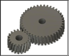
Figure 1. 3DModel for Meshing Gear Set.
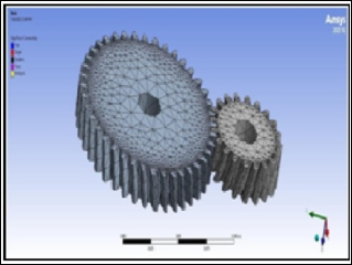
Figure 2. Simulation Diagram for Proposed System.
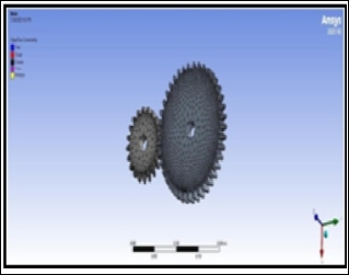
Figure 3. 3D Model for Module 4 Helical Gear.
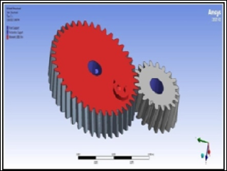
Figure 4. Meshing Gear Set 3D Model.
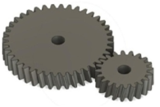
Figure 5. Proposed System's Simulation Diagram.
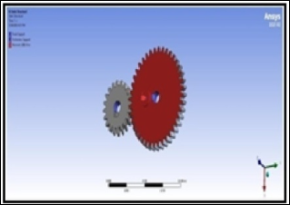
Figure 6. Module 7 Helical Gear 3D Model.
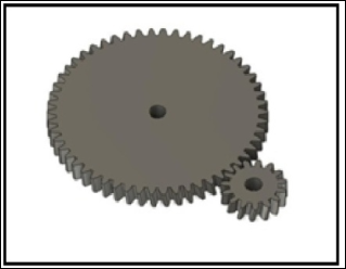
Figure 7. Meshing Gear 3D Model Assign.
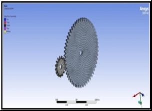
Figure 8. Meshing Gear 3D Model Assign.
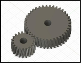
Figure 9. Helical Gear Set Design.
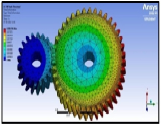
Figure 10. Totaldeformation.
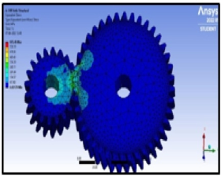
Figure 11. Equivalent stress.
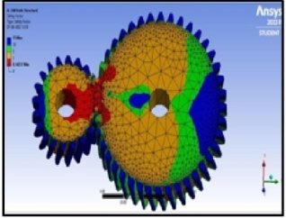
Figure 12. Factor of safety.
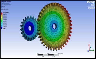
Figure 13. Total deformation.
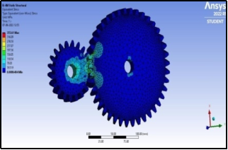
Figure 14. Equivalent stress.
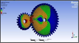
Figure 15. Factor of safety.
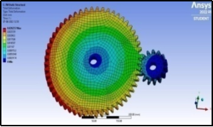
Figure 16. Total deformation.
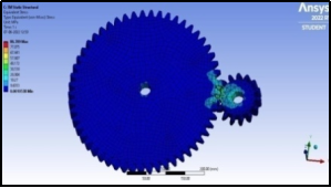
Figure 17. Equivalent stress.
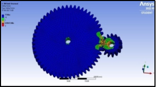
Figure 18. Factor of safety.
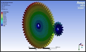
Figure 19. Total deformation.
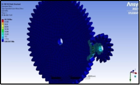
Figure 20. Equivalent stress.
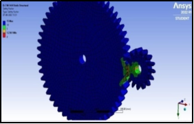
Figure 21. Factor of safety.
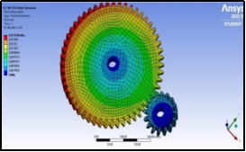
Figure 22. Total deformation.
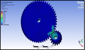
Figure 23. Equivalent stress.
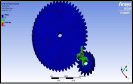
Figure 24. Factor of safety.
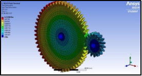
Figure 25. Totaldeformation.
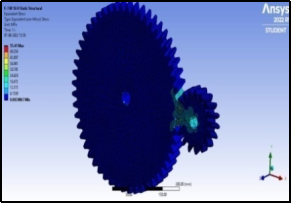
Figure 26. Equivalentstress.
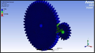
Figure 27. Factorofsafety.
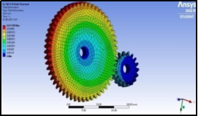
Figure 28. Totaldeformation.
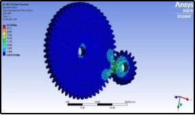
Figure 29. Equivalentstress.

Figure 30. Factorofsafety.
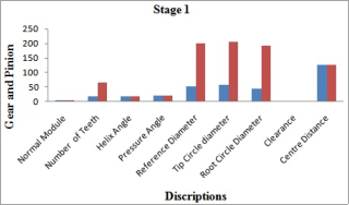
Figure 31. Stage I.
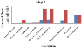
Figure 32. Stage II.
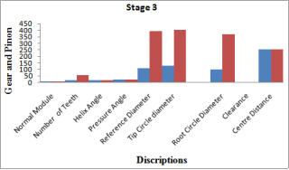
Figure 33. Stage III.
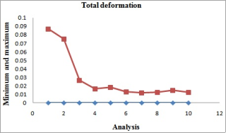
Figure 34. Factor of safety.
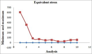
Figure 35. Factor of safety.
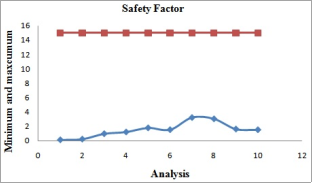
Figure 36. Factor of safety.
Information

