Research Article | | Peer-Reviewed

Design and Experimental Implementation of a CNC Milling Process for a Pneumatic Cylinder Base

Received: 12 July 2026     Accepted: 23 July 2026     Published: 17 August 2026
Views:       Downloads:
Abstract

Pneumatic-cylinder bases contain planar interfaces, stepped regions, hole patterns, and threaded features whose relative accuracy directly affects assembly and sealing performance. This study develops and experimentally implements a milling-oriented process-planning framework for a representative cylinder-base component. The workflow links functional requirements to datum selection, operation sequencing, cutting-tool selection, computer-aided manufacturing (CAM) programming, toolpath verification, and shop-floor execution. The component was modeled and programmed in Mastercam 2022. The adopted sequence comprised face milling, contour and pocket milling, center drilling, drilling, tapping, chamfering, and final inspection. A D60 face mill, end mills, 4.2 and 6.8 mm drills, spot drill, chamfer tool, and M5/M8 taps were used. The NC programs were verified through graphical simulation before machining on a Manford CNC machining center. An aluminum blank available in the workshop was used to demonstrate the process, although the original design was intended for gray cast iron. The completed component reproduced the required overall geometry and hole arrangement and was suitable for assembly trials. Visual inspection, however, revealed cutter marks and a surface condition inferior to the original specification; therefore, sealing performance and long-term load capacity were not claimed. The results show that a design-to-CAM process chain can reduce programming ambiguity and provide a reproducible route for low-volume production, while also demonstrating that material substitution and the absence of quantitative surface-metrology data must be explicitly considered when assessing manufacturing conformity. Accordingly, the experimental evidence should be interpreted as verification of workflow implementation and qualitative geometric feasibility, not as quantitative qualification of dimensional accuracy, surface integrity, or pneumatic function.

Published in Industrial Engineering (Volume 10, Issue 2)
DOI 10.11648/j.ie.20261002.11
Page(s) 36-48
Creative Commons

This is an Open Access article, distributed under the terms of the Creative Commons Attribution 4.0 International License (http://creativecommons.org/licenses/by/4.0/), which permits unrestricted use, distribution and reproduction in any medium or format, provided the original work is properly cited.

Copyright

Copyright © The Author(s), 2026. Published by Science Publishing Group

Keywords

Pneumatic Cylinder Base, CNC Milling, Process Planning, Mastercam, Toolpath Verification, Machining Accuracy

1. Introduction
CNC milling is a principal manufacturing route for components that combine planar surfaces, cavities, shoulders, and accurately positioned holes. Current research increasingly treats milling performance as a coupled problem involving cutting mechanics, machine dynamics, toolpath generation, and process planning rather than as a sequence of isolated operations . Recent prototype-development and machining studies have also emphasized the need to connect CAD/CAM-based planning with experimentally verified manufacturing outcomes, particularly in small-batch and laboratory production .
Process planning for prismatic mechanical components requires reliable datum selection, setup definition, operation sequencing, and workholding. Inaccurate locating or clamping can cause cumulative positioning errors, poor accessibility, and unstable cutting. Recent reviews and fixture-design studies therefore emphasize the integrated treatment of setup planning, fixture configuration, and machining requirements . A pneumatic-cylinder base is an appropriate case study because it combines planar mounting interfaces, hole patterns, threaded features, and a raised lug whose relative positions must be preserved during machining.
Machining allowance and operation-level decisions strongly influence cutting force, energy consumption, machining time, and final dimensional accuracy. Recent studies have treated allowance distribution and cutting-condition selection as multi-objective problems rather than relying exclusively on empirical workshop rules . These findings support the use of a structured roughing-finishing sequence and explicit verification of the material remaining before finish machining.
Cutting parameters must be selected within the practical capability of the machine-tool-workpiece system. Feed per tooth, spindle speed, axial depth, and radial engagement influence chip thickness, cutting force, vibration, and surface generation. Experimental optimization and predictive modelling can balance productivity and surface quality, but the resulting optimum remains specific to the machine, cutter, workpiece material, and setup . Consequently, CAM recommendations should be treated as initial process values and verified through simulation and controlled machining trials.
Workholding is another determinant of machining accuracy. Conventional vises are effective for compact prismatic blanks, whereas fractal, flexible, pneumatic, and multi-part fixtures can improve conformity, accessibility, and productivity for non-standard geometries . Smart-fixture research further shows that fixture compliance and workpiece slenderness must be considered when machining flexible components .
The finite element method and mechanistic force models are widely used to predict cutting force, deflection, chatter, and machining error. Recent thin-wall studies have reported experimentally validated force-deflection behaviour, efficient position-dependent dynamic models, and improved prediction through cutter-workpiece engagement modelling . Although the present cylinder base is considerably more rigid than a thin-walled part, these studies establish the broader need for stable support and gradual cutter engagement.
Toolpath direction and engagement strategy influence both load continuity and surface integrity. Comparative studies of up- and down-milling, supported thin-wall machining, chatter monitoring, and micro-milling mechanics show that controlled engagement and adequate structural support reduce deformation and process instability . These results also reinforce the importance of verifying tool access, linking motion, and local engagement before NC-code transfer.
Digital manufacturing platforms integrate geometric modelling, stock definition, tool selection, toolpath generation, collision checking, and NC-code post-processing. Their effectiveness nevertheless depends on correct work-coordinate selection, safe approach and retract levels, and validation on the target machine. Mastercam documentation and prototype CNC-machine studies similarly demonstrate that digital completeness does not remove the need for physical calibration and experimental verification .
Existing studies provide extensive knowledge on milling mechanics, optimization, and fixturing, but comparatively few studies document a complete and reproducible process chain for a pneumatic-cylinder base using original CAM settings and workshop data. This study therefore develops a structured route from component analysis to Mastercam programming, NC verification, CNC machining, and post-process assessment. The contribution is application-oriented: it makes explicit the relationship between datum selection, operation sequence, tool choice, CAM verification, and the observed manufacturing result. The study also discusses the implications of machining an aluminum trial blank instead of the ferrous material considered during the initial design stage . Accordingly, the principal contribution is the documented implementation and transferability of the integrated CAD/CAM/CNC workflow; comprehensive manufacturing and functional qualification is outside the present scope.
2. Materials and Methods
2.1. Datum Establishment and Feature-Based Operation Planning
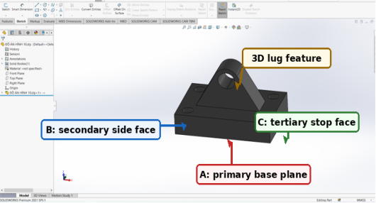
This subsection was retained because datum establishment provides the direct link between the component geometry and the CAM program. For both pneumatic-cylinder-base variants, the broadest available stock surface was selected as the initial rough locating surface. The first face-milling operation generated a stable planar datum (datum A), which was subsequently maintained as the principal support surface. Two adjacent mutually perpendicular faces were then used as secondary and tertiary references (datums B and C). This 3-2-1 locating scheme constrained the workpiece in a conventional machine vise while avoiding redundant constraints and limiting datum-transfer error between planar milling and hole-making operations.
The machining sequence was organized according to feature dependency rather than according to the order in which CAM commands were created. Datum generation was performed first using the 60 mm face mill. Bulk material was then removed from the external contour, pocketed regions, and the three-dimensional lug geometry by rough milling, after which finish passes were applied to the functional planes and free-form surfaces. Hole manufacture followed the milled datums: spot drilling established the hole centers, 4.2 and 6.8 mm drills produced the tapping diameters, and M5 and M8 taps generated the threaded features. Chamfering, edge deburring, and final visual and dimensional inspection completed the process. Locating the hole operations after the principal surfaces had been established preserved the positional relationship between the hole pattern and the mounting faces.
The same planning logic was used for the two component variants, but the toolpath content differed according to geometry. The predominantly prismatic base was processed mainly through face, contour, drilling, and tapping cycles, whereas the lug-type component additionally required three-dimensional roughing and flowline finishing of the inclined surface. Thus, the datum structure remained common, while the feature-specific operations were adapted to each model. This approach reduced unnecessary changes of the work coordinate system and provided a consistent reference for the simulation, NC-code generation, and subsequent comparison between the CAM model and the manufactured products. The planning logic and datum scheme are summarized in Figure 1.
Figure 1. Three-dimensional CAD model of the lug-type pneumatic-cylinder base with the datum system used for process planning.
As illustrated in Figure 1, the broad bottom surface was selected as primary datum A because it provides the largest and most stable supporting area during setup. The long side face was assigned as secondary datum B to constrain lateral motion, whereas the orthogonal end face was used as tertiary datum C to remove the remaining in-plane degree of freedom. This A-B-C datum system establishes a consistent reference for face milling, side milling, hole positioning, and the subsequent three-dimensional machining of the lug feature.
2.2. Cam Programming and Toolpath Verification
The CAM stage was treated as the central process-planning activity rather than merely as a code-generation step. The original three-dimensional models were imported into Mastercam 2022, the stock dimensions and work coordinate system were defined, and each machining feature was assigned an operation consistent with the datum sequence established in Section 2.1. The program was divided into face milling, three-dimensional roughing and finishing, drilling, and tapping. This decomposition made the sequence traceable and allowed each operation to be verified independently before post-processing.
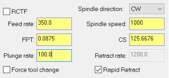
Figure 2. Original Mastercam cutting-data entry for the face-milling operation.
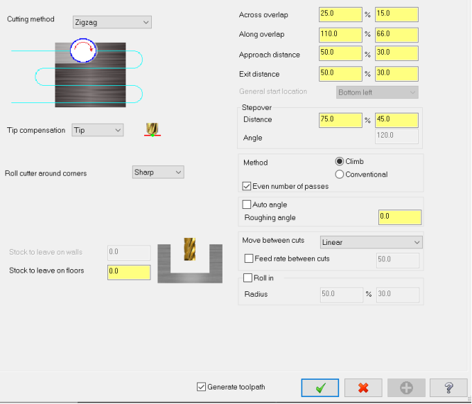
Figure 2 records the principal cutting data used for the initial datum-generating operation. A 60 mm face mill was programmed at 1000 rpm with a feed rate of 350 mm/min and a plunge rate of 100 mm/min. These conservative settings were appropriate for the first workshop trial because the primary objective was to obtain a stable reference plane and verify machine motion. The operation therefore prioritized reliable stock removal and low risk of overload rather than maximum material-removal rate.
Figure 3. Original face-milling strategy: zigzag path with 25% transverse overlap.
The zigzag strategy shown in Figure 3 was selected to cover the complete top surface without repeated rapid repositioning. The 25% overlap reduced the possibility of uncut strips between adjacent passes and produced a continuous planar reference. However, reversal at the ends of successive passes changes the instantaneous feed direction and may leave visible transition marks. This observation is relevant to the final surface condition discussed in Section 3, where the machined faces exhibited nonuniform cutter traces.
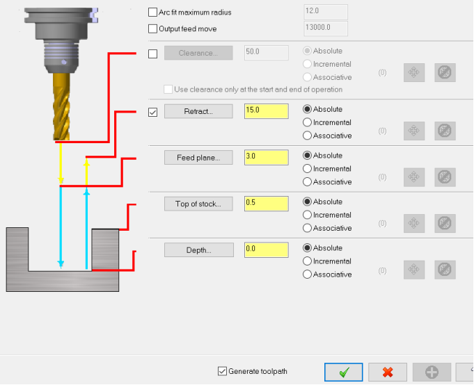
The linking parameters in Figure 4 defined the retract level, feed plane, stock top, and cutting depth. A 15 mm retract level and a 3 mm feed plane provided clearance above the workpiece and clamping elements, while the stock-top offset of 0.5 mm accounted for the initial material layer to be removed. Explicit definition of these Z levels was essential because the workpiece was held in a conventional vise; an incorrectly selected retract or approach level could have caused collision with the jaws or an excessive non-cutting motion.
Figure 4. Original linking parameters and vertical safety levels used in Mastercam.
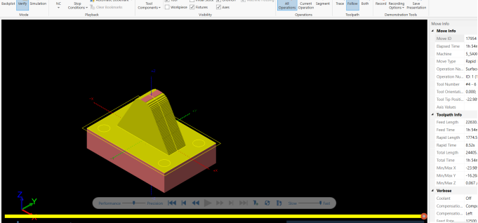
Figure 5. Toolpath verification for three-dimensional rough machining of the lug-type base.
For the lug-type base, the roughing region was bounded by a machining containment curve and processed using a surface-rough-pocket strategy. The verification view in Figure 5 shows that the cutter remained inside the intended material-removal domain and approached the raised lug from accessible directions. This step was important because the transition between the base plate and the inclined lug creates locally restricted tool access. The simulation confirmed that the roughing path removed the surrounding stock without intersecting the protected solid geometry.
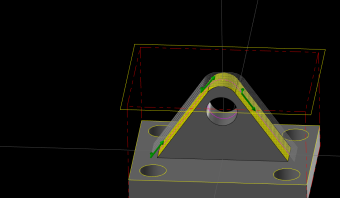
After roughing, a flowline finishing strategy was applied to the free-form lug surface (Figure 6). In contrast to the bulk-removal path, the finishing passes followed the local surface direction and used a smaller spacing between adjacent trajectories. The resulting path reduced abrupt changes in cutter engagement and was intended to improve continuity on the inclined region. The CAM image also demonstrates that the finishing operation was geometrically different from conventional two-dimensional contouring and therefore required direct verification of tool orientation, surface contact, and boundary behavior.
Figure 6. Flowline finishing path generated on the three-dimensional lug surface.
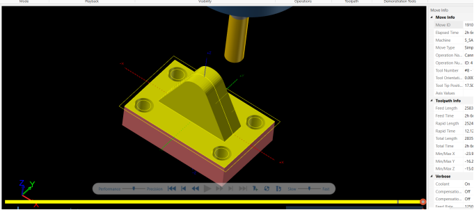
Figure 7. Complete Mastercam simulation of the lug-type component after all programmed operations.
The complete simulation in Figure 7 combined three-dimensional milling, hole making, and the remaining profile operations. Comparison between the simulated stock and the target model showed that the principal planar faces, lug geometry, hole locations, and external boundaries were reproduced before code transfer. This graphical verification did not prove dimensional accuracy, but it provided direct evidence that the machining sequence was complete, that no major residual stock remained in the programmed regions, and that the selected operations were mutually compatible.
The parameter set in Table 1 is reported as the original project data and was not re-optimized in the present work. Its role was to provide a reproducible baseline for evaluating the consistency between the CAM plan and the actual workshop implementation.
Table 1. Machining parameters retained from the original CAM project.

Operation

Tool

Spindle speed (rpm)

Feed rate (mm/min)

Principal CAM setting

Face milling

Face mill D60

1000

350

Zigzag; 25% overlap

Spot drilling

Spot drill D5

1000

90

G81-type cycle

Drilling for M5

Drill D4.2

1200

144

Depth referenced from stock top

Drilling for M8

Drill D6.8

CAM project value

CAM project value

Followed by tapping

Threading

M5 and M8 taps

Pitch synchronized

Pitch synchronized

Rigid tapping cycle

3. Results and Discussion
Following CAM verification, the generated NC programs were implemented on the selected machining system. This stage was used to examine whether the digital process plan could be transferred to the workshop without changing the established datum logic, operation sequence, or tool-access strategy.
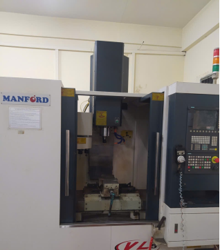
The verified toolpaths were post-processed and transferred to a Manford CNC vertical milling machine. The machine axes were referenced, the work offset was established from the machined datum plane and a side surface, and the aluminum blank was clamped in a standard vise. Tool lengths and diameters were entered into the controller before dry-run and single-block verification. This procedure maintained consistency between the coordinate system used in Mastercam and the actual workpiece location on the machine.
Figure 8. Manford CNC milling machine used for the workshop implementation.
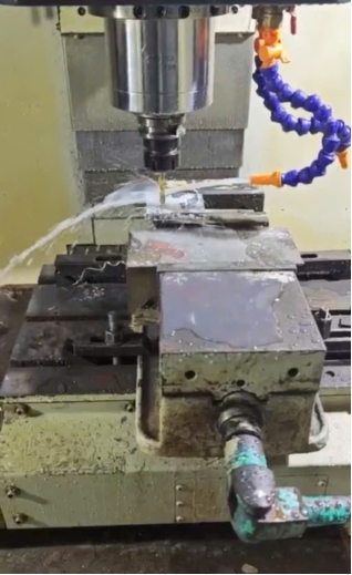
The use of a conventional three-axis machining center was sufficient for the investigated components because all features could be reached through sequential planar and three-dimensional operations. The machine configuration also made the study representative of small and medium workshops, where general-purpose CNC equipment and standard workholding are more accessible than dedicated multi-axis systems.
The experimental implementation was then evaluated for the two component variants, which differed substantially in geometric complexity and therefore required different combinations of planar and three-dimensional milling operations.
Figure 9. Actual machining of the plate-type pneumatic-cylinder base.
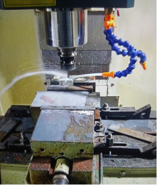
Figure 9 shows the machining of the plate-type base. The broad upper face was first milled to establish the principal datum, after which the hole pattern and remaining planar features were produced from the same coordinate framework. Maintaining a common datum minimized cumulative repositioning error between face milling and hole making. The compact geometry allowed the vise jaws to support the blank over a relatively large area, which limited visible movement during cutting.
The lug-type component required a more complex sequence because its inclined and raised surfaces could not be completed by two-dimensional operations alone. As shown in Figure 10, the workpiece remained clamped while the cutter generated the three-dimensional lug profile. The experimental setup confirms that the simulated accessibility was achievable on the real machine. Nevertheless, the long local tool engagement around the lug and the directional changes of the finishing path increased sensitivity to cutter marks and local vibration.
The correspondence between the digital models, CAM simulations, and finished components was assessed by comparing the programmed feature set with the geometry obtained in the workshop trials.
Figure 10. Actual machining of the lug-type pneumatic-cylinder base.
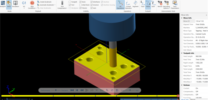
Figure 11. Final CAM-simulated geometry of the plate-type component.
The final simulation in Figure 11 verifies the complete machining sequence for the plate-type component before NC-code transfer. The simulated part contains the required external contour and the full distribution of large and small holes, indicating that the facing, drilling, and tapping operations were referenced to a consistent work coordinate system. The absence of visible residual stock in the simulated model also confirms that the programmed toolpaths reached the intended machining boundaries. This verification was essential because an incorrect hole-selection order, tool offset, or Z-level could otherwise lead to omitted features, excessive cutting, or collision during the workshop trial.
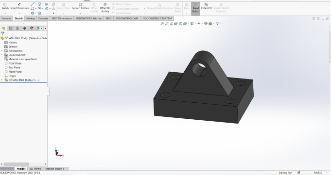
Figure 12. Original three-dimensional model of the lug-type component.
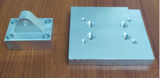
Figure 12 defines the target geometry of the lug-type component and therefore provides the reference for evaluating the CAM and machining results. Its principal features include a rectangular base, four mounting holes, an inclined central lug, and a transverse through-hole. Compared with the plate-type part, the inclined faces and curved transition around the lug require three-dimensional roughing and finishing rather than only planar milling and drilling. The model was consequently used to check cutter accessibility, preserve material around the lug, and establish a continuous finishing path before the corresponding component was machined.
Figure 13. Completed aluminum components produced in the workshop trial.

The completed parts in Figure 13 reproduce the main geometry represented by the digital models in Figures 11 and 12. For the plate-type component, the external rectangular form, central recessed region, and distributed hole pattern are clearly present. For the lug-type component, the raised inclined support and its through-hole were successfully generated together with the base mounting holes. This correspondence provides the strongest result of the study: the CAM sequence was not limited to graphical verification but was transferred into two physically machined component variants.
Visual inspection also revealed the limitations of the first implementation. Cutter marks remained visible on several planar and three-dimensional surfaces, and the finish was not uniform around the lug transition. The original project reported that the basic dimensions and hole locations were adequate for assembly-oriented trials, but it did not provide repeated coordinate measurements, a quantified roughness dataset, or pressure-leak testing. Consequently, the experimental evidence supports process feasibility and geometric reproduction, whereas compliance with final functional tolerances and sealing requirements cannot yet be claimed.
Table 2. Evidence obtained from the CAM-to-machining implementation.

Evaluation item

Observed result

Interpretation

CAM completeness

Face milling, 3D roughing/finishing, drilling, and tapping were simulated

The planned operation chain was complete before post-processing

Machine implementation

Both component variants were physically machined

The NC programs were executable on the available three-axis machine

Geometric correspondence

Principal profiles, lug geometry, and hole patterns were reproduced

The digital models and finished products were qualitatively consistent

Surface condition

Visible tool marks and local nonuniform finish remained

Finishing parameters and path transitions require further optimization

Dimensional validation

Basic workshop checks only

Full tolerance capability remains unverified

Functional validation

No pressure or leak test reported

Service suitability cannot yet be established

Taken together, the simulation and workshop results provide an integrated assessment of the proposed process-planning route and clarify both its practical value and its current limitations. Therefore, the reported outcome establishes workflow executability and qualitative geometric correspondence only. It does not establish dimensional capability, geometric-tolerance compliance, surface-quality conformity, thread integrity, or pneumatic sealing performance.
The manufacturing trial demonstrates that CAM planning and physical implementation should be evaluated as one continuous process chain. The most important contribution is the documented correspondence between the original Mastercam operations (Figures 2-7) and the two machined products (Figures 8-12). Establishing the broad base plane first provided a stable reference for subsequent hole making and three-dimensional finishing, while operation-by-operation simulation reduced the risk of incomplete material removal or collision before code transfer.
The face-milling parameters were conservative for aluminum and were appropriate for an initial feasibility trial. Nevertheless, the visible marks on the finished products indicate that successful simulation alone does not guarantee surface integrity. The zigzag reversal points, finishing-path spacing, local engagement around the lug, tool condition, and fixture-machine compliance may all have contributed to the observed surface traces. Future work should therefore optimize the finishing parameters using measured roughness and dimensional deviation rather than relying exclusively on visual assessment.
The choice of a standard vise was suitable for the compact prismatic blank, but it should not be generalized to all pneumatic-cylinder bases. Irregular castings or thin-walled variants may require profile-matching jaws, modular supports, pneumatic actuation, or flexible segmented clamping. The uploaded fixture studies demonstrate that distributed contact and reduced unsupported span can improve repeatability and limit deformation. These concepts can be incorporated into a future production fixture after the component family and batch size are defined.
Material substitution is the most important limitation of the present experiment. The aluminum trial confirmed tool accessibility and NC-program logic, but it did not reproduce the stiffness, damping, hardness, or wear behavior of gray cast iron. Therefore, the statement that the aluminum part is suitable for temporary assembly is reasonable, whereas claims concerning pressure retention, fatigue durability, or production conformity would be unsupported. A complete validation must machine the specified material or provide an engineering requalification of the substitute material.
The study also highlights the distinction between CAM verification and process validation. Graphical simulation can identify toolpath discontinuities, overtravel, and collision risk, but it cannot independently establish surface roughness, form error, thread quality, or leak tightness. Those quantities require calibrated measurements. Future experiments should include a coordinate-measuring-machine inspection of hole positions and perpendicularity, surface profilometry on the sealing and mounting faces, thread-gauge inspection, repeated machining trials, and pneumatic leak testing under the intended working pressure.
4. Conclusions
This study established and experimentally implemented a complete CAD/CAM-to-machining workflow for two pneumatic-cylinder-base variants. The proposed route linked functional geometry to a unified A-B-C datum system, organized the operations according to feature dependency, and translated the resulting plan into verified Mastercam toolpaths for face milling, contour and pocket milling, three-dimensional roughing and finishing, drilling, tapping, and chamfering. The successful transfer of the NC programs to a Manford three-axis CNC machining center demonstrates that the workflow is technically feasible using general-purpose equipment and conventional workholding commonly available in small and medium manufacturing workshops.
The principal result is the demonstrated correspondence among the CAD models, CAM simulations, and physically machined components. For the predominantly prismatic base, a common datum framework enabled the planar features and hole pattern to be produced within one consistent coordinate system. For the lug-type base, the combination of bounded three-dimensional roughing and flowline finishing provided adequate tool access to the inclined lug and its transition surfaces. Operation-by-operation simulation further confirmed toolpath completeness, protected the intended solid geometry, and reduced the risk of residual stock, omitted features, and collision before code transfer. These findings show that the value of CAM in this application extends beyond NC-code generation and lies primarily in the systematic verification of the entire process chain.
The experimental evidence nevertheless supports process feasibility rather than full production qualification. Visible cutter marks and locally nonuniform finish indicate that the initial parameter set and finishing strategies require further optimization. In addition, the use of aluminum instead of the initially specified gray cast iron means that the present trial does not establish equivalence in stiffness, damping, wear behavior, fatigue resistance, or sealing performance. The absence of repeated dimensional measurements, quantified surface-roughness data, thread-gauge inspection, and pressure-leak testing also prevents definitive claims regarding compliance with functional tolerances. Accordingly, the conclusions are limited to the technical feasibility and reproducible structure of the integrated process chain and should not be interpreted as evidence of production readiness or service qualification.
Future work should therefore combine the proposed process-planning framework with systematic metrology and parameter optimization. Recommended validation includes coordinate-measuring-machine inspection of hole position, perpendicularity, and datum relationships; surface profilometry of mounting and sealing faces; repeated machining trials for statistical repeatability; thread verification; and pneumatic leak testing at the intended operating pressure. Machining trials using the specified production material should also be conducted, together with optimization of finishing-path spacing, spindle speed, feed per tooth, and local tool engagement. With these extensions, the present application-oriented workflow can provide a reproducible basis for industrial process qualification and for the manufacturing of related pneumatic and mechanical support components.
Abbreviations

CAD

Computer-Aided Design

CAM

Computer-Aided Manufacturing

CNC

Computer Numerical Control

NC

Numerical Control

FEA

Finite Element Analysis

Author Contributions
Tran Thanh Tung: Conceptualization, Data curation, Formal Analysis, Investigation, Methodology, Project administration, Software, Supervision, Validation, Visualization, Writing – original draft, Writing – review & editing
Nguyen Thi Anh: Methodology, Writing – review & editing
Nguyen Xuan Quynh: Investigation, Resources, Validation, Writing – review & editing
Tran Vu Minh: Conceptualization, Validation
Data Availability Statement
The data supporting the outcome of this research work has been reported in this manuscript. Additional CAM files and workshop records are available from the corresponding author upon reasonable request.
Conflicts of Interest
The authors declare no conflicts of interest.
References
[1] Y. Altintas, Manufacturing Automation: Metal Cutting Mechanics, Machine Tool Vibrations, & CNC Design, 2nd ed. Cambridge, U. K.: Cambridge University Press, 2012.
[2] Mali, Rahul A., T. V. K. Gupta, and J. Ramkumar. "A comprehensive review of free-form surface milling–Advances over a decade." Journal of Manufacturing Processes 62 (2021): 132-167.
[3] Sujuan, W., Tao, Z., Bowen, H. et al. Analytical model for the prediction of milling forces: a review. Int J Adv Manuf Technol 134, 1015–1041 (2024).
[4] N. T. Anh and T. T. Tung, “Cutting force prediction in end milling processes: Analytical models & applications, ” Applications in Engineering Science, vol. 23, art. 100250, 2025,
[5] T. T. Tung, N. T. Anh, and T. V. Minh, “Design and development of a prototype 3-axis CNC wood carving machine,” International Journal of Advanced Technology and Engineering Exploration, vol. 12, no. 125, pp. 528-541, 2025,
[6] T. V. Minh, N. X. Quynh, N. T. Anh, and T. T. Tung, “Design and experimental study of a 4-axis CNC laser engraving machine,” Journal of Engineering Sciences, vol. 54, no. 4, pp. 272-287, 2026,
[7] N. T. Anh, N. X. Quynh, and T. T. Tung, “A milling technique for the fabrication of mechanical parts with thin-walled ribs,” Engineering, Technology & Applied Science Research, vol. 15, no. 4, pp. 24815-24819, 2025,
[8] T. T. Tung, N. X. Quynh, and T. V. Minh, “Experimental optimization of cutting parameters in flat-surface end milling using the Taguchi-desirability approach,” Engineering, Technology & Applied Science Research, vol. 16, no. 3, pp. 36693-36699, 2026,
[9] H. Liu, C. Wang, T. Li, et al., “Fixturing technology and system for thin-walled parts machining: A review, ” Frontiers of Mechanical Engineering, vol. 17, art. 55, 2022,
[10] Manafi, D., and Mohammad Javad Nategh. "Integrating the setup planning with fixture design practice by concurrent consideration of machining and fixture design principles." International Journal of Production Research 59, no. 9 (2021): 2647-2666,
[11] S. Meng, W. Fan, X. Wang, et al., “Intelligent design of reconfigurable flexible assembly fixture for aircraft panels based on smart composite jig model and knowledge graph,” Journal of Engineering Design, vol. 36, no. 5-6, pp. 672-706, 2025,
[12] T. T. Tung, N. T. Anh, N. X. Quynh, and T. V. Minh, “Development of a machining allowance model for rectangular pocket milling operations,” Revista de Ciencias Tecnológicas, vol. 9, no. 3, art. e498, 2026,
[13] He, Keyan, Huajie Hong, Renzhong Tang, and Junyu Wei. "Analysis of multi-objective optimization of machining allowance distribution and parameters for energy saving strategy." Sustainability 12, no. 2 (2020): 638,
[14] Brillinger, Markus, Marcel Wuwer, Muaaz Abdul Hadi, and Franz Haas. "Energy prediction for CNC machining with machine learning." CIRP Journal of Manufacturing Science and Technology 35 (2021): 715-723,
[15] Balogun, Vincent Aizebeoje, and Paul Tarisai Mativenga. "Modelling of direct energy requirements in mechanical machining processes." Journal of Cleaner Production 41 (2013): 179-186,
[16] J. H. Navarro-Devia, Y. Chen, D. V. Dao, and H. Li, “Chatter detection in milling processes—A review on signal processing and condition classification,” The International Journal of Advanced Manufacturing Technology, vol. 125, pp. 3943-3980, 2023,
[17] G. Kant and K. S. Sangwan, “Predictive modelling and optimization of machining parameters to minimize surface roughness using artificial neural network coupled with genetic algorithm,” Procedia CIRP, vol. 31, pp. 453-458, 2015,
[18] T. T. Tung and T. V. Minh, “Development of a prototype fractal vise,” International Journal of Mechanical Engineering and Robotics Research, vol. 14, no. 1, pp. 10-15, 2025,
[19] Anh, Nguyen Thi, and Tran Thanh Tung. "Development of Flexible Clamping Devices for Precision Workholding of Irregular and Thin-Walled Workpieces." environments 21: 25,
[20] Anh, Nguyen Thi, and Tran Thanh Tung. "Methodical approach to fixture design in the milling of thin-walled mechanical components." Results in Engineering (2025): 106518,
[21] Naeem, Armghan, Riffat Asim Pasha, and Muhammad Muneeb. "A novel milling fixture pallet system for production growth of alligator forceps: Design, manufacturing, and testing." Results in Engineering 16 (2022): 100668,
[22] P. S. Barve, Y. V. Deshpande, D. R. Zanwar, et al., “Development of an innovative assembly fixture for machining synchronization of multi fuse parts on vertical machining center and productivity enhancement,” Journal of Scientific & Industrial Research, vol. 83, no. 11, pp. 1172-1183, 2024,
[23] S. Liu, S. Afazov, A. Becker, et al., “Machining error prediction scheme aided smart fixture development in machining of a Ti6Al4V slender part,” Proceedings of the Institution of Mechanical Engineers, Part B: Journal of Engineering Manufacture, vol. 237, no. 10, pp. 1509–1517, 2023,
[24] N. T. Anh and T. T. Tung, “Development and validation of finite element model of milling thin-walled part,” Applications in Engineering Science, vol. 25, art. 100285, 2026,
[25] Karimi, Behnam, and Yusuf Altintas. "Hybrid modeling of position-dependent dynamics of thin-walled parts using shell elements for milling simulation." Journal of Manufacturing Science and Engineering 144, no. 8 (2022): 081014,
[26] Ge, Guangyan, Yukun Xiao, Xiaobing Feng, and Zhengchun Du. "An efficient prediction method for the dynamic deformation of thin-walled parts in flank milling." Computer-Aided Design 152 (2022): 103401,
[27] Jia, Zhenyuan, Xiaohong Lu, Han Gu, Feixiang Ruan, and Steven Y. Liang. "Deflection prediction of micro-milling Inconel 718 thin-walled parts." Journal of Materials Processing Technology 291 (2021): 117003.
[28] X. Gao, et al., “Research on optimization of micro-milling process for curved thin wall structure,” Precision Engineering, vol. 73, pp. 296-312, 2022,
[29] N. T. Anh and T. T. Tung, “Finite element and experimental investigation of up- and down-milling in thin-wall machining,” Progress in Engineering Science, vol. 3, art. 100209, 2026,
[30] Xiang, Junfeng, and Jie Yi. "Deformation mechanism in wax supported milling of thin-walled structures based on milling forces stability." CIRP Journal of Manufacturing Science and Technology 32 (2021): 356-369,
[31] Zhan, Danian, Dawei Lu, Wenxiang Gao, Haojie Wei, and Yuwen Sun. "Chatter detection in thin-wall milling based on multi-sensor fusion and dual-stream residual attention CNN." Machines 12, no. 8 (2024): 559,
[32] Kurpiel, Szymon, Krzysztof Zagórski, Jacek Cieślik, and Krzysztof Skrzypkowski. "Investigation of selected surface topography parameters and deformation during milling of vertical thin-walled structures from titanium alloy Ti6Al4V." Materials 16, no. 8 (2023): 3182,
[33] G Wu, Ge, Xuanyu Mao, Wencheng Pan, Guangxian Li, and Songlin Ding. "The machinability of titanium alloy thin-wall parts in cooling minimum quantity lubrication (CMQL) environments." The International Journal of Advanced Manufacturing Technology 129, no. 7 (2023): 2875-2895,
[34] Y. V. Srinivasa and M. S. Shunmugam, “Mechanistic model for prediction of cutting forces in micro end-milling and experimental comparison,” International Journal of Machine Tools and Manufacture, vol. 67, pp. 18-27, 2013,
[35] CNC Software, Inc., Mastercam 2022 Documentation. Tolland, CT, USA: CNC Software, Inc., 2021.
[36] C. A. J. S. Taipe and E. H. Cayo, “Design and prototyping of a 4-axis CNC machine for the manufacturing of small accessories,” in Proceedings of the 10th International Conference on Mechatronics and Robotics Engineering, 2024, pp. 5-9,
[37] ASM International, ASM Handbook, Volume 1: Properties & Selection—Irons, Steels, & High–Performance Alloys. Materials Park, OH, USA: ASM International, 1990.
[38] J. R. Davis, Ed., Aluminum and Aluminum Alloys. Materials Park, OH, USA: ASM International, 1993.
Cite This Article
  • APA Style

    Tung, T. T., Anh, N. T., Quynh, N. X., Minh, T. V. (2026). Design and Experimental Implementation of a CNC Milling Process for a Pneumatic Cylinder Base. Industrial Engineering, 10(2), 36-48. https://doi.org/10.11648/j.ie.20261002.11

    Copy | Download

    ACS Style

    Tung, T. T.; Anh, N. T.; Quynh, N. X.; Minh, T. V. Design and Experimental Implementation of a CNC Milling Process for a Pneumatic Cylinder Base. Ind. Eng. 2026, 10(2), 36-48. doi: 10.11648/j.ie.20261002.11

    Copy | Download

    AMA Style

    Tung TT, Anh NT, Quynh NX, Minh TV. Design and Experimental Implementation of a CNC Milling Process for a Pneumatic Cylinder Base. Ind Eng. 2026;10(2):36-48. doi: 10.11648/j.ie.20261002.11

    Copy | Download

  • @article{10.11648/j.ie.20261002.11,
      author = {Tran Thanh Tung and Nguyen Thi Anh and Nguyen Xuan Quynh and Tran Vu Minh},
      title = {Design and Experimental Implementation of a CNC Milling Process for a Pneumatic Cylinder Base},
      journal = {Industrial Engineering},
      volume = {10},
      number = {2},
      pages = {36-48},
      doi = {10.11648/j.ie.20261002.11},
      url = {https://doi.org/10.11648/j.ie.20261002.11},
      eprint = {https://article.sciencepublishinggroup.com/pdf/10.11648.j.ie.20261002.11},
      abstract = {Pneumatic-cylinder bases contain planar interfaces, stepped regions, hole patterns, and threaded features whose relative accuracy directly affects assembly and sealing performance. This study develops and experimentally implements a milling-oriented process-planning framework for a representative cylinder-base component. The workflow links functional requirements to datum selection, operation sequencing, cutting-tool selection, computer-aided manufacturing (CAM) programming, toolpath verification, and shop-floor execution. The component was modeled and programmed in Mastercam 2022. The adopted sequence comprised face milling, contour and pocket milling, center drilling, drilling, tapping, chamfering, and final inspection. A D60 face mill, end mills, 4.2 and 6.8 mm drills, spot drill, chamfer tool, and M5/M8 taps were used. The NC programs were verified through graphical simulation before machining on a Manford CNC machining center. An aluminum blank available in the workshop was used to demonstrate the process, although the original design was intended for gray cast iron. The completed component reproduced the required overall geometry and hole arrangement and was suitable for assembly trials. Visual inspection, however, revealed cutter marks and a surface condition inferior to the original specification; therefore, sealing performance and long-term load capacity were not claimed. The results show that a design-to-CAM process chain can reduce programming ambiguity and provide a reproducible route for low-volume production, while also demonstrating that material substitution and the absence of quantitative surface-metrology data must be explicitly considered when assessing manufacturing conformity. Accordingly, the experimental evidence should be interpreted as verification of workflow implementation and qualitative geometric feasibility, not as quantitative qualification of dimensional accuracy, surface integrity, or pneumatic function.},
     year = {2026}
    }
    

    Copy | Download

  • TY  - JOUR
    T1  - Design and Experimental Implementation of a CNC Milling Process for a Pneumatic Cylinder Base
    AU  - Tran Thanh Tung
    AU  - Nguyen Thi Anh
    AU  - Nguyen Xuan Quynh
    AU  - Tran Vu Minh
    Y1  - 2026/08/17
    PY  - 2026
    N1  - https://doi.org/10.11648/j.ie.20261002.11
    DO  - 10.11648/j.ie.20261002.11
    T2  - Industrial Engineering
    JF  - Industrial Engineering
    JO  - Industrial Engineering
    SP  - 36
    EP  - 48
    PB  - Science Publishing Group
    SN  - 2640-1118
    UR  - https://doi.org/10.11648/j.ie.20261002.11
    AB  - Pneumatic-cylinder bases contain planar interfaces, stepped regions, hole patterns, and threaded features whose relative accuracy directly affects assembly and sealing performance. This study develops and experimentally implements a milling-oriented process-planning framework for a representative cylinder-base component. The workflow links functional requirements to datum selection, operation sequencing, cutting-tool selection, computer-aided manufacturing (CAM) programming, toolpath verification, and shop-floor execution. The component was modeled and programmed in Mastercam 2022. The adopted sequence comprised face milling, contour and pocket milling, center drilling, drilling, tapping, chamfering, and final inspection. A D60 face mill, end mills, 4.2 and 6.8 mm drills, spot drill, chamfer tool, and M5/M8 taps were used. The NC programs were verified through graphical simulation before machining on a Manford CNC machining center. An aluminum blank available in the workshop was used to demonstrate the process, although the original design was intended for gray cast iron. The completed component reproduced the required overall geometry and hole arrangement and was suitable for assembly trials. Visual inspection, however, revealed cutter marks and a surface condition inferior to the original specification; therefore, sealing performance and long-term load capacity were not claimed. The results show that a design-to-CAM process chain can reduce programming ambiguity and provide a reproducible route for low-volume production, while also demonstrating that material substitution and the absence of quantitative surface-metrology data must be explicitly considered when assessing manufacturing conformity. Accordingly, the experimental evidence should be interpreted as verification of workflow implementation and qualitative geometric feasibility, not as quantitative qualification of dimensional accuracy, surface integrity, or pneumatic function.
    VL  - 10
    IS  - 2
    ER  - 

    Copy | Download

Author Information