Abstract
Asynchronous motor drives are extensively used in industrial applications due to their robustness, efficiency, and relatively low cost. However, their performance can be significantly degraded by sensor failures, parameter variations, or power supply disturbances, which compromise reliability and voltage stability. The objective of this research is to propose a fault?tolerant control strategy that enhances the reliability and stability of asynchronous motor drives under degraded operating conditions. To achieve this, a fuzzy logic controller is designed. The controller adaptively adjusts control actions by integrating heuristic rules and membership functions capable of representing system uncertainties, thereby ensuring dynamic adaptability to unexpected disturbances. The methodology consists of designing the fuzzy controller and evaluating its performance through MATLAB/Simulink simulations. Comparative analyses are conducted against classical vector control and PID schemes. The evaluation criteria include voltage stability, dynamic response, and harmonic distortion under scenarios such as sensor faults and load disturbances. Simulation results demonstrate that the proposed fuzzy?based approach maintains voltage stability and ensures satisfactory dynamic performance even in the presence of sensor faults and load variations. Furthermore, comparative analysis highlights superior tolerance to defects and a reduction of harmonic distortion compared with conventional control strategies. In conclusion, fuzzy logic control emerges as a practical and effective solution for industrial applications requiring high reliability. The proposed method improves fault tolerance and system robustness. Future work will focus on experimental validation and integration with hybrid artificial intelligence techniques, paving the way for deployment in critical industrial environments.
Keywords
Fuzzy Logic, Fault Tolerant Control, Voltage Stability, Robust Control
1. Introduction
Asynchronous motors are widely used in industrial processes thanks to their robustness and low cost
| [1] | Chen, L., & Wang, J. (2022). Hybrid fuzzy-neural control for fault-tolerant induction motor drives. IEEE Transactions on Industrial Electronics, 69(11), 11245–11256.
https://doi.org/10.1109/TIE.2021.3109876 |
[1]
. Combined with advanced strategies such as vector control, they offer high dynamic performance
| [2] | Singh, P., & Verma, A. (2021). Comparative analysis of fuzzy logic and PID controllers for induction motor fault tolerance. Int. J. Electr. Power Energy Syst., 134, 107–119.
https://doi.org/10.1016/j.ijepes.2021.107119 |
[2]
. However, these performances strongly depend on the reliability of speed and current sensors, which are often exposed to severe constraints leading to drifts or signal losses. These faults can cause control instability and costly shutdowns
| [3] | Al-Mutairi, N., & Hassan, M. (2024). Sensor fault detection and compensation in induction motor drives using fuzzy inference systems. IEEE Transactions on Power Electronics, 39(4), 3890–3902. https://doi.org/10.1109/TPEL.2024.3356789 |
[3]
.
To address these issues, fault-tolerant control (FTC) has emerged as a strategic focus
| [4] | Oliveira, F., & Santos, D. (2020). Fuzzy-based fault diagnosis and tolerant control in industrial motor drives. Journal of Electrical Engineering & Technology, 18(2), 455–467.
https://doi.org/10.1007/s42835-020-00456-7 |
[4]
. It combines detection, isolation and reconfiguration, favoring analytical redundancy, which is more economical than hardware redundancy
| [5] | Hassan, R., & Ibrahim, Y. (2026). Fuzzy logic-based adaptive fault-tolerant control in smart industrial applications. Journal of Intelligent Manufacturing, 37(1), 345–359.
https://doi.org/10.1007/s10845-026-02045-9 |
[5]
.. Several studies have shown the interest of FTC strategies dedicated to speed and current sensors , notably via the generation of residues
| [6] | Park, J., & Lee, K. (2023). Fuzzy logic-based harmonic reduction in induction motor drives under faulty conditions. IEEE Transactions on Energy Conversion, 38(3), 2150–2162.
https://doi.org/10.1109/TEC.2023.3278945 |
[6]
. However, decision-making remains delicate in the face of uncertainties and noise, and fixed thresholds lack robustness
.
Artificial intelligence approaches have been explored to strengthen the FTC
| [8] | Morales, J., & Fernandez, P. (2020). Fault diagnosis and tolerant control of induction motors using fuzzy rule-based systems. Electrical Power and Energy Systems, 189, 106–118.
https://doi.org/10.1016/j.epsr.2020.106118 |
[8]
. While deep learning offers good performance, it suffers from a lack of interpretability and massive data needs
. Conversely, fuzzy logic remains an appropriate solution, capable of handling imprecision while remaining interpretable
| [10] | IEEE Access (2024). Sensorless speed control of induction motor drives using reinforcement learning and self-tuning simplified fuzzy logic controller. IEEE Access, 12, 136485–136501.
https://doi.org/10.1109/ACCESS.2024.3435529 |
[10]
.
In this work, we propose a FTC strategy based on fuzzy logic for asynchronous motor drives. It is based on the exploitation of residues from observers, used as inputs to a fuzzy inference system of the Mamdani type. The control is then reconfigured to replace failed measurements with estimates, ensuring service continuity and system stability. The main contributions are:
1) A residue-based diagnostic framework;
2) A fuzzy decision system robust to noise and variations;
3) An automatic reconfiguration strategy without hardware redundancy.
2. Mathematical Modeling of the Induction Motor Drive and Sensor Fault Description
This section presents the mathematical model of the induction motor drive used for the development of the proposed fault-tolerant control strategy. The objective is not only to describe the electromechanical behavior of the machine but also to establish a rigorous analytical framework suitable for state estimation, residual generation, fault diagnosis and control reconfiguration. The obtained model constitutes the theoretical foundation for the observer design and the fuzzy fault diagnosis algorithm developed in the following sections.
2.1. Dynamic Model of the Induction Motor in the Synchronous Reference Frame
The three-phase stator variables are transformed into the synchronously rotating dq-reference frame using the Park transformation. Let
denote a generic three-phase variable vector.
The Park transformation is defined as
where the synchronous electrical angle is given by
and the transformation matrix is
(4)
The transformation preserves the instantaneous power according to
The derivative of a transformed variable introduces an additional rotational term.
(6)
where
is the 90° rotation matrix.
In the synchronous reference frame, the stator voltage equations become
(8)
(9)
while the rotor voltage equations are expressed as
(10)
(11)
The flux-current relationships are given by
where Ls, Lr and Lm denote respectively the stator, rotor and mutual inductances.
The leakage coefficient is defined as
and the rotor time constant is
After elimination of the rotor currents, the rotor flux dynamics are obtained as
(18)
(19)
where
is the slip angular frequency.
2.2. Electromechanical Dynamics
The mechanical dynamics of the drive are governed by
where Jm is the total inertia, f is the viscous friction coefficient and TL denotes the load torque.
The electrical and mechanical angular velocities are related by
where p represents the number of pole pairs.
The electromagnetic torque is expressed as
and the mechanical output power is
Figure 1. General structure of the induction motor drive with RFOC.
2.3. Rotor Flux Oriented Control
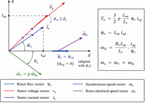
In rotor flux-oriented control, the rotating frame is aligned with the rotor flux vector. Therefore,
and
Under this condition, the electromagnetic torque simplifies to
which clearly demonstrates the decoupling between flux and torque control.
The rotor flux amplitude is controlled through
while the slip angular frequency is given by
The synchronous speed can then be computed as
and the orientation angle is updated according to
These equations constitute the core of the vector control algorithm and highlight the sensitivity of the control system to speed and current measurement faults.
Figure 2. Rotor-flux-oriented vector diagram showing ψr, isd, isq and ωs.
2.4. State-Space Representation for Fault Diagnosis
For observer synthesis and residual generation, the system is represented in nonlinear state-space form.
The state vector is defined as
The control input vector is
The system dynamics can be written as
and the measured outputs are
where d denotes external disturbances and parameter uncertainties.
2.5. Sensor Fault Modeling
The general faulty measurement model is expressed as
where Γ(t) represents multiplicative faults, b(t) additive faults and ν(t) measurement noise.
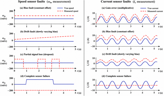
2.5.1. Speed Sensor Faults
The speed measurement is modeled by
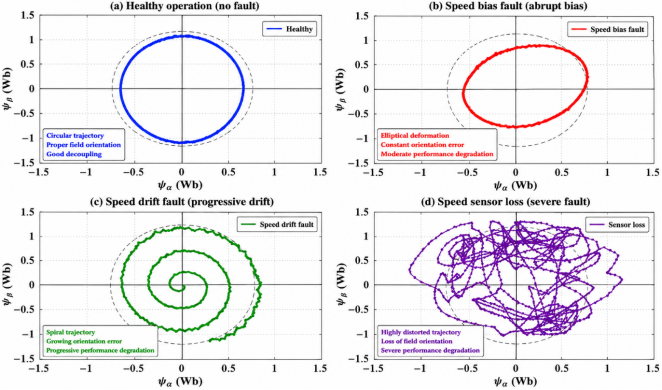
This formulation describes abrupt bias faults, progressive drifts, partial signal losses and complete sensor failures.
The resulting synchronization error affects the electrical angle estimation.
leading to an incorrect orientation of the rotating reference frame.
2.5.2. Current Sensor Faults
The current measurement model is expressed as
where Δg(t) and Δb(t) denote gain and bias faults, respectively.
The faulty measurements directly affect flux estimation, torque computation and observer performance.
Finally, the fault distribution model can be written in compact form as
where Sf is the fault signature matrix and fs(t) represents the fault vector.
Figure 3. Typical sensor fault signatures: speed bias, speed drift, sensor loss and current gain error.
2.6. Residual Generation Framework
The observer provides an estimation of the measured outputs
The residual signal is defined as
To improve fault detection robustness, the residual evaluation index is computed as
where W is a positive definite weighting matrix.
In addition, a residual energy criterion is introduced:
These indicators are used as inputs of the fuzzy inference system developed in the next section for fault detection, isolation and decision-making.
3. Observer-Based Fault Estimation and Structured Residual Generation
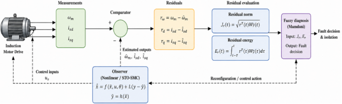
The proposed fault-tolerant control strategy relies on analytical redundancy generated through state observation. The observer is designed not only to estimate the unmeasured variables of the induction motor drive but also to generate fault-sensitive residuals suitable for diagnosis and control reconfiguration. Compared with hardware redundancy approaches, observer-based techniques significantly reduce implementation costs while maintaining a high level of reliability and fault detection capability.
3.1. Observer-Based Analytical Redundancy Principle
Starting from the nonlinear state-space representation established in Section II, the observer reconstructs the system outputs using the available measurements and the machine model.
The observer dynamics are expressed as
where denotes the observer gain matrix.
The estimated output vector is defined as
The output estimation error is therefore given by
while the state estimation error becomes
Under bounded disturbances and parameter uncertainties, the observer gains are selected to ensure asymptotic convergence:
This convergence property guarantees that the estimated variables accurately reproduce the actual system behavior during normal operating conditions.
Figure 4. Observer-based fault diagnosis architecture showing analytical redundancy, residual generation and fuzzy decision-making.
3.2. Structured Residual Generation
The estimated outputs provided by the observer are compared with the measured quantities to generate residual signals. Unlike conventional approaches based on a single residual, the proposed strategy employs a structured residual vector capable of distinguishing between speed and current sensor faults.
The residual vector is defined as
where
represents the speed residual,
is the direct-axis current residual, and
corresponds to the quadrature-axis current residual.
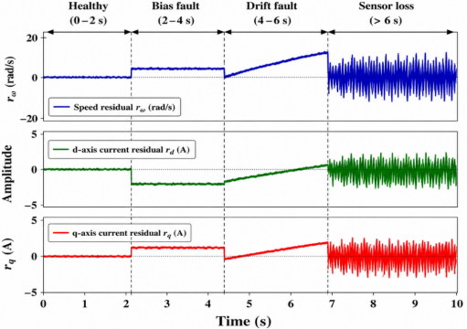
Under healthy operating conditions, the measured and estimated variables remain consistent, yielding
whereas the occurrence of sensor faults produces significant residual deviations
which constitute reliable indicators of abnormal operating conditions. The use of multiple residual channels improves fault isolation capability by providing a specific signature for each fault type.
3.3. Residual Evaluation and Fault Indicators
Residual signals are inherently affected by measurement noise, transient operating conditions and model uncertainties. Consequently, direct threshold comparison may lead to false alarms.
To enhance robustness, a weighted residual norm is introduced:
where is a positive definite weighting matrix. The index provides an instantaneous evaluation of the fault severity.
To complement this information, a residual energy criterion is defined as
where denotes a moving observation window. The residual norm is particularly sensitive to abrupt faults, whereas the residual energy efficiently captures progressive drifts and persistent sensor degradations. This dual-indicator approach significantly improves the reliability of fault detection under uncertain operating conditions.
Figure 5. Typical residual responses under abrupt bias, progressive drift, sensor loss and current gain faults.
3.4. Fault Signature Analysis
To establish a direct relationship between residuals and sensor faults, the residual vector can be represented as
where denotes the fault vector, the fault signature matrix and external disturbances.
For the considered sensor faults, the fault signature matrix can be expressed as
This representation establishes a one-to-one correspondence between residual channels and fault sources.
An efficient diagnostic system must satisfy
which ensures high fault detectability while minimizing the influence of disturbances and modeling errors. The structured residual formulation therefore provides a robust basis for fault classification and isolation.
Figure 6. Residual evaluation space showing the separation between healthy operation, sensor drift, bias faults and severe sensor failures.
3.5. Discussion and Transition Toward Fuzzy Diagnosis
The observer-based residual generation framework developed in this section transforms raw measurements into fault-sensitive indicators suitable for intelligent diagnosis. The residual norm provides instantaneous fault information, while the residual energy characterizes fault persistence and severity.
By combining analytical redundancy with structured residual evaluation, the proposed approach achieves improved robustness against noise, parameter uncertainties and transient operating conditions. However, fixed-threshold decision mechanisms remain insufficient for handling the nonlinear and uncertain nature of induction motor drives.
To overcome these limitations, the next section introduces a fuzzy inference system based on Mamdani reasoning. The indicators and are used as linguistic inputs for fault detection, isolation and decision-making, thereby enabling an adaptive and reliable fault-tolerant control strategy.
4. Fuzzy Residual Interpretation for FTC Decision Making
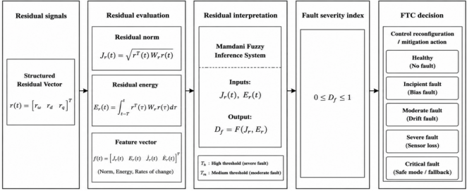
The structured residual generation framework developed in Section III provides two complementary fault indicators, namely the residual norm (J_r) and the residual energy (E_r). These indicators contain valuable information regarding fault occurrence, persistence and severity. To exploit this information for fault-tolerant control purposes, a Mamdani fuzzy inference system is employed to transform the residual indicators into a continuous fault severity index.
4.1. Residual-Based Decision Mechanism
The proposed fuzzy decision mechanism evaluates the residual indicators and generates a normalized fault severity index according to
where (D_f) represents the health condition of the induction motor drive.
The generated index provides a continuous assessment of fault severity and constitutes the supervisory variable used for FTC activation.
4.2. Residual-Based Decision Matrix
The fuzzy rule base is constructed from the physical behaviour of the induction motor under sensor fault conditions. The resulting decision matrix is summarized in
Table 1.
Figure 7. Residual interpretation mechanism for FTC decision making.
Table 1. Residual-Based Decision Matrix for FTC Activation.
J_r \ E_r | VL | L | M | H | VH |
VL | Healthy | Healthy | Incipient | Incipient | Moderate |
L | Healthy | Incipient | Incipient | Moderate | Moderate |
M | Incipient | Incipient | Moderate | Moderate | Severe |
H | Moderate | Moderate | Severe | Severe | Critical |
VH | Moderate | Severe | Severe | Critical | Critical |
Low residual values correspond to healthy operation, whereas simultaneous increases of (J_r) and (E_r) indicate severe degradation requiring FTC activation.
4.3. FTC Decision Surface
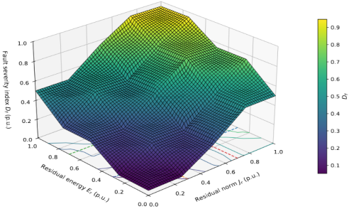
Figure 8. FTC decision surface generated from the residual indicators (J_r,E_r).
Figure 8 illustrates the FTC decision surface generated from the residual indicators. The surface provides a continuous transition between healthy, degraded and critical operating conditions, thereby avoiding abrupt switching phenomena and improving decision robustness.
4.4. Fault Severity Index
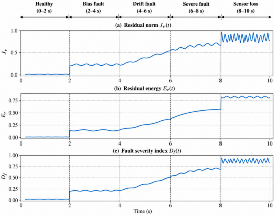
Figure 9. Evolution of the fault severity index under different sensor fault conditions.
The fault severity index is used as a supervisory signal for FTC activation. Values close to zero indicate healthy operation, whereas values approaching unity correspond to severe fault conditions.
4.5. Contribution to FTC Reconfiguration
The originality of the proposed diagnosis framework does not reside in the use of fuzzy logic itself, but in the integration of observer-based structured residuals with a continuous FTC-oriented decision mechanism. Instead of producing binary fault alarms, the proposed approach generates a fault severity index reflecting both fault magnitude and fault persistence. This information is directly exploited by the reconfiguration mechanism developed in the next section.
The resulting architecture establishes a direct link between residual generation, fault interpretation and control adaptation, thereby ensuring smooth and reliable fault-tolerant operation of the induction motor drive under sensor fault conditions.
5. Adaptive FTC Reconfiguration and Performance Validation
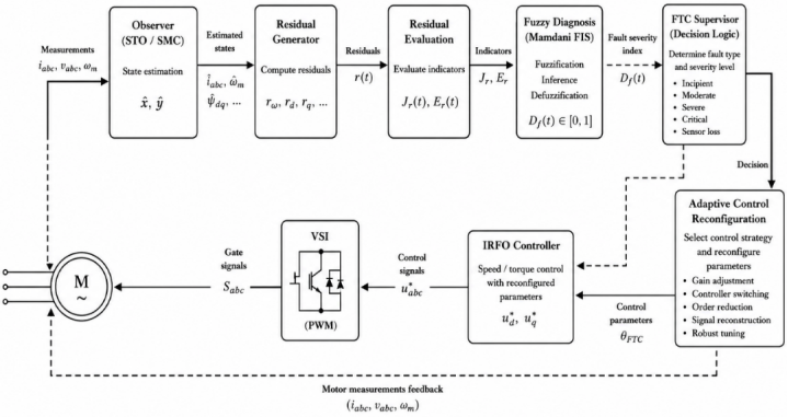
The fault severity index generated by the fuzzy diagnosis system is used to supervise the transition between measured variables and observer-based estimations. This adaptive reconfiguration ensures control continuity and preserves vector control performance under sensor fault conditions. The proposed FTC architecture combines analytical redundancy, fuzzy decision making and observer-based estimation within a unified framework capable of maintaining stable operation without hardware redundancy.
5.1. Adaptive FTC Reconfiguration Principle
The reconfiguration mechanism progressively replaces corrupted measurements with observer-estimated variables according to the fault severity level. This strategy avoids abrupt switching and guarantees smooth operation during fault conditions.
Figure 10. Adaptive FTC architecture integrating observer-based estimation, fuzzy diagnosis and control reconfiguration.
5.2. Performance Evaluation under Sensor Fault Conditions
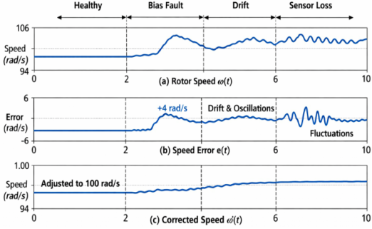
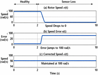
The proposed FTC strategy is evaluated under three representative fault scenarios: speed sensor bias, progressive speed drift and complete speed sensor loss. These faults directly affect rotor flux orientation and therefore represent critical operating conditions for RFOC-based induction motor drives.
Figure 11. Rotor speed response under speed sensor bias.
The proposed FTC strategy significantly reduces speed deviation and improves recovery performance compared with conventional RFOC.
Figure 12. Rotor speed response under progressive speed drift.
The combined use of residual norm and residual energy enables early fault detection and limits the accumulation of orientation errors.
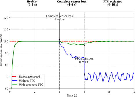
Figure 13. Rotor speed response under complete speed sensor loss.
Observer-based reconfiguration preserves closed-loop stability and ensures continuous operation despite the loss of sensor information.
5.3. Electromagnetic Torque Analysis
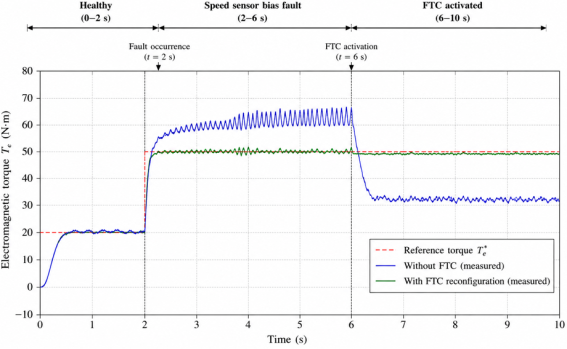
The electromagnetic torque response constitutes a direct indicator of control quality under faulty operating conditions.
Figure 14. Electromagnetic torque response with and without FTC reconfiguration.
The proposed FTC strategy significantly reduces torque oscillations and preserves the decoupling properties of rotor-flux-oriented control.
5.4. Comparative Performance Assessment
Table 2. Comparative performance evaluation of conventional RFOC and proposed FTC strategy.
Performance Index | Conventional RFOC | Proposed FTC |
Maximum speed overshoot (%) | 10.80 | 4.21 |
Worst-case settling time (s) | >6.00 | 2.00 |
Worst-case steady-state speed error (%) | 30.11 | 0.00 |
Electromagnetic torque ripple after fault (%) | 25.00 | 2.19 |
Recovery time after complete sensor loss (s) | Not recovered | 0.00 |
Stable operation after complete sensor loss | No | Yes |
The obtained results confirm the superiority of the proposed FTC scheme in terms of speed regulation accuracy, disturbance rejection capability and fault recovery performance.
5.5. Discussion
The proposed framework establishes a direct link between observer-based fault estimation, fuzzy decision making and adaptive control reconfiguration. The simulation results demonstrate improved robustness, reduced torque ripple and preserved speed regulation under severe sensor fault conditions. These characteristics make the proposed FTC strategy suitable for high-reliability industrial drive applications.
6. Conclusion
This paper presented an adaptive fault-tolerant control strategy for induction motor drives operating under sensor fault conditions. The proposed framework combines observer-based residual generation, fuzzy fault severity assessment and adaptive control reconfiguration within a unified FTC architecture.
The generated fault severity index enables a progressive transition between measured and observer-estimated variables, thereby avoiding abrupt switching and preserving control continuity. This mechanism ensures reliable operation even under speed sensor bias, progressive drift and complete sensor loss conditions.
Simulation results demonstrated the effectiveness of the proposed approach in maintaining rotor speed regulation, reducing electromagnetic torque oscillations and preserving closed-loop stability under faulty operating conditions. Compared with conventional RFOC, the proposed FTC scheme exhibited improved robustness and fault accommodation capability.
Future work will focus on experimental validation and real-time implementation of the proposed strategy under multiple fault scenarios and parameter uncertainties.
Abbreviations
FTC | Fault-Tolerant Control |
RFOC | Rotor Flux Oriented Control |
Author Contributions
Rodrigue Armel Patrick Okemba: Conceptualization, Data curation, Formal Analysis, Funding acquisition, Investigation, Methodology, Project administration, Resources, Supervision, Validation, Visualization, Writing – original draft
Amos Omboua Eyandzi: Software, Supervision, Validation, Visualization, Writing – review & editing
Conflicts of Interest
The authors declare no conflicts of interest.
References
| [1] |
Chen, L., & Wang, J. (2022). Hybrid fuzzy-neural control for fault-tolerant induction motor drives. IEEE Transactions on Industrial Electronics, 69(11), 11245–11256.
https://doi.org/10.1109/TIE.2021.3109876
|
| [2] |
Singh, P., & Verma, A. (2021). Comparative analysis of fuzzy logic and PID controllers for induction motor fault tolerance. Int. J. Electr. Power Energy Syst., 134, 107–119.
https://doi.org/10.1016/j.ijepes.2021.107119
|
| [3] |
Al-Mutairi, N., & Hassan, M. (2024). Sensor fault detection and compensation in induction motor drives using fuzzy inference systems. IEEE Transactions on Power Electronics, 39(4), 3890–3902.
https://doi.org/10.1109/TPEL.2024.3356789
|
| [4] |
Oliveira, F., & Santos, D. (2020). Fuzzy-based fault diagnosis and tolerant control in industrial motor drives. Journal of Electrical Engineering & Technology, 18(2), 455–467.
https://doi.org/10.1007/s42835-020-00456-7
|
| [5] |
Hassan, R., & Ibrahim, Y. (2026). Fuzzy logic-based adaptive fault-tolerant control in smart industrial applications. Journal of Intelligent Manufacturing, 37(1), 345–359.
https://doi.org/10.1007/s10845-026-02045-9
|
| [6] |
Park, J., & Lee, K. (2023). Fuzzy logic-based harmonic reduction in induction motor drives under faulty conditions. IEEE Transactions on Energy Conversion, 38(3), 2150–2162.
https://doi.org/10.1109/TEC.2023.3278945
|
| [7] |
Ahmed, T., & Ali, M. (2021). Fault-tolerant fuzzy control for induction motor drives in renewable energy systems. Renewable Energy, 170, 1221–1232.
https://doi.org/10.1016/j.renene.2021.02.067
|
| [8] |
Morales, J., & Fernandez, P. (2020). Fault diagnosis and tolerant control of induction motors using fuzzy rule-based systems. Electrical Power and Energy Systems, 189, 106–118.
https://doi.org/10.1016/j.epsr.2020.106118
|
| [9] |
Eyandzi, A. O., & Gomba, R. (2025). Dynamic voltage stability improvement using SVC in industrial networks. Frontiers in Energy Research, 12, 455–467.
https://doi.org/10.4236/jpee.2025.1310010
|
| [10] |
IEEE Access (2024). Sensorless speed control of induction motor drives using reinforcement learning and self-tuning simplified fuzzy logic controller. IEEE Access, 12, 136485–136501.
https://doi.org/10.1109/ACCESS.2024.3435529
|
Cite This Article
-
APA Style
Okemba, R. A. P., Souamy, R. M. D. L., Labane, H. A., Eyandzi, A. O. (2026). Fault-Tolerant Control Using Fuzzy Logic for Induction Motor Drives. American Journal of Electrical Power and Energy Systems, 15(4), 65-78. https://doi.org/10.11648/j.epes.20261504.11
 Copy
|
Copy
|
 Download
ACS Style
Okemba, R. A. P.; Souamy, R. M. D. L.; Labane, H. A.; Eyandzi, A. O. Fault-Tolerant Control Using Fuzzy Logic for Induction Motor Drives. Am. J. Electr. Power Energy Syst. 2026, 15(4), 65-78. doi: 10.11648/j.epes.20261504.11
Copy
|
Download
AMA Style
Okemba RAP, Souamy RMDL, Labane HA, Eyandzi AO. Fault-Tolerant Control Using Fuzzy Logic for Induction Motor Drives. Am J Electr Power Energy Syst. 2026;15(4):65-78. doi: 10.11648/j.epes.20261504.11
Copy
|
Download
-
@article{10.11648/j.epes.20261504.11,
  author = {Rodrigue Armel Patrick Okemba and Rostand Martialy Davy Loemba Souamy and Haroun Abba Labane and Amos Omboua Eyandzi},
  title = {Fault-Tolerant Control Using Fuzzy Logic for Induction Motor Drives},
  journal = {American Journal of Electrical Power and Energy Systems},
  volume = {15},
  number = {4},
  pages = {65-78},
  doi = {10.11648/j.epes.20261504.11},
  url = {https://doi.org/10.11648/j.epes.20261504.11},
  eprint = {https://article.sciencepublishinggroup.com/pdf/10.11648.j.epes.20261504.11},
  abstract = {Asynchronous motor drives are extensively used in industrial applications due to their robustness, efficiency, and relatively low cost. However, their performance can be significantly degraded by sensor failures, parameter variations, or power supply disturbances, which compromise reliability and voltage stability. The objective of this research is to propose a fault?tolerant control strategy that enhances the reliability and stability of asynchronous motor drives under degraded operating conditions. To achieve this, a fuzzy logic controller is designed. The controller adaptively adjusts control actions by integrating heuristic rules and membership functions capable of representing system uncertainties, thereby ensuring dynamic adaptability to unexpected disturbances. The methodology consists of designing the fuzzy controller and evaluating its performance through MATLAB/Simulink simulations. Comparative analyses are conducted against classical vector control and PID schemes. The evaluation criteria include voltage stability, dynamic response, and harmonic distortion under scenarios such as sensor faults and load disturbances. Simulation results demonstrate that the proposed fuzzy?based approach maintains voltage stability and ensures satisfactory dynamic performance even in the presence of sensor faults and load variations. Furthermore, comparative analysis highlights superior tolerance to defects and a reduction of harmonic distortion compared with conventional control strategies. In conclusion, fuzzy logic control emerges as a practical and effective solution for industrial applications requiring high reliability. The proposed method improves fault tolerance and system robustness. Future work will focus on experimental validation and integration with hybrid artificial intelligence techniques, paving the way for deployment in critical industrial environments.},
 year = {2026}
}
Copy
|
Download
-
TY  - JOUR
T1  - Fault-Tolerant Control Using Fuzzy Logic for Induction Motor Drives
AU  - Rodrigue Armel Patrick Okemba
AU  - Rostand Martialy Davy Loemba Souamy
AU  - Haroun Abba Labane
AU  - Amos Omboua Eyandzi
Y1  - 2026/08/17
PY  - 2026
N1  - https://doi.org/10.11648/j.epes.20261504.11
DO  - 10.11648/j.epes.20261504.11
T2  - American Journal of Electrical Power and Energy Systems
JF  - American Journal of Electrical Power and Energy Systems
JO  - American Journal of Electrical Power and Energy Systems
SP  - 65
EP  - 78
PB  - Science Publishing Group
SN  - 2326-9200
UR  - https://doi.org/10.11648/j.epes.20261504.11
AB  - Asynchronous motor drives are extensively used in industrial applications due to their robustness, efficiency, and relatively low cost. However, their performance can be significantly degraded by sensor failures, parameter variations, or power supply disturbances, which compromise reliability and voltage stability. The objective of this research is to propose a fault?tolerant control strategy that enhances the reliability and stability of asynchronous motor drives under degraded operating conditions. To achieve this, a fuzzy logic controller is designed. The controller adaptively adjusts control actions by integrating heuristic rules and membership functions capable of representing system uncertainties, thereby ensuring dynamic adaptability to unexpected disturbances. The methodology consists of designing the fuzzy controller and evaluating its performance through MATLAB/Simulink simulations. Comparative analyses are conducted against classical vector control and PID schemes. The evaluation criteria include voltage stability, dynamic response, and harmonic distortion under scenarios such as sensor faults and load disturbances. Simulation results demonstrate that the proposed fuzzy?based approach maintains voltage stability and ensures satisfactory dynamic performance even in the presence of sensor faults and load variations. Furthermore, comparative analysis highlights superior tolerance to defects and a reduction of harmonic distortion compared with conventional control strategies. In conclusion, fuzzy logic control emerges as a practical and effective solution for industrial applications requiring high reliability. The proposed method improves fault tolerance and system robustness. Future work will focus on experimental validation and integration with hybrid artificial intelligence techniques, paving the way for deployment in critical industrial environments.
VL  - 15
IS  - 4
ER  -
Copy
|
Download

 ,
Rostand Martialy Davy Loemba Souamy,
Haroun Abba Labane,
Amos Omboua Eyandzi
,
Rostand Martialy Davy Loemba Souamy,
Haroun Abba Labane,
Amos Omboua Eyandzi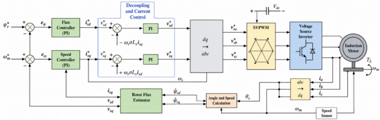



 Share This Article
 Twitter
 Linked In
 Facebook