Research Article | | Peer-Reviewed

Modulation of Wide Voltage Range Interface DC-DC Converter in DC Distribution System

Received: 7 May 2024    Accepted: 24 May 2024    Published: 4 July 2024
Views:       Downloads:
Abstract

Bipolar DC distribution systems rely on various power sources like photovoltaics and distributed energy storage, each with its unique voltage characteristics. To accommodate these fluctuations, interface converters must adjust over a wide voltage range. The bipolar non-isolated DC-DC converter emerges as a promising solution due to its versatile modulation capabilities, reduced switch voltage stress, and cost-effectiveness. This article explores how wide voltage range regulation is achieved in bipolar DC-DC converters interfacing with bipolar DC power grids. It delves into the operational strategies and modulation techniques employed, ensuring stable output despite varying input voltages. Design considerations and challenges associated with implementing such converters are also discussed. An experimental platform was constructed to validate the proposed methodology. Through rigorous testing and analysis, the effectiveness of the topology's operation mode was confirmed. Real-world data from the experimental setup provided insights into the converter's performance under different operating conditions, supporting its applicability for bipolar DC distribution systems. In summary, this article provides a comprehensive examination of wide voltage range regulation in bipolar DC-DC converters, highlighting their potential to enhance efficiency and reliability in bipolar DC power grids. Through theoretical discussions and practical validation, it contributes to the advancement and adoption of these converters in modern energy systems.

Published in American Journal of Electrical Power and Energy Systems (Volume 13, Issue 2)
DOI 10.11648/j.epes.20241302.11
Page(s) 21-31
Creative Commons

This is an Open Access article, distributed under the terms of the Creative Commons Attribution 4.0 International License (http://creativecommons.org/licenses/by/4.0/), which permits unrestricted use, distribution and reproduction in any medium or format, provided the original work is properly cited.

Copyright

Copyright © The Author(s), 2024. Published by Science Publishing Group

Keywords

Wide Voltage Range Input, Bipolar DC Grid, Multi Mode Switching, Bipolar DC-DC Converter

1. Introduction
In recent years, with the increasing adoption of new energy sources and advancements in power electronics technology, low-voltage Direct Current (DC) distribution systems, particularly those dominated by DC microgrids, have garnered widespread attention. Concurrently, the extensive application of distributed renewable energy sources and the rise in fluctuations of power electronic loads on the user side have intensified the power quality challenges faced by traditional Alternating Current (AC) distribution systems, particularly in current control, load distribution, and voltage regulation. Owing to their inherent design characteristics, conventional AC distribution systems are less efficient in addressing power quality issues and exhibit significant limitations when confronted with the growing number of distributed power sources and complex loads .
Given the increasing complexity of modern power systems, researchers and engineers are exploring more efficient and stable methods for power transmission and distribution. Unlike traditional systems, DC distribution systems are being widely adopted due to their efficient operation and superior power quality characteristics. These systems not only enhance power quality management and regulation but also improve overall system efficiency by simplifying control strategies . However, the widespread adoption of DC distribution systems imposes higher performance requirements on DC converter devices, which must maintain high efficiency and stability across a broad range of operating conditions.
DC-DC converters play a crucial role in DC power grids. These converters must not only exhibit high efficiency and low cost but also possess a wide range of voltage regulation capabilities to accommodate various application scenarios and operating conditions . For instance, conventional two-level boost converters, known for their simple structure and low cost, are extensively used in various low-voltage DC systems, meeting many basic application requirements.
For bipolar DC distribution systems, bipolar non-isolated DC-DC converters offer significant advantages. These converters can be directly connected to the bipolar DC bus without requiring a high-frequency isolation transformer, thereby simplifying system design and enhancing efficiency . This configuration not only reduces system complexity and cost but also minimizes electromagnetic interference issues associated with high-frequency transformers, thereby improving overall system reliability.
Bipolar DC-DC converters excel in high-voltage and high-power applications compared to conventional two-level DC-DC converters. Their primary advantages include reduced device voltage stress, increased system power rating, and decreased output filter size . These benefits make bipolar DC-DC converters highly competitive in high-power and high-voltage contexts. Specifically, reducing device voltage stress extends the lifespan of the device and enhances system reliability; increasing the system power rating addresses the demands of high-power devices; and minimizing the output filter size not only reduces the system's size and weight but also lowers costs and improves the system's dynamic response. Figure 1 illustrates the interconnection configuration of a bipolar DC-DC converter with a bipolar grid, along with its typical application scenarios. This converter design streamlines the system architecture while also opening up novel avenues for the integration of DC distribution systems into contemporary power grids. As technology advances persist, the bipolar DC-DC converter is poised to become an indispensable component of future power systems, catalyzing advancements in power transmission and distribution technology toward enhanced efficiency and reliability.
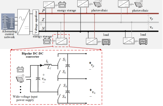
Figure 1. The topology and application scenarios of the DC-DC converter.
2. Bipolar DC-DC Converter Working Principle
The core principle underpinning the operation of the bipolar DC-DC converter to attain wide voltage regulation hinges upon its adaptive mode switching mechanism, designed to accommodate fluctuations in input voltage levels within predetermined parameters. This dynamic capability allows the converter to seamlessly transition between different operational modes, thereby facilitating access to diverse buses within the bipolar system and consequently enabling wide voltage regulation. Specifically, when confronted with low input voltage conditions, the converter seamlessly adjusts its operation to facilitate a two-level output mode, establishing connection with the unipolar bus of the bipolar system. Conversely, in instances where the input voltage exceeds predetermined thresholds, the converter seamlessly transitions to bipolar output mode, facilitating connection with the bipolar bus of the system. This strategic mode switching mechanism ensures optimal performance and efficacy of the converter across a broad spectrum of operating conditions, thereby facilitating robust wide voltage regulation capabilities within the bipolar DC distribution system.
2.1. Unipolar Access Mode
In unipolar mode, when the converter is connected to the positive terminal, switch tubes S1 and S2 alternate in an on-off pattern within one switching cycle, while S3 remains on and S4 remains off, as depicted in Figure 2.
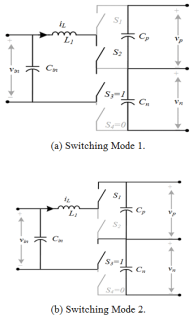
Figure 2. Switching mode of unipolar access mode.
Additionally, during switching mode 1, switching devices S2 and S3 are activated while S1 and S4 are deactivated. At this juncture, the input source voltage vin charges inductor L1. Conversely, in switching mode 2, switching devices S1 and S3 are engaged while S2 and S4 are disengaged. Consequently, the positive capacitor Cp on the input side is charged via switching tubes S1 and S3. Figure 3. illustrates the modulation mode of the converter during this phase. Given its application in bidirectional scenarios, the converter is assumed to operate in a continuous-on mode.
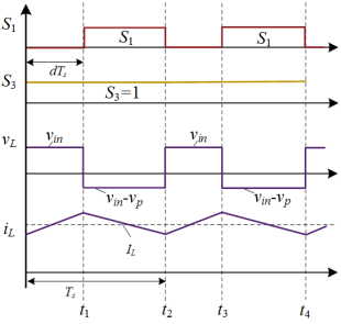
Figure 3. Modulation method of unipolar access mod.
According to the volt-second equilibrium principle, (1) can be obtained:
(1)
Where Ts refers to a switching period, t1 refers to the on-time of a switching tube S2 for a period, fsw refers to the switching frequency, and vp refers to the P pole bus voltage.
The switching duty cycle d in this paper is assumed to be:
(2)
The voltage gain of the converter in continuous conduction mode is given by:
(3)
The inductor current ripple at this time can be expressed as:
(4)
Similarly, when the converter is connected to the negative pole in unipolar mode, switch tubes S3 and S4 alternate during a switching cycle, with switch tube S1 being normally closed and switch tube S2 normally open. The switching pattern when the converter is connected to the negative pole is illustrated in Figure 4. During switching mode 1, switching devices S2 and S3 are activated while S1 and S4 are deactivated, causing the input source voltage vin to charge inductor L1. In switching mode 2, switching devices S2 and S4 conduct, while S1 and S3 are turned off, resulting in the input side charging the negative capacitor Cn through switching tubes S2 and S4. The modulation of the converter in this mode is depicted in Figure 5. Similarly, the voltage gain of the converter in continuous conduction mode can be obtained as M is still 1/(1-d), with the analysis process identical to that when accessing the positive terminal.
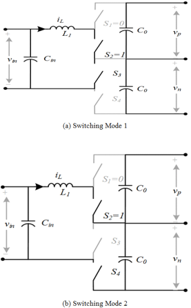
Figure 4. Switching mode of unipolar access mode.
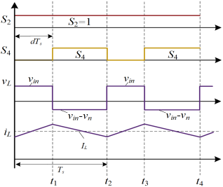
Figure 5. Modulation method of unipolar access mode.
2.2. Bipolar Access Mode
The bipolar DC-DC converter operates in bipolar access mode when the input voltage is high. The switching on/off modes during bipolar mode are illustrated in Figure 6. In Switching Mode 1 (M1), switching devices S1 and S4 are activated while S2 and S3 are deactivated. At this stage, the input voltage vin charges the output-side capacitors Cp and Cn through inductor L1 and switching tubes S1 and S4. In Switching Mode 2 (M2), switching devices S1 and S3 are conducting, whereas S2 and S4 are turned off, leading to vin charging the output side positive capacitor Cp through inductor L1 and switching tubes S1 and S3. Switching Mode 3 (M3) sees switching devices S2 and S4 activated while S1 and S3 are deactivated, resulting in vin being charged to the output side negative capacitor Cn through inductor L1 and switching tubes S2 and S4. Finally, in Switching Mode 4 (M4), switching devices S2 and S3 conduct, while S1 and S4 are turned off, causing vin to charge inductor L1 alone.
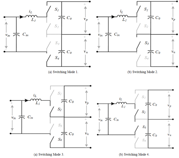
Figure 6. Switching mode of bipolar access mode.
The steady-state characteristics of the bipolar DC-DC converter are analyzed based on the above four switching modes. The converter in continuous conduction mode can be divided into two cases, d<0.5 and d>0.5, according to the magnitude of the duty cycle. Taking the phase of the carriers of switches S1 and S2 as a reference, the carriers of S3 and S4 are phase-shifted by 180° (half a cycle), and the corresponding modulated waveforms are shown in Figure 7.
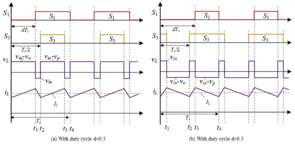
Figure 7. Modulation in bipolar access mode.
When d<0.5, the converter cycles between three switching modes within one cycle, following the sequence M1-M2-M1-M3. Conversely, when d>0.5, the sequence shifts to M2-M4-M3-M4 within one cycle. The voltage gain of the bipolar access mode can be derived as 1/(1-d) based on the volt-second balance of the inductance within one cycle.
In order to rationally design the value of inductor L1, the current ripple during converter operation is analyzed. Let the output side capacitor voltages are all vbus, the inductor current ripple can be expressed as a function of the duty cycle, expressed as follows.
(5)
According to the above equation, the maximum value of current ripple of the converter can be expressed as:
(6)
When the duty cycle d equals 0.25 or 0.75, the inductor current ripple reaches its maximum. Let ΔiLmax represent the maximum allowable ripple for the inductor design. In this case, the inductor value should satisfy the following equation:
(7)
Where: vmax is the maximum fluctuation value of DC bus voltage.
At identical switching frequencies, achieving the same current ripple necessitates an inductance for the bipolar DC-DC converter that is 25% of that required for two-level operation. In other words, the inductance for the bipolar converter is one-fourth the size of a conventional two-level DC-DC converter's inductance.
3. Control Strategy
This study outlines the control strategy of the bipolar DC-DC converter for wide voltage regulation, as illustrated in Figure 8, with specific reference to the energy storage battery on the input side. The output voltage of the energy storage battery exhibits a wide range of variation and is connected to a bipolar DC system through a bipolar DC-DC converter. The energy storage system generates a constant current output reference based on the state of charge of its internal battery.
Initially, the input side voltage vin of the converter, corresponding to the voltage across the energy storage, is detected. Subsequently, the converter operates in bipolar mode when the input side voltage vin is high, and in unipolar mode when it is low. The primary control objective of the converter is to maintain constant current output in both operating modes, despite fluctuations in the wide voltage of the energy storage battery.
The specific control methodology involves comparing the inductor current with the current reference value, followed by employing current loop proportional-integral (PI) control. Subsequently, the duty cycle d is generated through limitation, and ultimately, pulse width modulation (PWM) modulation is utilized to produce control signals for switching tube activation and deactivation.
Figure 8. Control strategy of the converter.
4. Simulation Validation
In order to ascertain the effectiveness of the bipolar DC-DC converter utilizing the wide voltage variable mode modulation approach, a rigorous validation process is undertaken. This involves the establishment of a sophisticated simulation model representing the bipolar DC distribution system, meticulously crafted within the Matlab/PLECS co-simulation environment. Through this comprehensive framework, we meticulously assess the performance of the converter through a series of circuit simulations. The intricate topology of the bipolar DC-DC converter, pivotal to this investigation, is visually elucidated in Figure 1, providing a clear understanding of its configuration and operational principles. Furthermore, to facilitate a thorough analysis, Table 1 is provided, detailing the simulation parameters employed within the circuit simulation model.
Table 1. Wide Voltage DC-DC Converter Simulation Parameter Table.

Circuit Parameter

Value

Switching frequencies fsw

50kHz

Filter inductor L1

950μH

Filter capacitor C1

120μF

Filter capacitor C2

120μF

Current loop kp

0.1, 0.08

Current loop ki

80, 60

Bipolar system bus voltage vbus

± 375V

Input voltage on storage side vin

200V~550V

Switching Tube S1~ S4 Model

C3M0045065D

Mode switching threshold vmode

320V

4.1. Verification of Wide Voltage Regulation Capability (Low Input Voltage)
In order to evaluate the effectiveness of the bipolar DC-DC converter functioning in unipolar mode, a systematic investigation is conducted whereby the energy storage system is interfaced with the bipolar DC system through the converter. This evaluation encompasses two distinctive operational scenarios: fluctuations in energy storage output current and variations in energy storage output voltage. The simulation results corresponding to the adjustment of energy storage output current are presented in Figure 9 (a). Initially, preceding the 0.1s mark, the current loop reference value is preset at 10A, maintaining the energy storage output voltage at 100V, with the inductor current precisely adhering to the specified current loop of 10A. Subsequently, at the 0.1s timestamp, the current loop reference value is modified to 15A, thereby inducing a seamless transition of the inductor current from 10A to 15A. Noteworthy is the observation that throughout this process, switching tube S1 pulses are activated periodically, whereas switching tube S4 consistently remains inactive, thus confirming the converter's adeptness at operating flawlessly in unipolar mode. Moreover, this experimental demonstration underscores the capability of the inductor current to seamlessly adjust to 15A within the unipolar mode, thereby corroborating the robust performance of the current loop mechanism.
The simulation results when the output voltage of the energy storage varies are shown in Figure 9 (b). Before 0.1 s, the input voltage of the converter (i. e., the output voltage of the energy storage) is 20V, and the output current is 10A. When 0.1s, to simulate that the output voltage of the energy storage varies in a wide range, the input voltage of the converter is increased from 20V to 180V, and in order to make the energy storage still output at a constant current, the reference value of the current loop is unchanged. According to the simulation results, it can be seen that the inductor current, after an overshoot in 0.1s, then drops to 10A, which is consistent with the average value of the energy storage output voltage before the change. The pulse of switch tube S1 turns on periodically during the whole process, the duty cycle increases at 0.1s, and the pulse of switch tube S4 is always off, which can verify that the converter works normally in the unipolar mode when the energy storage output voltage varies over a wide range.
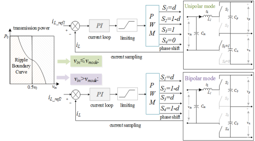
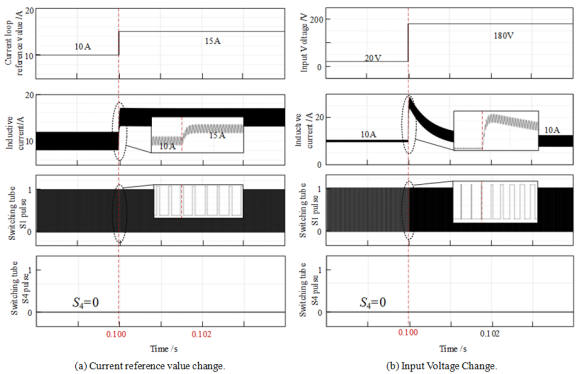
Figure 9. The converter operates in the unipolar state.
4.2. Verification of Wide Voltage Regulation Capability (High Input Voltage)
In order to verify the effectiveness of the converter in bipolar mode, the bipolar system is connected at a higher energy storage output voltage. Two working conditions are set up, which are energy storage output current change and energy storage output voltage change. The simulation results when the energy storage output current is changed are shown in Figure 10 (a). Before 0.1s, the reference value of the current loop is 15A, the output voltage of the energy storage is 250V, and the inductor current follows the current loop as 15A; when 0.1s, the reference value of the current loop is changed to 20A, and the inductor current responds to the change of the current loop from 15A to 20A. The pulses of the switching tubes S1 and S4 turn on periodically throughout the whole process, which can be verified that the converter can work normally and the current loop responds well in the bipolar mode. It can be verified that the converter can work normally in bipolar mode and the current loop response is good.
The simulation results when the output voltage of the energy storage varies are shown in Figure 10 (b). The input voltage of the converter (i. e., the output voltage of the energy storage) is 200V and the output current is 25A. When 0.1s, to simulate that the output voltage of the energy storage varies in a wide range, the input voltage of the converter is increased from 200V to 300V. To make the energy storage still output at constant current, the reference value of the current loop is unchanged. According to the simulation results, it can be seen that the inductor current appears in 0.1s after the overshoot, and then drops to 25A, which is consistent with the average value of the energy storage output voltage before the change. The pulses of switch tubes S1 and S4 are turned on periodically throughout the process, and the duty cycle is changed at 0.1s, which verifies that the converter can still work normally when the energy storage output voltage varies over a wide range in the bipolar mode.
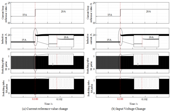
Figure 10. The converter operates in the bipolar state.
5. Experimental Verification
In order to verify the validity and advantages of the operating mode of the wide voltage DC-DC converter, a wide voltage regulated converter prototype was constructed based on the Myway controller experimental platform. The topology of the bipolar DC-DC converter is depicted in Figure 1. The specifications of the components include a filter inductor of 200μH, positive and negative output-side capacitances of 660μF each, and a switching frequency of 50kHz. Additionally, the current-loop proportionality coefficient is set at 0.012, the current-loop integral coefficient at 0.005, and the bus voltage of the bipolar system is maintained at 96V (±48V). Furthermore, the converter mode switching threshold is configured to be 40V.
Then, the energy storage is connected to a bipolar DC system through a bipolar DC-DC converter. The setup condition is the energy storage output voltage change. The experimental results when the energy storage output voltage is changed are shown in Figure 11.
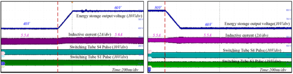
Figure 11. Changes in input voltage of bipolar mode energy storage.
In Figure 11 (a), the output voltage of the energy storage rises from 40V to 60V, the reference value of the current loop is always 5.5A, and the current rises to 5.6A. In Figure 11 (b), the output voltage of the energy storage decreases from 80V to 60V, the reference value of the current loop is always 5.5A, and the current is still about 5.5A. The output voltage of the energy storage decreases from 80V to 60V, the reference value of the current loop is always 5.5A, and the current remains about 5.5A.
6. Conclusions
This study introduces a novel approach to tackle voltage variations stemming from the system source, presenting a scheme aimed at achieving wide voltage regulation for distributed power supplies. The proposed methodology involves linking these supplies to a bipolar system via a bipolar DC-DC converter. Capitalizing on the broad voltage regulation and multi-mode operation capabilities inherent in this converter, the seamless integration of the distributed power supply with the bipolar system is realized. Irrespective of the operational mode—whether unipolar or bipolar—the converter consistently maintains a constant-current output, even in the face of significant voltage fluctuations at the input. Furthermore, in instances where the output voltage of the distributed power supply decreases, the bipolar converter smoothly transitions to a two-level output mode by adapting its modulation scheme, thereby ensuring adaptable and effective operation. Ultimately, the efficacy of wide voltage regulation is substantiated through experimentation conducted with a small-scale power prototype, validating the proposed approach's practical viability and robustness in real-world scenarios.
Abbreviations

DC

Direct Current

AC

Alternating Current

Conflicts of Interest
The authors declare that there are no conflicts of interest regarding the publication of this paper.
References
[1] J. -C. Kim, S. -M. Cho and H. -S. Shin, "Advanced Power Distribution System Configuration for Smart Grid," in IEEE Transactions on Smart Grid, vol. 4, no. 1, pp. 353-358, March 2013,
[2] M. Saeedifard, M. Graovac, R. F. Dias and R. Iravani, "DC power systems: Challenges and opportunities," IEEE PES General Meeting, Minneapolis, MN, USA, 2010, pp. 1-7,
[3] V. A. K. Prabhala, B. P. Baddipadiga and M. Ferdowsi, "DC distribution systems — An overview," 2014 International Conference on Renewable Energy Research and Application (ICRERA), Milwaukee, WI, USA, 2014, pp. 307-312,
[4] F. S. Al-Ismail, "DC Microgrid Planning, Operation, and Control: A Comprehensive Review," in IEEE Access, vol. 9, pp. 36154-36172, 2021,
[5] J. Brenguier, M. Vallet and F. VAILLANT, "Efficiency gap between AC and DC electrical power distribution system," 2016 IEEE/IAS 52nd Industrial and Commercial Power Systems Technical Conference (I&CPS), Detroit, MI, USA, 2016, pp. 1-6,
[6] M. Starke, L. M. Tolbert and B. Ozpineci, "AC vs. DC distribution: A loss comparison," 2008 IEEE/PES Transmission and Distribution Conference and Exposition, Chicago, IL, USA, 2008, pp. 1-7,
[7] M. E. Baran and N. R. Mahajan, "DC distribution for industrial systems: opportunities and challenges," in IEEE Transactions on Industry Applications, vol. 39, no. 6, pp. 1596-1601, Nov.-Dec. 2003,
[8] H. Kakigano, Y. Miura and T. Ise, "Low-Voltage Bipolar-Type DC Microgrid for Super High Quality Distribution," in IEEE Transactions on Power Electronics, vol. 25, no. 12, pp. 3066-3075, Dec. 2010,
[9] J. Ma, M. Zhu, Y. Li and X. Cai, "Monopolar Fault Reconfiguration of Bipolar Half Bridge Converter for Reliable Load Supply in DC Distribution System," in IEEE Transactions on Power Electronics, vol. 37, no. 9, pp. 11305-11318, Sept. 2022,
[10] L. Tan, B. Wu, S. Rivera and V. Yaramasu, "Comprehensive DC Power Balance Management in High-Power Three-Level DC–DC Converter for Electric Vehicle Fast Charging," in IEEE Transactions on Power Electronics, vol. 31, no. 1, pp. 89-100, Jan. 2016,
[11] L. Tan, B. Wu, V. Yaramasu, S. Rivera and X. Guo, "Effective Voltage Balance Control for Bipolar-DC-Bus-Fed EV Charging Station With Three-Level DC–DC Fast Charger," in IEEE Transactions on Industrial Electronics, vol. 63, no. 7, pp. 4031-4041, July 2016,
[12] S. Rivera, R. Lizana F., S. Kouro, T. Dragičević and B. Wu, "Bipolar DC Power Conversion: State-of-the-Art and Emerging Technologies," in IEEE Journal of Emerging and Selected Topics in Power Electronics, vol. 9, no. 2, pp. 1192-1204, April 2021,
[13] H. Zhu, M. Zhu, J. Zhang, X. Cai and N. Dai, "Topology and operation mechanism of monopolarto-bipolar DC-DC converter interface for DC grid," 2016 IEEE 8th International Power Electronics and Motion Control Conference (IPEMC-ECCE Asia), Hefei, China, 2016, pp. 3728-3733,
[14] G. V. d. Broeck, W. Martinez, M. Dalla Vecchia, S. Ravyts and J. Driesen, "Conversion Efficiency of the Buck Three-Level DC–DC Converter in Unbalanced Bipolar DC Microgrids," in IEEE Transactions on Power Electronics, vol. 35, no. 9, pp. 9306-9319, Sept. 2020,
[15] X. Zhang, C. Gong and Z. Yao, "Three-Level DC Converter for Balancing DC 800-V Voltage," in IEEE Transactions on Power Electronics, vol. 30, no. 7, pp. 3499-3507, July 2015,
[16] X. Yu, K. Jin and Z. Liu, "Capacitor Voltage Control Strategy for Half-Bridge Three-Level DC/DC Converter," in IEEE Transactions on Power Electronics, vol. 29, no. 4, pp. 1557-1561, April 2014,
[17] A. Ganjavi, H. Ghoreishy and A. A. Ahmad, "A Novel Single-Input Dual-Output Three-Level DC–DC Converter," in IEEE Transactions on Industrial Electronics, vol. 65, no. 10, pp. 8101-8111, Oct. 2018,
[18] G. Van den Broeck, S. De Breucker, J. Beerten, J. Zwysen, M. Dalla Vecchia and J. Driesen, "Analysis of three-level converters with voltage balancing capability in bipolar DC distribution networks," 2017 IEEE Second International Conference on DC Microgrids (ICDCM), Nuremburg, Germany, 2017, pp. 248-255,
[19] J. Lago, J. Moia and M. L. Heldwein, "Evaluation of power converters to implement bipolar DC active distribution networks — DC-DC converters," 2011 IEEE Energy Conversion Congress and Exposition, Phoenix, AZ, USA, 2011, pp. 985-990,
[20] V. Monteiro, T. J. C. Sousa, D. Pedrosa, S. Coelho and J. L. Afonso, "A Three-Level dc-dc Converter for Bipolar dc Power Grids: Analysis and Experimental Validation," IECON 2020 The 46th Annual Conference of the IEEE Industrial Electronics Society, Singapore, 2020, pp. 3761-3766,
[21] J. Ma, M. Zhu, X. Cai and Y. W. Li, "DC Substation for DC Grid—Part II: Hierarchical Control Strategy and Verifications," in IEEE Transactions on Power Electronics, vol. 34, no. 9, pp. 8682-8696, Sept. 2019,
[22] X. Li and S. Wang, "Energy management and operational control methods for grid battery energy storage systems," in CSEE Journal of Power and Energy Systems, vol. 7, no. 5, pp. 1026-1040, Sept. 2021,
[23] Chendan Li, T. Dragicevic, N. L. Diaz, J. C. Vasquez and J. M. Guerrero, "Voltage scheduling droop control for State-of-Charge balance of distributed energy storage in DC microgrids," 2014 IEEE International Energy Conference (ENERGYCON), Cavtat, Croatia, 2014, pp. 1310-1314,
[24] D. Razmi, T. Lu, B. Papari, E. Akbari, G. Fathi and M. Ghadamyari, "An Overview on Power Quality Issues and Control Strategies for Distribution Networks With the Presence of Distributed Generation Resources," in IEEE Access, vol. 11, pp. 10308-10325, 2023,
[25] J. Ma, M. Zhu, Y. Li and X. Cai, "Dynamic Analysis of Multimode Buck–Boost Converter: An LPV System Model Point of View," in IEEE Transactions on Power Electronics, vol. 36, no. 7, pp. 8539-8551, July 2021,
Cite This Article
  • APA Style

    Zhang, D., Ouyang, Z., Ma, W., Shen, X., Lv, J., et al. (2024). Modulation of Wide Voltage Range Interface DC-DC Converter in DC Distribution System. American Journal of Electrical Power and Energy Systems, 13(2), 21-31. https://doi.org/10.11648/j.epes.20241302.11

    Copy | Download

    ACS Style

    Zhang, D.; Ouyang, Z.; Ma, W.; Shen, X.; Lv, J., et al. Modulation of Wide Voltage Range Interface DC-DC Converter in DC Distribution System. Am. J. Electr. Power Energy Syst. 2024, 13(2), 21-31. doi: 10.11648/j.epes.20241302.11

    Copy | Download

    AMA Style

    Zhang D, Ouyang Z, Ma W, Shen X, Lv J, et al. Modulation of Wide Voltage Range Interface DC-DC Converter in DC Distribution System. Am J Electr Power Energy Syst. 2024;13(2):21-31. doi: 10.11648/j.epes.20241302.11

    Copy | Download

  • @article{10.11648/j.epes.20241302.11,
      author = {Dezhen Zhang and Zhen Ouyang and Wei Ma and Xiang Shen and Jinwei Lv and Yangxin Zou},
      title = {Modulation of Wide Voltage Range Interface DC-DC Converter in DC Distribution System
    },
      journal = {American Journal of Electrical Power and Energy Systems},
      volume = {13},
      number = {2},
      pages = {21-31},
      doi = {10.11648/j.epes.20241302.11},
      url = {https://doi.org/10.11648/j.epes.20241302.11},
      eprint = {https://article.sciencepublishinggroup.com/pdf/10.11648.j.epes.20241302.11},
      abstract = {Bipolar DC distribution systems rely on various power sources like photovoltaics and distributed energy storage, each with its unique voltage characteristics. To accommodate these fluctuations, interface converters must adjust over a wide voltage range. The bipolar non-isolated DC-DC converter emerges as a promising solution due to its versatile modulation capabilities, reduced switch voltage stress, and cost-effectiveness. This article explores how wide voltage range regulation is achieved in bipolar DC-DC converters interfacing with bipolar DC power grids. It delves into the operational strategies and modulation techniques employed, ensuring stable output despite varying input voltages. Design considerations and challenges associated with implementing such converters are also discussed. An experimental platform was constructed to validate the proposed methodology. Through rigorous testing and analysis, the effectiveness of the topology's operation mode was confirmed. Real-world data from the experimental setup provided insights into the converter's performance under different operating conditions, supporting its applicability for bipolar DC distribution systems. In summary, this article provides a comprehensive examination of wide voltage range regulation in bipolar DC-DC converters, highlighting their potential to enhance efficiency and reliability in bipolar DC power grids. Through theoretical discussions and practical validation, it contributes to the advancement and adoption of these converters in modern energy systems.
    },
     year = {2024}
    }
    

    Copy | Download

  • TY  - JOUR
    T1  - Modulation of Wide Voltage Range Interface DC-DC Converter in DC Distribution System
    
    AU  - Dezhen Zhang
    AU  - Zhen Ouyang
    AU  - Wei Ma
    AU  - Xiang Shen
    AU  - Jinwei Lv
    AU  - Yangxin Zou
    Y1  - 2024/07/04
    PY  - 2024
    N1  - https://doi.org/10.11648/j.epes.20241302.11
    DO  - 10.11648/j.epes.20241302.11
    T2  - American Journal of Electrical Power and Energy Systems
    JF  - American Journal of Electrical Power and Energy Systems
    JO  - American Journal of Electrical Power and Energy Systems
    SP  - 21
    EP  - 31
    PB  - Science Publishing Group
    SN  - 2326-9200
    UR  - https://doi.org/10.11648/j.epes.20241302.11
    AB  - Bipolar DC distribution systems rely on various power sources like photovoltaics and distributed energy storage, each with its unique voltage characteristics. To accommodate these fluctuations, interface converters must adjust over a wide voltage range. The bipolar non-isolated DC-DC converter emerges as a promising solution due to its versatile modulation capabilities, reduced switch voltage stress, and cost-effectiveness. This article explores how wide voltage range regulation is achieved in bipolar DC-DC converters interfacing with bipolar DC power grids. It delves into the operational strategies and modulation techniques employed, ensuring stable output despite varying input voltages. Design considerations and challenges associated with implementing such converters are also discussed. An experimental platform was constructed to validate the proposed methodology. Through rigorous testing and analysis, the effectiveness of the topology's operation mode was confirmed. Real-world data from the experimental setup provided insights into the converter's performance under different operating conditions, supporting its applicability for bipolar DC distribution systems. In summary, this article provides a comprehensive examination of wide voltage range regulation in bipolar DC-DC converters, highlighting their potential to enhance efficiency and reliability in bipolar DC power grids. Through theoretical discussions and practical validation, it contributes to the advancement and adoption of these converters in modern energy systems.
    
    VL  - 13
    IS  - 2
    ER  - 

    Copy | Download

Author Information