Abstract
This study conducted slope and seepage stability analysis of a rock fill dam by comparing the clay core geometry. The core geometry in this study has been changed from a vertical to an inclined arrangement, and all analyses have been conducted are compared with the original design. The geometry of the inclined clay core dam was fixed and checked for static loading conditions. The analysis has been conducted using numerical modeling software called GEO-Studio 2012. Based on calculations, the flux through the dam with an inclined clay core is 0.0057 m3/sec, while the flux from the original dam with a vertical core is 0.0073 m3/sec. The safety factors for the downstream slope during steady state, sudden drawdown, end of construction, and the construction stage are 1.72, 1.56, 1.53, 1.64, and 1.59, respectively. These values were obtained from the original dam design with a vertical clay core, and the corresponding safety factors are 1.63, 1.54, 1.63, and 1.57, respectively. Therefore, the geometry of the clay core is considered safe based on the allowable limit factor of safety and seepage. In addition to this, the inclined clay core section was found to be significantly more Economical compared to the vertical clay core.
Keywords
Embankment, Stability Analysis, Awash Dam, Material Properties, Clays, Cores
1. Introduction
Embankment dams, which are constructed using earth and rock fill material, are commonly referred to as embankment dams or filled dams. About 63 countries in the world are currently associated with dams that have a height greater than 15m, which are referred to as high dams (Njiru and Siriba 2018). Among these, more than 70% are embankment dams. Building such dams is extremely significant for evolving countries like Ethiopia, which have not fully utilized their water resources to the required level. Nowadays, numerous embankment dams are in the design and construction phases across the country. However, the industry faces many challenges in terms of design and construction perspectives, because of the nature of the varying foundation condition and the range of properties of the material available for construction
| [2] | Baye, Melese. 2020. “Construction Quality Control of the Dam, a Case of Kesem Dam (Ethiopia),” no. June. |
[2]
and
| [16] | Mulat, Asegdew G., and Semu A. Moges. 2014. “Assessment of the Impact of the Grand Ethiopian Renaissance Dam on the Performance of the High Aswan Dam.” Journal of Water Resource and Protection 6(6): 583-98.
https://doi.org/10.4236/jwarp.2014.66057 |
[16]
.
The selection of the most suitable type of dam for a specific site requires careful evaluation of the characteristics of each type, taking into account the physical features of the site and its intended purposes, as well as safety, cost-effectiveness, and other relevant constraints. The final decision on the type of dam should be made after considering all these factors
| [4] | Biswas, Asit K. 1968. “Discussion of ‘Influences on Selection of the Type of Dam.’” Journal of the Soil Mechanics and Foundations Division 94(2): 576-78.
https://doi.org/10.1061/jsfeaq.0001114 |
[4]
and
.
The choice between natural and artificial sealing is made mainly in respect of the availability of material and the cost of its processing, hauling, dumping and compacting. All dams designed and according to current standards will have acceptable factors of safety
| [19] | Rashidi, Mohammad, and S Mohsen Haeri. 2017. “Journal of Rock Mechanics and Geotechnical Engineering Evaluation of Behaviors of Earth and Rock Fi Ll Dams during Construction and Initial Impounding Using Instrumentation Data and Numerical Modeling.” Journal of Rock Mechanics and Geotechnical Engineering 9(4): 709-25.
https://doi.org/10.1016/j.jrmge.2016.12.003 |
[19]
. The task is to find the most appropriate type, considering all technical and economic aspects and taking into account the actual details of the site
| [13] | Kutzner, Christian. 2018. “Earth and Rockfill Dams: Principles for Design and Construction.” Earth and Rockfill Dams: Principles for Design and Construction.
https://doi.org/10.1201/9780203758991 |
[13]
.
The availability of critical construction materials such as cement, aggregate, sand, and filter drainages also play a significant role in determining the type of dam to be selected
. Topography is also a significant factor in the selection of a dam. Narrow gorges with U and V shapes are favorable for gravity or arch dams, while wide and flat terrains are best for embankment dams
| [20] | Sandra, Dra, Elizondo Argueta, Niels H Wacher, Mara Silva, Leticia Valdez, Miguel Cruz, Rita A Gómez-Díaz, et al. 2016. “No Analysis of the co-dispersion structure of health-related indicators, the center of the subject's sense of health, and the elderly people living at home. Title.” Revista CENIC. Ciencias Biológicas 152 (3): 28. |
[20]
and
| [6] | Duncan, J. M., Stephen G Wright, and Brandon Thomas L. 2014. “Soil Strength and Slope Stability.” John Wiley & Sons 2(1): 37-72. |
[6]
.
Embankment dams with a vertical clay core have an advantage. The core has a relatively small effect on embankment slope stability because it is located deep inside the embankment. Additionally, the possibility of contact seepage between the core and the foundation is reduced due to the high contact pressure at this location
| [17] | Nayebzadeh, R., and M. Mohammadi. 2011. “The Effect of Impervious Clay Core Shape on the Stability of Embankment Dams.” Geotechnical and Geological Engineering 29(4): 627-35. https://doi.org/10.1007/s10706-011-9395-z |
[17]
. El-Infefiernillo (Mexico, 148m high), is among the tallest dams with vertical clay core arrangements
| [3] | Berhe, Tensay G. 2010. “Effect of Canyon Geometry and Ground Conditions on the Seismic Performance of Tendaho Earthfill Dam in Ethiopia.,” no. 4: 1-12. |
[3]
and
| [22] | Tadesse, Abebe Arega, and Bikila Teklu. 1999. “School of Graduate Studies Construction Quality Monitoring of Embankment Dams Using Pore Water Pressure, the Case of Kesem Dam Approved By Board of Examiners.” |
[22]
. In Ethiopia, this type of core arrangement is common and widely used. Most dams in Ethiopia with natural sealing follow this design. Those dams are. Tendaho, Gidabo, Ribb, Megech, Kesem, Welkite, Gilgel Abay, Jema, and Wolkayt Rock Fill Dam
| [8] | Gemeda, Desta. 2020. “The Alternative Design of Gidabo Embankment Dam by Introducing Asphalt Concrete Core: Southern Ethiopia.” International Journal of Scientific & Engineering Research 11(3): 1158-75. http://www.ijser.org |
[8]
and
| [16] | Mulat, Asegdew G., and Semu A. Moges. 2014. “Assessment of the Impact of the Grand Ethiopian Renaissance Dam on the Performance of the High Aswan Dam.” Journal of Water Resource and Protection 6(6): 583-98.
https://doi.org/10.4236/jwarp.2014.66057 |
[16]
.
The impervious clay zone of an embankment dam has lower shear strength than the shell zone. Therefore, the location, width, and inclination of this zone has a significant effect on the stability, seepage control, and deformation characteristics of the embankment
. Clay core zones in embankment dams may have either vertical or inclined geometry depending on the site conditions
| [14] | Li, Changwen, Huabin Gao, Zhaoming Xu, and Yan Huang. 2021. “Sensitivity Analysis of Rock-Fill Dam Break Flood on Different Dam Break Durations.” Open Journal of Safety Science and Technology 11(3): 89-103.
https://doi.org/10.4236/ojsst.2021.113007 |
[14]
and
| [8] | Gemeda, Desta. 2020. “The Alternative Design of Gidabo Embankment Dam by Introducing Asphalt Concrete Core: Southern Ethiopia.” International Journal of Scientific & Engineering Research 11(3): 1158-75. http://www.ijser.org |
[8]
. The vertical core is arranged in a more or less symmetrical manner along the dam axis. These types of core arrangements in the design and construction of embankment dams are common, and many dams with such core arrangements have been constructed worldwide
| [1] | Assefa, Eleyas, Li Jian Lin, Costas I. Sachpazis, Deng Hua Feng, Sun Xu Shu, and Anthimos S. Anastasiadis. 2016. “Probabilistic Slope Stability Evaluation for the New Railway Embankment in Ethiopia.” Electronic Journal of Geotechnical Engineering 21(11): 4247-72. |
[1]
.
Depending on the specific advantages of the site, the core geometry might be designed to be sloping. The inclined core arrangement has several advantages over the vertical core in terms of shear stress concentration, plastic yield point, and resistance against hydraulic fracturing during sudden reservoir fill-up
| [17] | Nayebzadeh, R., and M. Mohammadi. 2011. “The Effect of Impervious Clay Core Shape on the Stability of Embankment Dams.” Geotechnical and Geological Engineering 29(4): 627-35. https://doi.org/10.1007/s10706-011-9395-z |
[17]
and
| [20] | Sandra, Dra, Elizondo Argueta, Niels H Wacher, Mara Silva, Leticia Valdez, Miguel Cruz, Rita A Gómez-Díaz, et al. 2016. “No Analysis of the co-dispersion structure of health-related indicators, the center of the subject's sense of health, and the elderly people living at home. Title.” Revista CENIC. Ciencias Biológicas 152 (3): 28. |
[20]
. Embankment dams with an inclined clay core geometry are common and widely used in other countries. Dams with this geometric arrangement have the advantage of a higher factor of safety for upstream slope failure, estimated at approximately 50%. Most inclined clay core dams can be constructed as heterogeneous structures, and foundation grouting can be conducted concurrently with the construction of the downstream shell. This design also provides improved performance and resistance to earthquake loading
| [12] | Khanna, Rajesh, Manoj Datta, and G. V. Ramana. 2014. “Influence of Inclination of Thin Core on Stability of Upstream Slope of Earth and Rockfill Dams.” Electronic Journal of Geotechnical Engineering 19 U: 6293-6305. |
[12]
.
Some studies
| [12] | Khanna, Rajesh, Manoj Datta, and G. V. Ramana. 2014. “Influence of Inclination of Thin Core on Stability of Upstream Slope of Earth and Rockfill Dams.” Electronic Journal of Geotechnical Engineering 19 U: 6293-6305. |
[12]
and
| [17] | Nayebzadeh, R., and M. Mohammadi. 2011. “The Effect of Impervious Clay Core Shape on the Stability of Embankment Dams.” Geotechnical and Geological Engineering 29(4): 627-35. https://doi.org/10.1007/s10706-011-9395-z |
[17]
concluded that embankment dams with inclined cores are preferable for seismic load conditions when the dam foundation has a steep slope (0.75H: 1V) along the river, there is a relatively impervious and strong foundation upstream of the dam axis, and the dam is being constructed in a highly seismic zone. They further stated that different construction processes are required for the placement of inclined core and shell materials. Orville Dam, which is 235 meters high in the USA, and Salto Santiago dam, which is 80 meters high in Brazil, are two of the largest earth-rock fill embankment dams with an inclined core arrangement
and
| [11] | Hasani, H., J. Mamizadeh, and H. Karimi. 2013. “Stability of Slope and Seepage Analysis in Earth Fills Dams Using Numerical Models (Case Study: Ilam DAM-Iran).” World Applied Sciences Journal 21(9): 1398-1402.
https://doi.org/10.5829/idosi.wasj.2013.21.9.1313 |
[11]
.
With the exception of the coffer dam of the Tendaho dam project (Ethiopia Construction Design and Supervision Work Corporation 2007-2016), no major embankment dam with a similar core geometry has been constructed in Ethiopia. Many researchers have studied various issues associated with inclined core geometry and have introduced specific characteristics and their advantages.
| [15] | López-Querol, S., and P. J. M. Moreta. 2008. “Performance of Heterogeneous Earthfill Dams under Earthquakes: Optimal Location of the Impervious Core.” Natural Hazards and Earth System Science 8(1): 9-18.
https://doi.org/10.5194/nhess-8-9-2008 |
[15]
and
, and have numerically investigated the performance of clay core arrangements in earthen dams. A typical cross section of an embankment dam was used for investigation and four different core arrangements were analyzed: a vertical clay core, a 200 inclined core facing upstream, a 400 inclined core facing upstream, and a clay blanket on the upstream slope face.
The study
| [17] | Nayebzadeh, R., and M. Mohammadi. 2011. “The Effect of Impervious Clay Core Shape on the Stability of Embankment Dams.” Geotechnical and Geological Engineering 29(4): 627-35. https://doi.org/10.1007/s10706-011-9395-z |
[17]
have also studied the effect of clay core shape on the stability of an embankment dam. These researchers conducted their study on the Ghavoshan rock fill dam, located in western Iran. The study considered the design of three different cores: a vertical clay core; a moderately sloping clay core (2.5H: 1V); and a steeply sloping clay core (0.75H: 1V). A numerical model of SIGMA/W has been used for the analysis. Deformation, stress distribution, and resistance to hydraulic fracturing have been considered as comparative parameters. Based on the investigation, the researchers found that the dam with a steeply sloping core (0.75H: 1V) has perform better in terms of embankment deformation and resistance to hydraulic fracturing.
The finite element method has been applied by
| [5] | Chen, Bo, Li Zhang, Qiupei Qian, Yanhong Dou, and Zhuohao Ji. 2017. “Research on the Seepage Safety Monitoring Indexes of the High Core Rockfill Dam.” World Journal of Engineering and Technology 5(3): 42-53.
https://doi.org/10.4236/wjet.2017.53b006 |
[5]
and
| [15] | López-Querol, S., and P. J. M. Moreta. 2008. “Performance of Heterogeneous Earthfill Dams under Earthquakes: Optimal Location of the Impervious Core.” Natural Hazards and Earth System Science 8(1): 9-18.
https://doi.org/10.5194/nhess-8-9-2008 |
[15]
to analyze the Hongxing earth dam in Taiwan, which has an inclined clay core. Stress distribution and dam deformation were the major parameters studied in this research, and it was found that inclined core embankments have better performance in terms of deformation than vertical clay core embankments. After studying the economic benefits of an inclined clay core in the earth dam of Hongxing dam, it has been concluded that this structure is both economical and safe. It is reliable and meets all the design requirements.
López-Querol, S. et al.
| [15] | López-Querol, S., and P. J. M. Moreta. 2008. “Performance of Heterogeneous Earthfill Dams under Earthquakes: Optimal Location of the Impervious Core.” Natural Hazards and Earth System Science 8(1): 9-18.
https://doi.org/10.5194/nhess-8-9-2008 |
[15]
studied the performance of heterogeneous earth-fill dams under earthquakes and the optimal location of the impervious core. An investigation was conducted on a typical heterogeneous fill dam, and a finite element numerical code was used for analysis. Liquefaction potential, soil degradation, and crest settlement were the main parameters investigated. Based on the study, it was found that the dam with a higher core slope had better performance. The researcher recommended that the location of the core material should be considered as a design criterion.
Therefore, the idea of investigating the Middle Awash dam by modifying the geometry of the impervious zone is supported by all the aforementioned studies on the geometry and arrangement of clay cores. Additionally, no significant dam with this type of core arrangement has yet been planned or constructed in Ethiopia, so designers should consider this when designing the dam.
According to the detailed design report for the Middle Awash multipurpose dam (ECDSWC, 2016), the dam core is planned to be constructed on fault breccia, which is unsuitable as a core foundation unless extensive foundation treatment, such as jet grouting, is performed. Furthermore, the borrow area designated for the impervious zone is located more than 15 km from the dam site, making the hauling distance considerably costly compared to other fill material locations. Consequently, the project is expected to incur significant additional expenses due to the need for extensive foundation treatment of the fault breccia with jet grouting and the absence of suitable clay material within a reasonable hauling distance.
2. Materials and Method
2.1. Details of Middle Awash Dam
The Middle Awash Dam is located between the Oromia and Afar National Regional States. The dam site is 15 kilometers from the borrow area designated for the core material. The proposed dam site can be accessed via the main asphalt road that runs from Addis Ababa to Djibouti (ECDSWC, 2016). According to the Middle Awash multipurpose dam's detailed design report (ECDSWC, 2016), the dam core is planned to be positioned on fault breccia.
However, it is not acceptable to use fault breccia as a core foundation unless extensive foundation treatment, such as jet grouting, has been performed. Since transporting large quantities of clay core material from the borrow area—located more than 15 km from the dam site—is not cost-effective, jet grouting of the fault breccia foundation is necessary, which increases project costs.
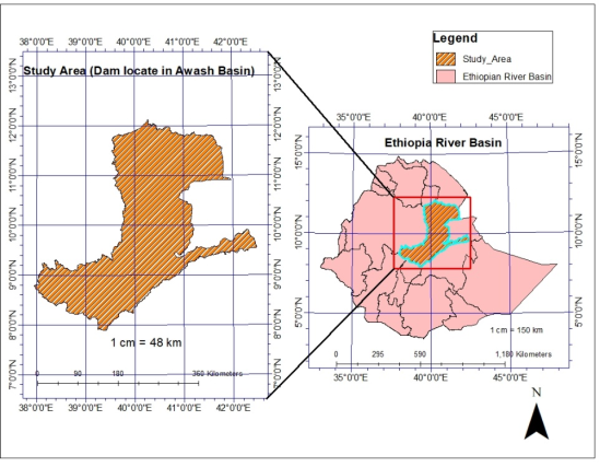
2.2. Location of the Study Area
The project of the study is located in Awash River Basin with geographic coordinates of Universal Transverse Mercator (UTM) of 990798m Northing and 629786m Easting at the center of the dam site. The location of the project area is shown in
Figure 1.
Figure 1. Location Map of the Study Area or project.
2.3. Data Collection
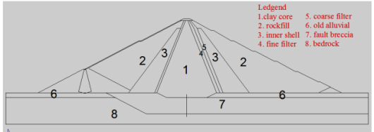
The maximum dam cross-section of the original design (central vertical clay core) prepared by water works design and supervision enterprise (ECSDWC, 2016) (
Figure 2) are shown below.
The maximum dam cross-section of the original design (central vertical clay core) prepared by water works design and supervision enterprise (ECDSWC, 2016) (
Figure 2) are shown below.
Figure 2. Middle Awash Dam Vertical Clay Core Geometry.
The other data was collected from Ethiopia construction design and supervision works corporation organization (ECDSWC, 2016) and Geo Studio software manual document. The collected data was presented as
Table 1.
2.3.1. Parameters Used for Seepage Analysis
Table 1. Permeability coefficients used in the analysis (ECDSWC, 2016).
0 | Permeability (m/sec) | Remark |
Fine filter | 4.76 x 10⁻⁸ | Design Report ECDSWC 2016 |
Coarse filter | 7.9 x 10⁻⁵ | Design Report ECDSWC 2016 |
Inner shell | 0.05 | Design Report ECDSWC 2016 |
Rock fill | 0.05 | Design Report ECDSWC 2016 |
Old Alluvial | 1.0 x 10⁻⁵ | Design Report ECDSWC 2016 |
Fault Breccia | 1.33 x 10⁻⁵ | Design Report ECDSWC 2016 |
Foundation Bed Rock | 1.0 x 10⁻⁹ | Design Report ECDSWC 2016 |
Table 2.
Volumetric water content of embankment material | [21] | SEEP/W. 2012. “Seepage Modeling with SEEP / W.” GEO-SLOPE International Ltd., no. July: 1-199.
http://www.geo-slope.com |
Material | SVWC | Remark |
Clay Core | 0.5 | SEEP/W sample function |
Fine filter | 0.35 | SEEP/W sample function |
Coarse filter | 0.28 | SEEP/W sample function |
Inner shell | 0.27 | SEEP/W sample function |
Rock fill | 0.25 | SEEP/W sample function |
2.3.2. Parameters Used for Slope Stability Analysis
Table 3. Shear strength parameter used for analysis (ECSDWC, 2016).
Material | Unit Weight (KN/m3) | C, (kpa) | φ,, (degree) | Remark |
Clay core | 16 | 20 | 23 | Design Report |
Fine filter | 20 | 0 | 32 | Design Report |
Coarse Filter | 20 | 0 | 34 | Design Report |
Inner shell | 20 | 0 | 34 | Design Report |
Rock fill | 22 | 0 | 42 | Design Report |
Old Alluvial | 20 | 5 | 34 | Design Report |
Fault Breccia | 17 | 10 | 34 | Design Report |
Foundation bed rock | Bed Rock | Bed Rock | Bed rock | Design Report |
Table 4. Pore water pressure ratio (ru) values for construction condition [9].
Material | Pore- water pressure ratio (ru) at during construction | Pore- water pressure ratio (ru) at After construction |
Clay core | 0.45 | 0.4 |
0ld Alluvial | 0.35 | 0.3 |
Fault Breccia | 0.35 | 0.3 |
2.4. Materials and Methods
For this study, Geo-Studio 2012 package was used for analysis and from the tools of software, the first two: SEEP/W, and SLOPE/W was used depending up on the problem to be examined. The intent of this study is to prepare an inclined clay core and compare with vertical clay core. Thus, the study was included: -
2.4.1. Dam Dimensioning
An intensive literature review on embankment dam design was carried out to determine appropriate dimensions and zoning of an alternative design.
2.4.2. Seepage Analysis
SEEP/W is a finite element based GEO-STUDIO component, used for seepage analysis. It is used for modeling of movement of water and pore water distribution through a pore’s media such as soil and rocks. This research will carry out both steady and transient seepage analyses to determine the amount of water flows (flux) passing through the embankment, to calculate the pore water pressure inside the embankment which is used as an input for the stability analysis of different loading conditions
.
2.4.3. Slope Stability Analysis
For slope stability analysis SLOPE/W which is a component of Geo-studio (GEO-SLOPE International Ltd 2012) will be used and it has been designed and developed for analysis of stability of slopes. According to
| [23] | U.S. Army Corps of Engineers. 2003. “Engineering and Design, Slope Stability, Engineer Manual.” US Army Corps of Engineers, EM 1110-2-1902. |
[23]
the minimum factor of safety with respect to loading condition has been shown in the following
Table 5.
Table 5. Minimum required factor of safety versus loading condition.
Slope | Load condition | Reservoir characteristics | Minimum factor of safety |
Upstream and down stream | End of construction | Reservoir empty | 1.3 |
Downstream | Steady state seepage | Reservoir at normal maximum operating level (full supply level | 1.5 |
Downstream | Maximum flood | Reservoir at maximum flood level | 1.5, free draining crest zone, 1.3 other wise |
Upstream | Drawdown | Rapid drawdown to critical level | 1.3 |
3. Results
3.1. Dam Zoning and Geometry
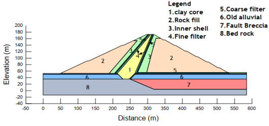
The inclined clay core dam cross section has been amended the slope of the outer shell with a ratio of 2H: 1V for upstream and 1.6H: 1V for downstream has been selected. This dam geometry includes 6 downstream berms and 2 upstream berms, each with a width of 4m. A core top width of 3m has been provided for the operation of building apparatus. And considering the actual site conditions, including the location of the fault breccia’s zone and economic factors, a clay core slope of 1V: 0.8H and 1V: 0.4H have been selected for the inclined clay core upstream and downstream respectively. The maximum dam cross-section of the modified dam cross-section with an inclined clay core (
Figure 3) are shown below.
Figure 3. Inclined Clay core Dam Geometry.
In
Figure 3, the old alluvial soil is present both upstream and downstream of the dam. Dam in Alluvial Foundation: Erosion of fine-graded soils through seepage can cause piping. It will result in differential settlement and seepage of the dam. Therefore, in an inclined clay core, the old alluvial soil has to be considered during analysis.
3.2. Comparison of Seepage Analysis
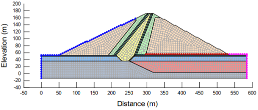
The number of finite elements has been adjusted based on the recommendation given by
| [21] | SEEP/W. 2012. “Seepage Modeling with SEEP / W.” GEO-SLOPE International Ltd., no. July: 1-199.
http://www.geo-slope.com |
[21]
engineering book where each discretized elements are clearly visible on (
Figure 4).
Figure 4. Finite element discretization and boundary condition applied for seepage analysis.
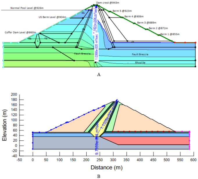
The flux through the dam body and the foundation has been computed for inclined clay core. Based on the computation, the total flux through the dam body and foundation is estimated to be 1.143×10⁻⁵ m3/sec/m. Among the total flux found, a flux of 9.76×10⁻⁸ m3/sec/m flows through the dam foundation, and 1.133×10⁻⁵ m3/sec/m flows through the dam body (
Figure 5B). Considering the crest length of the Middle Awash dam to be approximately 500m, the total volume of water seeping through the dam body and the foundation is estimated to be 0.0057m3/sec. For Comparison, the flux quantity calculated on the vertical clay core design prepared by the Ethiopia Water Works Design and Supervision Enterprise (ECDSWC, 2016) is 1.04×10
-5 m
3/sec and 4.18×10
-6 m
3/sec through the foundation and dam body respectively (
Figure 5A) so that the total volume of water seeps through the dam is expected to be 0.0073m
3 /sec.
Figure 5. A. Flux thorough dam body and foundation for Vertical core (ECDSWC, 2016) and B. For inclined clay core.
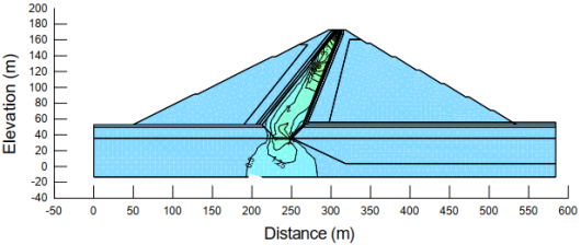
The hydraulic gradients are computed in the dam body and foundation for the Inclined core and the result varies in the range of 0.5 to 3.5 (
Figure 6). The vertical gradient inside the dam body and the foundation has varies between the ranges of 1.81×10⁻⁷ to 3.15×10⁻⁷.
Figure 6. Contours of horizontal gradient through dam body and foundation.
3.3. Comparison of Static Slope Analysis
3.3.1. Steady State Condition
The downstream embankment slope for both the vertical and inclined core options has been analyzed for steady state conditions when the reservoir is at normal pool level. A minimum factor of safety for inclined slopes was obtained from Geo-studio 2012 using a variety of analysis methods and comparison with the vertical clay core results, is presented in
Table 6 (ECDSWC, 2016). The factor of safety has been improved for the alternative due to the fact that the majority of the material with high shear strength is located on the downstream side, as a result of the inclination of the core material towards the upstream.
Table 6. Factor of safety of downstream slope at steady state condition.
Methods | Factor of Safety |
Vertical clay core | Inclined Clay Core | Allowable limit |
Morgenstern | 1.63 | 1.72 | 1.5 |
Ordinary | 1.59 | 1.69 | 1.5 |
Bishop | 1.63 | 1.72 | 1.5 |
Janbu | 1.59 | 1.69 | 1.5 |
3.3.2. End of Construction
The stability of both upstream and downstream slopes during end of construction has been analyzed and a minimum factor of safety was presented in
Table 7.
Table 7. Factor of safety both upstream and downstream slope at End of construction.
Methods | Factor of Safety |
Vertical clay core | Inclined Clay Core | Allowable limit |
D/S | U/S | D/S | U/S |
Morgenstern | 1.63 | 1.5 | 1.69 | 1.53 | 1.3 |
Ordinary | 1.62 | 1.49 | 1.67 | 1.52 | 1.3 |
Bishop | 1.62 | 1.5 | 1.64 | 1.53 | 1.3 |
Janbu | 1.61 | 1.49 | 1.66 | 1.53 | 1.3 |
3.3.3. Construction Stage
Based on the computation, the minimum factor of safety during construction stage is presented in
Table 8. For the downstream and upstream respectively.
Table 8. Factor of safety both upstream and downstream during construction stage.
Methods | Factor of Safety |
Vertical clay core | Inclined Clay Core | Allowable limit |
D/S | U/S | D/S | U/S |
Morgenstern | 1.63 | 1.57 | 1.501 | 1.59 | 1.3 |
Ordinary | 1.6 | 1.55 | 1.5 | 1.6 | 1.3 |
Bishop | 1.6 | 1.55 | 1.5 | 1.6 | 1.3 |
Janbu | 1.61 | 1.56 | 1.5 | 1.61 | 1.3 |
The upstream slope for revised design has been found to have a slight improved factor of safety as compare to the Vertical clay core and the downstream slope have a relatively less factor of safety as the downstream embankment slope because of relatively steeper. But the margin of safety computed for both upstream and downstream are still more than adequate when as compared to the minimum requirement suggested by to
| [23] | U.S. Army Corps of Engineers. 2003. “Engineering and Design, Slope Stability, Engineer Manual.” US Army Corps of Engineers, EM 1110-2-1902. |
[23]
. Furthermore, the mass of the downstream embankment slope potentially subject to failure is small and manageable.
3.3.4. Sudden Draw Down
During a sudden drawdown, the stabilizing effect of the water on the upstream face is abruptly lost, but the pore water pressures within the embankment may still remain high. As a result, the stability of the upstream face of the dam will be significantly reduced. During sudden drawdown conditions, materials with high hydraulic conductivity drain quickly, while materials with low hydraulic conductivity take a long time to drain. Therefore, a transient (time-dependent) analysis is required. For this study, it is assumed that the core material will have a slow drainage rate, while the other embankment materials will have a free drainage rate. Basically, to perform a transient seepage analysis, two sets of boundary conditions are required: an initial boundary condition and a transient boundary condition
. Initial boundary conditions are required to define pore water pressures throughout the model at the beginning of the transient analysis. For this analysis, the initial boundary condition is taken from the SEEP/W result, which shows a total head on the upstream embankment slope equal to the reservoir level at the initiation of drawdown. The initial pore water pressure required just before sudden drawdown has been obtained from the steady state condition. The minimum factor of safety during sudden drawdown in both inclined and vertical clay cores was presented in
Table 9.
Table 9. Factor of safety of Upstream slope during sudden drawdown.
Methods | Factor of Safety |
Vertical clay core | Inclined Clay Core | Allowable limit |
Morgenstern | 1.54 | 1.464 | 1.3 |
Ordinary | 1.34 | 1.42 | 1.3 |
Bishop | 1.54 | 1.464 | 1.3 |
Janbu | 1.42 | 1.44 | 1.3 |
3.5. Economical Comparison
For both the inclined clay core design and the vertical clay core design, an economic comparison of the Middle Awash dam's main operations has been calculated. The volume of the rock fill zone has resulted in an additional cost of 2.2 million US Dollar based on the estimated work quantity for the Embankment of vertical clay core geometry. An inclined clay core worth millions of US dollars. The cost of the inner shell and compacted clay core with special treatment work on the core foundation, however, could be lowered by 5.4 million US dollars in the case of inclined clay core geometry compared to the vertical clay core, which is the total of the inner shell and clay core. As shown in
Table 10, the inclined clay core has resulted in a savings of 3.2 million US dollars on the project from embankment work alone. In comparison to the vertical clay core geometry, the inclined clay core project cost has been lowered by 3% overall.
Table 10. Variation of activities due to clay core zone change.
Activity No | Description | Unit | Rate in USD | Quantity Variation | Amount in USD |
Addition | Omission |
1 | Embankment work | | | | | |
1.1 | Compacted Rockfill | m3 | 17.12 | 130011.1 | | 2,225,790.032 |
1.2 | Compacted Inner shell | m3 | 6.54 | | -101937 | -666,667.98 |
1.3 | Compacted clay core | m3 | 7.82 | | -603033.3 | -4,715,720.41 |
| Net Amount | | | | | -3,156,598.35 |
4. Discussion
The Middle Awash Dam was initially designed as a rock-fill dam with a vertical clay core, as previously discussed in this document. Due to the presence of fault breccia in the foundation, this design requires special treatment for the core's foundation (ECDSWC, 2016). To address this issue, an alternative approach was adopted by changing the core geometry from vertical to inclined, thereby eliminating the need for construction directly on the fault breccia. All necessary analyses have been conducted for this new clay core configuration.
A definitive evaluation of dam safety cannot be obtained solely from the rate of water flow through the dam body and foundation. Nonetheless, seepage through the embankment must be kept under control to the necessary degree. If the right filter material, drainage system, and relief wells are used, a leakage of 0.03 m3/sec through the embankment and dam foundation is usually acceptable
| [13] | Kutzner, Christian. 2018. “Earth and Rockfill Dams: Principles for Design and Construction.” Earth and Rockfill Dams: Principles for Design and Construction.
https://doi.org/10.1201/9780203758991 |
| [14] | Li, Changwen, Huabin Gao, Zhaoming Xu, and Yan Huang. 2021. “Sensitivity Analysis of Rock-Fill Dam Break Flood on Different Dam Break Durations.” Open Journal of Safety Science and Technology 11(3): 89-103.
https://doi.org/10.4236/ojsst.2021.113007 |
[13, 14]
. The amount of seepage loss through the dam body and foundation determined in this study is within the permitted range when compared to this recommendation. Consequently, it is determined that the newly suggested dam cross section's capacity to hold water is adequate. The inclined clay in this study and the original design created by ECDSWC have different total flux results for the dam's body and foundation. This is mainly because, given the limited supply of clay material within a reasonable transportation distance, the core thickness in this study is minimized to achieve maximum cost-effectiveness. As a result, while still satisfying the design specifications, the flow through the core is comparatively higher. Due to modifications, the flux calculated through the foundation for the inclined clay core is 9.76×10⁻⁸ m3/sec/m, which is significantly less than the original design calculated by 4.18×10⁻⁶ m3/sec/m (ECDSWC, 2016).
The risk of material erosion and piping is related to the hydraulic gradient inside the dam body. As a result, the hydraulic gradient at the interface between the core and the foundation and the core and the transition material must be regulated. It is advised that the hydraulic gradient for inclined core embankment dams not be greater than 4
| [13] | Kutzner, Christian. 2018. “Earth and Rockfill Dams: Principles for Design and Construction.” Earth and Rockfill Dams: Principles for Design and Construction.
https://doi.org/10.1201/9780203758991 |
[13]
and
| [23] | U.S. Army Corps of Engineers. 2003. “Engineering and Design, Slope Stability, Engineer Manual.” US Army Corps of Engineers, EM 1110-2-1902. |
[23]
. As a result, the calculated hydraulic gradient in this work complies with requirement I. The e. the interval between 0.5 and 3.5. Additionally, the vertical gradient within the foundation and dam body is significantly lower than the permitted exit gradient of 1 i.e. the 1.81×10
-7 to 3.15×10
-7. In order to prevent soil boiling and erosion on the dam foundation.
The inclined clay core section of the dam with the vertical clay core satisfies the minimum requirements under all loading conditions, according to the analysis that was done. The Morgenstern, Ordinary, Bishop, and Janbu method was used to perform the slope stability analysis. The slope stability analysis was carried out at various phases of construction, such as the end of construction, steady state condition, and sudden drawdown, based on the results obtained. It was found that all methods were safe when compared to the minimum allowable factor of safety set by the
| [23] | U.S. Army Corps of Engineers. 2003. “Engineering and Design, Slope Stability, Engineer Manual.” US Army Corps of Engineers, EM 1110-2-1902. |
[23]
. Therefore, the slope of the dam is safe in both vertical and inclined clay core geometry.
Geo Studio software results for the inclined core and (ECDSWC, 2016) for the vertical core indicate that the dam is safe against slope and seepage. However, because the thickness of the clay core is less than that of a vertical core, inclined clay core geometry is more cost-effective. The clay core becomes more appropriate for preventing seepage as its thickness increases. This study has demonstrated that the inclined clay core geometry is safe from seepage when the clay core thickness is thinner.
5. Conclusion
According to the Middle Awash dam's static analysis, changing the core geometry from vertical to inclined results in the following outcomes:
1) The amount of seepage through the dam body and foundation is found to be within acceptable limits compared to the standards.
2) It has been discovered that the downstream slope is stable under all loading conditions, including steady state conditions, the end of construction, and during construction.
3) The standard's minimal requirement is met by the factor of safety under all loading conditions. In a similar vein, it has been discovered that the upstream slope is stable under all loading conditions, including sudden drawdown, the end of construction, the construction stage, and during construction.
4) The minimum requirement recommended by the standard and guidelines is satisfied by the factor of safety under all loading conditions.
5) Additionally, the incline is based on the economic analysis of the project's primary Embankment work activities.
Abbreviations
ECDSWC | Ethiopia Construction Design and Supervision Work Corporation |
U/S | Upstream |
D/S | Downstream |
Acknowledgments
I would like to thank the project team workers of Ethiopian Construction Design and Supervision Work Corporation for providing me with detailed information about the dam.
Author Contributions
Chimdesa Regasa Kishe: Conceptualization, Data Curation, Formal Analysis, Investigation, Methodology, Resources, Software, Validation, Writing – review & editing
Data Availability Statement
Data cannot be made publicly available; reader should contact the corresponding author for details.
Conflict Interest
I declare that this title has no any conflict interest.
References
| [1] |
Assefa, Eleyas, Li Jian Lin, Costas I. Sachpazis, Deng Hua Feng, Sun Xu Shu, and Anthimos S. Anastasiadis. 2016. “Probabilistic Slope Stability Evaluation for the New Railway Embankment in Ethiopia.” Electronic Journal of Geotechnical Engineering 21(11): 4247-72.
|
| [2] |
Baye, Melese. 2020. “Construction Quality Control of the Dam, a Case of Kesem Dam (Ethiopia),” no. June.
|
| [3] |
Berhe, Tensay G. 2010. “Effect of Canyon Geometry and Ground Conditions on the Seismic Performance of Tendaho Earthfill Dam in Ethiopia.,” no. 4: 1-12.
|
| [4] |
Biswas, Asit K. 1968. “Discussion of ‘Influences on Selection of the Type of Dam.’” Journal of the Soil Mechanics and Foundations Division 94(2): 576-78.
https://doi.org/10.1061/jsfeaq.0001114
|
| [5] |
Chen, Bo, Li Zhang, Qiupei Qian, Yanhong Dou, and Zhuohao Ji. 2017. “Research on the Seepage Safety Monitoring Indexes of the High Core Rockfill Dam.” World Journal of Engineering and Technology 5(3): 42-53.
https://doi.org/10.4236/wjet.2017.53b006
|
| [6] |
Duncan, J. M., Stephen G Wright, and Brandon Thomas L. 2014. “Soil Strength and Slope Stability.” John Wiley & Sons 2(1): 37-72.
|
| [7] |
Farzampour, Armin. 2014. “Optimum Size for Clay Core of Alavian Earth Dam by Numerical Simulation.” Iranica Journal of Energy and Environment 5(3): 0-6.
https://doi.org/10.5829/idosi.ijee.2014.05.03.03
|
| [8] |
Gemeda, Desta. 2020. “The Alternative Design of Gidabo Embankment Dam by Introducing Asphalt Concrete Core: Southern Ethiopia.” International Journal of Scientific & Engineering Research 11(3): 1158-75.
http://www.ijser.org
|
| [9] |
GEO-SLOPE International Ltd. 2012. “Stability Modeling with Slope/W.” Stability Modeling with Slope/W, no. June: 213.
http://www.eng.uwo.ca/people/tnewson/Lectures/SLOPEW
Engineering Book.pdf
|
| [10] |
Griffiths, D V. 2015. “Slope Stability Analysis by Finite Elements: A Guide to the Use of Program slope64.” Geomechanics Research Center, Colorado School of Mines, no. September: 1-32.
http://www.icevirtuallibrary.com/doi/10.1680/geot.1999.49.3.387%0Apapers3://publication/doi/10.1680/geot.1999.49.3.387
|
| [11] |
Hasani, H., J. Mamizadeh, and H. Karimi. 2013. “Stability of Slope and Seepage Analysis in Earth Fills Dams Using Numerical Models (Case Study: Ilam DAM-Iran).” World Applied Sciences Journal 21(9): 1398-1402.
https://doi.org/10.5829/idosi.wasj.2013.21.9.1313
|
| [12] |
Khanna, Rajesh, Manoj Datta, and G. V. Ramana. 2014. “Influence of Inclination of Thin Core on Stability of Upstream Slope of Earth and Rockfill Dams.” Electronic Journal of Geotechnical Engineering 19 U: 6293-6305.
|
| [13] |
Kutzner, Christian. 2018. “Earth and Rockfill Dams: Principles for Design and Construction.” Earth and Rockfill Dams: Principles for Design and Construction.
https://doi.org/10.1201/9780203758991
|
| [14] |
Li, Changwen, Huabin Gao, Zhaoming Xu, and Yan Huang. 2021. “Sensitivity Analysis of Rock-Fill Dam Break Flood on Different Dam Break Durations.” Open Journal of Safety Science and Technology 11(3): 89-103.
https://doi.org/10.4236/ojsst.2021.113007
|
| [15] |
López-Querol, S., and P. J. M. Moreta. 2008. “Performance of Heterogeneous Earthfill Dams under Earthquakes: Optimal Location of the Impervious Core.” Natural Hazards and Earth System Science 8(1): 9-18.
https://doi.org/10.5194/nhess-8-9-2008
|
| [16] |
Mulat, Asegdew G., and Semu A. Moges. 2014. “Assessment of the Impact of the Grand Ethiopian Renaissance Dam on the Performance of the High Aswan Dam.” Journal of Water Resource and Protection 6(6): 583-98.
https://doi.org/10.4236/jwarp.2014.66057
|
| [17] |
Nayebzadeh, R., and M. Mohammadi. 2011. “The Effect of Impervious Clay Core Shape on the Stability of Embankment Dams.” Geotechnical and Geological Engineering 29(4): 627-35.
https://doi.org/10.1007/s10706-011-9395-z
|
| [18] |
Njiru, Fausta Mbura, and David N Siriba. 2018. “Site Selection for an Earth Dam in Mbeere,” 113-33.
https://doi.org/10.4236/gep.2018.67009
|
| [19] |
Rashidi, Mohammad, and S Mohsen Haeri. 2017. “Journal of Rock Mechanics and Geotechnical Engineering Evaluation of Behaviors of Earth and Rock Fi Ll Dams during Construction and Initial Impounding Using Instrumentation Data and Numerical Modeling.” Journal of Rock Mechanics and Geotechnical Engineering 9(4): 709-25.
https://doi.org/10.1016/j.jrmge.2016.12.003
|
| [20] |
Sandra, Dra, Elizondo Argueta, Niels H Wacher, Mara Silva, Leticia Valdez, Miguel Cruz, Rita A Gómez-Díaz, et al. 2016. “No Analysis of the co-dispersion structure of health-related indicators, the center of the subject's sense of health, and the elderly people living at home. Title.” Revista CENIC. Ciencias Biológicas 152 (3): 28.
|
| [21] |
SEEP/W. 2012. “Seepage Modeling with SEEP / W.” GEO-SLOPE International Ltd., no. July: 1-199.
http://www.geo-slope.com
|
| [22] |
Tadesse, Abebe Arega, and Bikila Teklu. 1999. “School of Graduate Studies Construction Quality Monitoring of Embankment Dams Using Pore Water Pressure, the Case of Kesem Dam Approved By Board of Examiners.”
|
| [23] |
U.S. Army Corps of Engineers. 2003. “Engineering and Design, Slope Stability, Engineer Manual.” US Army Corps of Engineers, EM 1110-2-1902.
|
Cite This Article
-
APA Style
Kishe, C. R. (2026). Comparison of Stability Analysis of Rockfill Dams with Vertical and Inclined Clay Cores: A Case Study of the Middle Awash Dam, Ethiopia. American Journal of Water Science and Engineering, 12(1), 1-12. https://doi.org/10.11648/j.ajwse.20261201.11
 Copy
|
Copy
|
 Download
ACS Style
Kishe, C. R. Comparison of Stability Analysis of Rockfill Dams with Vertical and Inclined Clay Cores: A Case Study of the Middle Awash Dam, Ethiopia. Am. J. Water Sci. Eng. 2026, 12(1), 1-12. doi: 10.11648/j.ajwse.20261201.11
Copy
|
Download
AMA Style
Kishe CR. Comparison of Stability Analysis of Rockfill Dams with Vertical and Inclined Clay Cores: A Case Study of the Middle Awash Dam, Ethiopia. Am J Water Sci Eng. 2026;12(1):1-12. doi: 10.11648/j.ajwse.20261201.11
Copy
|
Download
-
@article{10.11648/j.ajwse.20261201.11,
  author = {Chimdesa Regasa Kishe},
  title = {Comparison of Stability Analysis of Rockfill Dams with Vertical and Inclined Clay Cores: A Case Study of the Middle Awash Dam, Ethiopia},
  journal = {American Journal of Water Science and Engineering},
  volume = {12},
  number = {1},
  pages = {1-12},
  doi = {10.11648/j.ajwse.20261201.11},
  url = {https://doi.org/10.11648/j.ajwse.20261201.11},
  eprint = {https://article.sciencepublishinggroup.com/pdf/10.11648.j.ajwse.20261201.11},
  abstract = {This study conducted slope and seepage stability analysis of a rock fill dam by comparing the clay core geometry. The core geometry in this study has been changed from a vertical to an inclined arrangement, and all analyses have been conducted are compared with the original design. The geometry of the inclined clay core dam was fixed and checked for static loading conditions. The analysis has been conducted using numerical modeling software called GEO-Studio 2012. Based on calculations, the flux through the dam with an inclined clay core is 0.0057 m3/sec, while the flux from the original dam with a vertical core is 0.0073 m3/sec. The safety factors for the downstream slope during steady state, sudden drawdown, end of construction, and the construction stage are 1.72, 1.56, 1.53, 1.64, and 1.59, respectively. These values were obtained from the original dam design with a vertical clay core, and the corresponding safety factors are 1.63, 1.54, 1.63, and 1.57, respectively. Therefore, the geometry of the clay core is considered safe based on the allowable limit factor of safety and seepage. In addition to this, the inclined clay core section was found to be significantly more Economical compared to the vertical clay core.},
 year = {2026}
}
Copy
|
Download
-
TY  - JOUR
T1  - Comparison of Stability Analysis of Rockfill Dams with Vertical and Inclined Clay Cores: A Case Study of the Middle Awash Dam, Ethiopia
AU  - Chimdesa Regasa Kishe
Y1  - 2026/02/27
PY  - 2026
N1  - https://doi.org/10.11648/j.ajwse.20261201.11
DO  - 10.11648/j.ajwse.20261201.11
T2  - American Journal of Water Science and Engineering
JF  - American Journal of Water Science and Engineering
JO  - American Journal of Water Science and Engineering
SP  - 1
EP  - 12
PB  - Science Publishing Group
SN  - 2575-1875
UR  - https://doi.org/10.11648/j.ajwse.20261201.11
AB  - This study conducted slope and seepage stability analysis of a rock fill dam by comparing the clay core geometry. The core geometry in this study has been changed from a vertical to an inclined arrangement, and all analyses have been conducted are compared with the original design. The geometry of the inclined clay core dam was fixed and checked for static loading conditions. The analysis has been conducted using numerical modeling software called GEO-Studio 2012. Based on calculations, the flux through the dam with an inclined clay core is 0.0057 m3/sec, while the flux from the original dam with a vertical core is 0.0073 m3/sec. The safety factors for the downstream slope during steady state, sudden drawdown, end of construction, and the construction stage are 1.72, 1.56, 1.53, 1.64, and 1.59, respectively. These values were obtained from the original dam design with a vertical clay core, and the corresponding safety factors are 1.63, 1.54, 1.63, and 1.57, respectively. Therefore, the geometry of the clay core is considered safe based on the allowable limit factor of safety and seepage. In addition to this, the inclined clay core section was found to be significantly more Economical compared to the vertical clay core.
VL  - 12
IS  - 1
ER  -
Copy
|
Download