Abstract
Turbodrill, as one of the extremely important downhole power operation tools in the field of oil and gas field exploration and development, has a wide range of application conditions and requirements. Among them, the blade grid of turbodrill, as the core component of turbodrill, directly affects the downhole operation performance of the drilling tool. However, the overall structural design of existing turbodrill tools requires the gradual derivation of blade geometry parameters based on theoretical formulas and repeated calibration. The overall design workload is large, the calculation steps are complex, and the overall design cycle is long. The existing traditional design methods have prominent problems. Therefore, in order to effectively improve the overall design efficiency and calculation accuracy of turbodrill, an innovative parametric design method for the overall structure of turbodrill blade cascade is proposed. Based on the theory of univariate flow and the modular parameterization design approach, a hierarchical framework for the overall design module and sub modules of the turbodrill blade cascade was established, and a parameter relationship network diagram was formed for the corresponding parameters in the design process of the stator and rotor of the guide vane cascade; And based on the modular design process, a parametric design and operation fitting system was built. At the same time, a program driven computer-aided design software was used to generate the overall three-dimensional structural diagram, and finally a parameterized design and operation platform for the overall structure of the turbine blade was obtained, which is easy to design and optimize. Based on the built design and operation platform, the overall structure design of the turbine blade was completed, and the feasibility of the design method and operation platform was verified using finite element calculation method. The research results show that the innovative parameterized design method and computing platform for the overall structure of turbine blade cascades effectively solve the problem of large design workload in the complex, diverse, and flexible design process of turbine blade cascades. The calculation accuracy has been improved by about 20%, and the overall design efficiency has been increased by more than 35%. The promotion and application of this innovative parameterized design method for the overall structure of turbine drilling tool blade cascades will greatly improve the design efficiency and calculation accuracy of downhole turbine drilling tool structures, which is of great significance for promoting the technological upgrading of China's intelligent manufacturing industry.
Keywords
Turbine, Cascade, Stator and Rotor, Parameterization, Structural Design
1. Preface
In recent years, due to the extensive exploitation and consumption of conventional oil and gas resources globally, coupled with the energy demand driven by rapid socio-economic development, countries worldwide are actively exploring and developing unconventional oil and gas resources such as those in high-temperature, high-pressure, and ultra-deep wells. Consequently, there is an urgent need to design and develop downhole operation tools that are suitable for complex working conditions such as high temperature, high pressure, and ultra-deep wells. Among these, turbodrills serve as crucial power tools for drilling and developing high-temperature, high-pressure, highly deviated, and ultra-deep oil and gas wells. They can be paired with novel technologies like coiled tubing, PDC bits, and centralizers to achieve efficient drilling operations under complex conditions in oil and gas fields. These turbodrills exhibit outstanding advantages such as good resistance to high temperature and pressure, high mechanical speed, high stability, good directionality, and strong adaptability to supporting technologies.
Currently, turbodrills have developed into one of the most widely used downhole power drill tools in the field of oil and gas field development. Their extensive application in petroleum and natural gas engineering has greatly improved drilling quality and speed, reduced well construction cycles and operational costs, and achieved outstanding economic benefits in oil and gas field development
| [1] | Lin Yuanhua, Zeng Dezhi, Li Runfang, Huang Wanzhi, Shi Taihe Research on New Blade Profile of Turbodrill and Its Computer Aided Design [J] Journal of Chongqing University (Natural Science Edition), 2004, 02: 24-27+39. |
| [2] | Calnan, D. (Cornerstone Natural Resources); Seale, R.; Beaton, T. Identifying applications for turbo-drilling and evaluating historical performances in North [C]. Journal of Canadian Petroleum Technology, v 46, n 6, p 34-39, June 2007 America. |
| [3] | Gong Pan, Wang Peng, Zhang Chen, Feng Ding, Tu Yiliu. Design and Research on Twisted Blade Shape of Turbodrill [J]. Machine Tool and Hydraulic, 2019, 47 (19): 153-158. |
[1-3]
. However, as the core component of turbodrills, the turbine blade cascade has a complex blade structure, and the overall structural design requires the gradual derivation of turbine cascade geometric parameters based on theoretical formulas and repeated calibration. The overall design workload is substantial, and the trial calculation steps are cumbersome. Therefore, in order to reduce the design workload of design staff and effectively improve the overall design efficiency and calculation accuracy of turbodrills, this paper focuses on combining one-dimensional flow theory and modular parametric design ideas to propose an innovative new method for the parametric design of the overall structure of turbodrill turbine blade cascades. Firstly, based on the one-dimensional flow theory of turbine design and modular parametric design ideas, a hierarchical relationship framework between the overall design module and sub-modules of the turbodrill turbine blade cascade is established, forming a mathematical operation relationship network diagram corresponding to various parameters in the design process of the inducer and rotor of the turbine blade cascade. Then, based on the modular design process, a parametric design and operation fitting system is built, and the overall three-dimensional structural diagram of the turbodrill turbine blade cascade is generated through program-driven computer-aided design software. Finally, by integrating the overall parametric programming technology of the turbodrill turbine blade cascade with the operation method of three-dimensional auxiliary design software, a parametric design operation platform for the overall structure of the turbine blade cascade is finally obtained, which can directly generate the overall three-dimensional structural diagram of the turbine blade cascade by changing program parameters. Based on this platform, the overall structural design and finite element calculation performance verification analysis of the turbine blade cascade are completed. A new flexible design method for the turbine blade cascade structure is formed, which is easy to design and optimize, effectively improving the design efficiency and calculation accuracy of the turbine structure. This is of great significance for promoting the technological upgrading of China's intelligent manufacturing industry.
2. Turbodrill Blade Cascade Design
A turbodrill is a downhole power tool assembly that converts the hydraulic energy of drilling mud fluid into mechanical energy. It primarily consists of a housing, thrust bearing, main shaft, turbodrill vane assembly, turbine body, and centralizer bearing. The turbodrill vane, as the core power output component of the turbodrill, directly affects its operational performance. It mainly converts the kinetic energy of high-speed drilling mud fluid, which flows through the internal flow passage of the turbine main shaft and enters the guide vane assembly during the turbodrill's operation, into mechanical energy to output rotational torque, ultimately driving the drill bit to rotate and break rock for drilling.
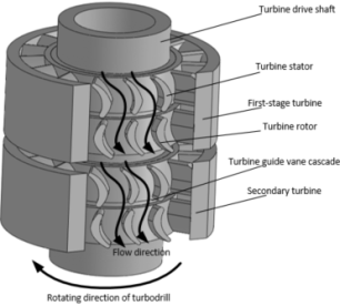
As a typical axial-flow turbomachinery, turbodrills can be classified into single-stage and multi-stage turbine pairs based on the number of stages driving the turbine within the assembly. The turbine cascade of a turbodrill is the core component determining its performance. The pressure and suction surface profiles of the turbine cascade blades determine the hydraulic performance of the flow guide. Therefore, accurate design of the turbine cascade shape is crucial. The turbine cascade of a turbodrill adopts an axial flow transmission form and is mainly composed of a turbine stator, a turbine rotor, and blades. The fluid flowing through the flow guide cascade is guided by the turbine stator and then impacts the blades of the turbine rotor, driving the rotor mounted on the turbine drive shaft to rotate. The fluid then flows through the rotor blades to the next-stage turbine. Multiple (or single) turbines are coupled to jointly transmit rotational torque to the turbine drive shaft, providing power for the downhole turbodrill (as shown in
Figure 1). Traditional design methods for the shape of turbodrill cascades require gradual derivation of cascade geometric parameters based on theoretical formulas and repeated calibration. The overall design workload is heavy, the trial calculation steps are complex, and the overall efficiency is low. Therefore, this paper develops an innovative parametric and efficient design method for the overall structure of turbodrill cascades, which enables program-driven computer-aided software to automatically complete the overall structural design with high quality.
Figure 1. Schematic diagram of two-stage turbine blade structure.
Currently, the turbine drill blade cascade is predominantly of a planar form, meaning that the turbine stator and rotor blades have consistent blade profiles along the radial circumferential surface. To carry out the structural design of the turbine drill blade cascade, it is necessary to first calculate the turbine blade cascade flow parameters and turbine structural dimensions based on the turbine's operating conditions and dimensional parameters. Then, according to the one-dimensional flow theory formulas and inlet and outlet fluid flow structural parameters, the geometric parameters of the turbine blade cascade and the turbine blade profile design calculations are completed. Finally, the blade pressure surface and suction surface profile curve equations are obtained, and the overall structure of the turbine drill blade cascade is determined. In the design of the turbine drill blade cascade, by changing the inlet and outlet structural angles of the stator and rotor blades, the profile curves, flow channels, and impact angle characteristics of the blade pressure surface and suction surface of the blade cascade are affected, thereby determining the hydraulic performance of the turbine.
2.1. Analysis of Cascade Flow Model
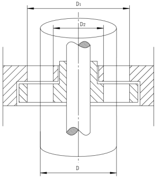
The key components for power conversion in the turbine drill cascade are the stator and rotor blade discs. The fluid flow is guided by the stator blades and then impacts the rotor blades to rotate, thereby driving the turbine main shaft to output torque. The fluid flow at the rotor outlet continues to converge into the downstream turbine stator guide vane cascade until the lowest-level turbine outputs the superimposed torque. Based on the principle of the turbine drill cascade, a turbine cascade flow model is constructed as shown in
Figure 2, where D1 is the outer diameter of the cascade, D2 is the inner diameter of the cascade, and D is the calculated diameter of the cascade. Based on the basic assumptions of the one-dimensional fluid theory for turbine drill design, the following calculation formulas can be derived:
 (1)
(1)  (2)
(2)  (3)
(3) In the formula: u represents the circumferential velocity of the fluid flow at the calculated diameter of the cascade, n denotes the rotational speed of the main shaft, Q signifies the fluid flow rate entering the cascade, ρ stands for the fluid density, R indicates the calculated radius of the cascade, and and represent the tangential components of the absolute velocity of the fluid flow at the inlet and outlet of the cascade, respectively.
Figure 2. Schematic diagram of cascade structure of stage turbine.
2.2. Analysis of Blade Design Parameters in Blade Cascade
In the design of cascade blade shapes, the blade profiles are arranged at the same spacing and angle along the frontal line to form a cascade. The mid-arc line of the blade is the trajectory of the center of the inscribed circle that is tangent to both the pressure and suction surfaces of the same blade. The midline of the flow passage is the trajectory of the center of the inscribed circle that is tangent to both the pressure and suction surfaces of the fluid passage
| [4] | Computational procedure for optimum shape design based on chained Bezier surfaces parameterization [J]. Damir Vucina; Zeljan Lozina; Igor Pehnec. Engineering Applications of Artificial Intelligence, 2012. |
| [5] | Design of high-efficiency turbomachinery blades for energy conversion devices with the three-dimensional prescribed surface curvature distribution blade design (CIRCLE) method [J]. T. Korakianitis; I. A. Hamakhan; M. A. Rezaienia; A. P. S. Wheeler; E. J. Avital; J. J. R. Williams. Applied Energy, 2011(1). |
| [6] | Status and prospects of exploration and exploitation key technologies of the deep petroleum resources in onshore China [J]. Genshun Yao; Xianzhu Wu; Zandong Sun; Chunhao Yu; Yunhua Ge; Xianyou Yang; Long Wen; Chao Ni; Xiaodong Fu; Jianyong Zhang. Journal of Natural Gas Geoscience, 2018(1). |
[4-6]
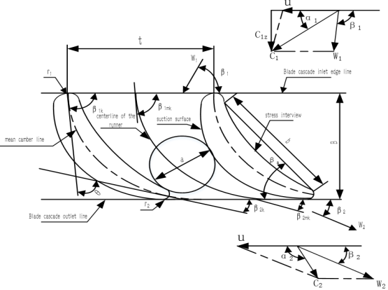
. The inlet and outlet structural angles of the turbine cascade rotor blades are β1k and β2k, while the inlet and outlet structural angles of the midline of the flow passage are β1mk and β2mk. Similarly, the inlet and outlet structural angles of the stator blades can be expressed as α1k and α2k (the structural design is shown in
Figure 3). The structural characteristic parameters of the turbine cascade include the radii of the blade leading and trailing edges, r1 and r2, the blade chord length, b, the installation angle of the rotor blades, βs, the cascade pitch, t, the cascade width, B, the throat width of the cascade, a, and the blade profile twist angle, θ. When fluid flows through the cascade, the direction of fluid flow is represented by the inlet angle β1 (α1) and the outlet angle β2 (α2). The relative velocities of the inlet and outlet fluid flows are W1 and W2, the absolute velocities of the inlet and outlet fluid flows are C1 and C2, and the circumferential velocity of the fluid flow is u. The inlet and outlet fluid flow angles of the cascade are not necessarily equal to the inlet and outlet structural angles. Generally, the following two parameters are used to represent the relationship between the fluid flow direction and the geometric parameters of the cascade:
 (4)
(4) In the formula, i represents the rotor blade incidence angle, and δ represents the rotor blade lag angle. They are closely related to the blade lift coefficient and hydraulic loss. Similarly, the incidence angle and lag angle of the stator blade can also be calculated.
Figure 3. Schematic diagram of blade shape parameters for cascade blades.
After flowing through the turbine blade cascade and entering the stator guide, the fluid's relative velocity is equal to its absolute velocity due to the non-rotating stator. Therefore, the velocity magnitude at the stator outlet is determined by the axial component velocity. As the stator outlet is very close to the rotor inlet, the absolute velocity of the fluid at the stator outlet is equal to that at the rotor inlet. This can be calculated as follows:
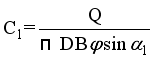 (5)
(5) 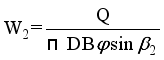 (6)
(6) In the formula, C1 represents the absolute velocity of fluid flow at the outlet of the cascade stator, Q denotes the working flow entering the cascade, B signifies the cascade width (or the radial width of the blade), D stands for the calculated diameter of the cascade, is the reduction coefficient of the blade cross-section, is the inlet angle of the cascade stator, and is the outlet angle of the cascade rotor.
In addition, the profile design of the pressure and suction surfaces of the turbodrill cascade blades is crucial in the overall design of the cascade. Therefore, based on meeting the geometric parameters and flow characteristics of the blades, a profile design featuring a continuous curvature of a high-order quintic polynomial is constructed. The profile curves of the pressure and suction surfaces of the blades are constructed as follows:

and

, Its polynomial form is as follows:
 (7)
(7)  (8)
(8) The design of the turbine drill blade cascade structure must meet the design requirements of the geometric structure of the cascade blades and the hydraulic theory parameters. It is necessary to fully understand and calculate the structural parameters, and determine the profile curve equations of the pressure and suction surfaces of the cascade blades, in order to finally complete the overall structure of the turbine drill blade cascade.
3. Basic Idea of Parametric Design
The so-called parametric design technology primarily involves transforming quantitative information in the design object into variables, making it adjustable parameters. By utilizing geometric constraints and engineering equations and relationships, an explicit correspondence between the variable parameters and the geometric shape characteristics of the design object is established. When different values are assigned to the variable parameters, new target geometric shape characteristics can be achieved, resulting in a cluster of design objects with similar shapes or functions
| [7] | Computer-aided design of horizontal axis turbine blades [J]. F. Pérez-Arribas; I. Trejo-Vargas. Renewable Energy, 2012. |
| [8] | Feng Jin, Fu Daliang. New Method for Shape Design of Turbine Blades in Turbodrill Tools [J]. Petroleum Machinery, 2000 (11): 9-12+3. |
| [9] | Feng Chao, Xu Huajing, Huang Jian, Xia Chengyu, Liu Jian, Qian Liqin. Structural parameter optimization and fluid simulation of turbine hydraulic oscillator [J]. Science, Technology and Engineering, 2022, 22 (09): 3525-3531. |
| [10] | Jorge D. Camba, Manuel Contero. Pedro Company. Parametric CAD modeling: An analysis of strategies for design reusability [J]. Computer-Aided Design, v74, p18–31, May 2016. |
| [11] | Kubo, Masaaki; Ejiri, Eiji; Kumada, Haruo; Ishii, Yoshihiko. Improvement of prediction accuracy for torque converter performance: one-dimensional flow theory reflecting the stator blade geometry [J]. JSAE review, v 15, n 4, p 309-314, Oct 1994. |
| [12] | Lu, Xiu-Quan; Chu, Ya-Xu; Cai, Wei; Ma, Wen-Xing; Song, Jian-Jun. Predicting method for partial-filling performance of hydrodynamic retarder based on one-dimensional flow beam theory [J]. Jilin Daxue Xuebao (Gongxueban)/Journal of Jilin University (Engineering and Technology Edition), v 41, n 4, p 988-992, July 2011. |
[7-12]
. The basic methods of parametric design include program-driven and dimension-driven. Program-driven involves analyzing the geometric model characteristics of the design object, determining the main parameters of the design object and the mathematical operation relationships between various dimensions, and inputting these relationships into the program. This allows for the generation of the required design object by simply inputting a few parameter values during object design
| [13] | Sun Zhili, Ji Guangzhen, Yan Yutao, Yang Qiang. Parametric Design Technology for Mechanical Products [M]. Beijing: National Defense Industry Press, 2014, 01. |
| [14] | Javier Monedero, Zhang Tinghua. Parametric Design: Overview and Some Experience [J]. Urban Environmental Design, 2010, 10: 20-24. |
| [15] | Experimental study of circulation flow in a light dispersion hydrocyclone [J]. Yi Liu; Qiang Yang; Peng Qian; Hua-lin Wang. Separation and Purification Technology, 2014. |
| [16] | Fluid Flow Investigation through Small Turbodrill for Optimal Performance [J]. Amir Mokaramian; Vamegh Rasouli; Gary Cavanough. Mechanical engineering research, 2013. |
| [17] | Tribological behavior of PTFE nanocomposite films reinforced with carbon nanoparticles [J]. Jeong-Yeop Lee; Dong-Phill Lim; Dae-Soon Lim. Composites Part B, 2006. |
[13-17]
. Furthermore, dimension-driven is an extension of program-driven, with the basic idea being to generate the involved base graph by the application. The dimensions of this graph are labeled with a series of identifiers, which are input or interactively input by the user during editing, thus generating the user's design object
| [18] | Optimization design for turbodrill blades based on response surface method [J]. Xiaodong Zhang; Shimin Yu; Yan Gong; Yilan Li. Advances in Mechanical Engineering, 2016. |
| [19] | Computational procedure for optimum shape design based on chained Bezier surfaces parameterization [J]. Damir Vucina; Zeljan Lozina; Igor Pehnec. Engineering Applications of Artificial Intelligence, 2011(3). |
| [20] | Hydrodynamically detailed performance analysis of a mixed-flow waterjet pump using computational fluid dynamics [J]. Oh, H W; Yoon, E S. Proceedings of the Institution of Mechanical Engi, 2008(C9). |
[18-20]
. Parametric design technology enables the design object to have flexibility that is easy to modify, allowing for rapid modification and generation of the design object according to the requirements specified by the designer. This greatly improves design efficiency and quality, facilitating serialized design.
Therefore, in view of the current situation where the overall structural design of traditional turbodrill cascades involves a large amount of work and complex theoretical calculation and calibration steps, in order to effectively improve the overall design efficiency and calculation accuracy of turbodrills, a new parametric design method for the overall structure of turbodrill cascades is proposed below, which fully integrates parametric design technology.
4. Parametric Structural Design of Turbodrill Blade Cascade
4.1. Overall Design
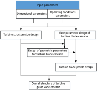
Based on the overall structure of the turbodrill cascade, and under the premise of meeting the turbine operating condition parameters and the design parameters required by cascade hydraulics theory, a turbodrill cascade design system and a turbine stator-rotor overall design module have been constructed. These include turbine structure size design, turbine cascade flow parameter design, turbine cascade geometric parameter design, and turbine blade profile design. Data transfer interface relationships between each module have been established, forming the overall design process shown in
Figure 4. During the structural modeling design process of the turbodrill cascade, the turbine cascade flow parameters and turbine structure dimensions are first calculated based on the turbine's operating conditions and dimensional parameters. Then, the turbine cascade geometric parameters and turbine blade profile design calculations are completed based on the one-dimensional flow theory formulas and inlet and outlet fluid flow structure parameters. Finally, the blade pressure surface and suction surface profile curve equations are obtained, and the overall structure of the turbodrill cascade is determined.
Figure 4. Overall design process of turbodrill blade array.
4.2. Operational Logic
Based on the classical one-dimensional flow theory of turbodrill design, the four main design modules in the overall structural design process of turbodrill cascades (i.e., turbine structure size design, turbine cascade flow parameter design, turbine cascade geometric parameter design, and turbine blade profile design) are refined and the transfer relationships between the modules are sorted out, thereby forming a mathematical operation relationship network among the various parameters involved in the structural design of key components of turbodrill cascades.
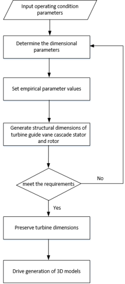
Firstly, based on the operational conditions required for turbine design (including turbine working flow rate, rotational speed, and torque), the design dimensions of the turbine drill blade cascade are determined (including the outer diameter of the turbine cascade stator, the inner diameter of the rotor, the blade height, and the inner and outer diameters of the cascade flow passage). Relevant empirical parameter values for theoretical calculations are set (including the wall thicknesses of the inner and outer rings of the cascade stator and rotor, axial clearance, relative blade pitch, wedge angles of the leading and trailing edges, radii of the leading and trailing edges, mud flow density, and turbine working volumetric efficiency). Then, mathematical relationships between various production factors are established based on theoretical calculation formulas. Software programs are used to drive each module in the overall turbine design to generate the structural dimensions of the turbine stator and rotor. The blade shapes of the turbine stator and rotor are checked to ensure they meet the design requirements. If they do, the structural dimensions of the turbine stator and rotor are saved; if not, the dimensional parameters are redefined, and the turbine stator and rotor structural dimensions are generated again until the design requirements are met. Finally, based on the determined structural component dimensions generated by each module in the overall structural design of the turbine drill blade cascade, a three-dimensional model of the overall structure of the turbine drill blade cascade that meets the operational conditions and design parameters of the turbine blade cascade is automatically generated through computer-aided software, completing the overall design and calculation.
4.3. Programming
Based on the mathematical operational relationships between various parameters constructed from detailed design, the four main modules in the overall structural design of the turbodrill cascade are encoded to achieve programmatic design and correlation between modules. Combining program-driven and dimension-driven methods in the parameterized design approach, according to the technical parameter requirements and operating condition adaptation conditions of the designed turbine, a set of parameter values is input after completing program building in the programming software, driving each module to design the structural dimensions of turbine cascade components, flow parameters of the turbine cascade, geometric parameters of the turbine cascade, and turbine blade surface equations. Furthermore, the programming-related computer-aided software is used to automatically generate geometric shape feature graphics of the overall structure of the designed turbine cascade, thus achieving flexible design that is easy to modify for the overall structure and key components of the turbodrill cascade.
5. Application Analysis of Parametric Design Method for Turbine Stator and Rotor
The turbodrill cascade parametric design system constructed in this paper is based on a direct parametric design method that focuses on the construction process. It is suitable for flexible design of integral components such as turbine cascades, stators, rotors, and blade discs with different structural dimensions. In the parametric design system, various geometric dimensions and flow parameters are parameterized quantitatively. During program execution, when different values are assigned to the parameters, the corresponding overall and component structural models of the turbodrill cascade are automatically updated. The application process of structural parameterization for turbodrill cascades is shown in
Figure 5 below.
Figure 5. Turbine rotor and stator parameterization flowchart.
Taking the design of the rotary reaming hydraulic drive turbine, which is widely used in the field of oil and gas exploration and development, as an example, the application process of parametric design for turbine drill blade cascade is elaborated. The design operating conditions and geometric dimension requirements for the rotary reaming hydraulic drive turbine are shown in
Table 1 below.
Table 1. Design condition and size requirement parameter table.
Parameter name/symbol | Value/Unit | Parameter name/symbol | Value/Unit |
Work flow Q | 2m3/min | Stator outer diameter d1 | 160mm |
Rotational speed n | 1000r/min | Rotor inner diameter d2 | 75mm |
Torque T | 800Nm | Outer diameter of flow channel D1 | 135mm |
Blade height S | 12mm | Inner diameter of flow channel D2 | 95mm |
1) Input operating condition parameters. According to the design operating condition requirements, input operating condition parameters: working flow rate, rotational speed, and torque;
2) Determine the dimensional parameters. According to the dimensional design requirements, input the dimensional parameters: stator outer diameter, rotor inner diameter, blade height, turbine stage height, flow passage inner diameter, and flow passage outer diameter;
3) Set empirical parameter values. Based on empirical values, the wall thicknesses of the stator inner ring and rotor outer ring are set to 2mm and 1.5mm, respectively, with axial clearances of 3mm and 5mm, respectively. On the other hand, the relative pitch of the turbine blades is set to 0.742, with the wedge angles of the leading and trailing edges set to 20° and 11°, respectively, and the radii of the leading and trailing edges set to 0.8mm and 0.4mm, respectively. Additionally, the mud density is set to 1×10³ kg/m3, and the volumetric efficiency is set to 0.9.
4) Generate turbine stator and rotor structural dimensions. Based on the established mathematical relationships between various parameters, utilize software programs to drive each module in the overall turbine design to generate turbine stator and rotor structural dimensions, namely: turbine structural dimensions, turbine cascade flow parameter results, turbine cascade geometric parameter results, and turbine stator and rotor blade profile dimensions.
5) Determination of turbine blade cascade stator and rotor dimensions. Based on the generated turbine stator and rotor structural dimensions, verify whether the turbine stator and rotor blade profiles meet the design requirements. If they meet the requirements, save the turbine stator and rotor structural dimensions; if not, re-determine the dimensional parameters and generate the turbine stator and rotor structural dimensions again until they meet the design requirements.
6) Drive the generation of a three-dimensional model of the overall structure of the turbine drill blade cascade. Based on the structural dimensions of the turbine stator and rotor generated by each module in the overall turbine design, automatically generate the geometric shape feature model of the designed turbine stator and rotor through computer-aided software.
Based on the parameterized design and fitting system process of the turbine structure, the dimensions of each part of the rotary reaming hydraulic drive turbine are calculated and are shown in
Tables 2 and 3 below.
Table 2. Structural dimensions of turbine stator and rotor.
Parameter name/symbol | Value/Unit | Parameter name/symbol | Value/Unit |
Blade inner diameter D1 | 95mm | Stator inner diameter d2 | 91mm |
Blade outer diameter D2 | 135mm | Stator outer diameter d1 | 160mm |
Blade centerline diameter D | 115mm | Rotor inner diameter d4 | 75mm |
Blade radial width B | 20mm | Rotor outer diameter d5 | 138mm |
Blade axial width S | 12mm | Radial clearance △r | 1mm |
Thickness of stator inner ring t1 | 2mm | The clearance δ1 between a pair of turbine stators and rotors | 3mm |
Thickness of rotor outer ring t2 | 1.5mm | The clearance δ2 between two sets of turbine stators and rotors | 5mm |
Table 3. Turbine cascade and blade parameters table.
Parameter name/symbol | Value/Unit | Parameter name/symbol | Value/Unit |
Blade chord length b | 14.33mm | Leading edge wedge angle φ1 | 20° |
Blade row pitch t | 10.63mm | Trailing edge wedge angle φ2 | 11° |
Blade height S | 12mm | Rotor blade inlet structural angle β1k | 100.53° |
Leading edge radius r1 | 0.8mm | Rotor blade outlet structural angle β2k | 33.88° |
Trailing edge radius r2 | 0.4mm | Stator vane inlet structural angle α1k | 33.88° |
Blade installation angle βm | 56.9° | Stator vane exit structure angle α2k | 100.53° |
Based on the above parameters, the inlet and outlet flow structure parameters of the turbodrill cascade can be determined. Subsequently, the profile curve equations for the pressure and suction surfaces of the blades can be obtained as follows:
 (9)
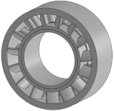
(9) Figure 6. S Turbodrill blade stator rotor and overall structure.
Based on the calculation results of the above parameters, and through system programming to drive computer-aided software, the overall structure and key components of the designed turbine drill guide vane cascade are automatically generated as shown in
Figure 6. After calculation, compared to the traditional turbine drill vane cascade modeling design method, which involves gradually deriving the vane cascade geometric parameters using theoretical formulas and repeated trial calculations, the overall design efficiency is improved by more than 35% using the computer-aided parametric design method.
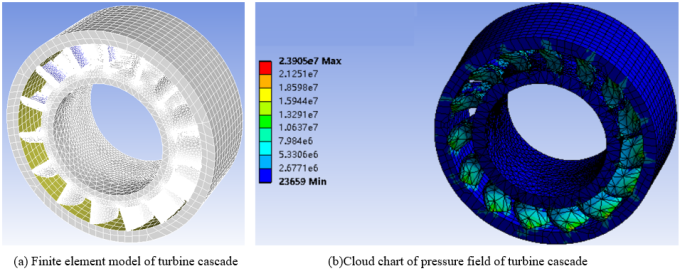
Meanwhile, based on the overall structural design of the turbine cascade completed on this platform, further finite element analysis and calculation were conducted (as shown in
Figure 7). The final calculation results indicated that the blade torque reached 18N·m, and the performance met the requirements of actual working conditions, thus completing the reliability verification analysis of the structural performance of the turbine drill guide vane cascade.
Figure 7. Calculation model and results of turbodrill blade cascade.
6. Conclusion
(1) The main factors affecting the performance of the turbine drill blade cascade are the blade inlet/outlet structural angles, the blade leading/trailing edge radii, the blade profile twist angle, the blade cascade pitch, and the blade cascade width. Through analysis of the blade cascade modeling parameters and in combination with the machining process, the actual operating conditions and dimensional parameters of the turbine are selected as the preconditions for the parametric design of the overall structure of the turbine drill blade cascade.
(2) Based on the one-dimensional flow theory of turbodrill design, by sorting out the transfer relationship between the structural dimensions and flow parameters of each key component in the overall structural design process of the turbodrill cascade, a hierarchical framework of overall design modules and sub-modules for the turbodrill cascade was established. A mathematical operation parameter relationship network diagram corresponding to the various parameters of the turbodrill cascade was formed, and the design modules in the overall design of the turbodrill cascade were programmed, making the entire turbodrill design and calculation process clear, efficient, and fast.
(3) Different from the existing traditional design methods for turbine cascade structures, this paper innovatively proposes a parametric design method for the overall structure of turbine cascades. Based on the modular design process, a design operation fitting system has been constructed, which utilizes program-driven computer-aided design software to complete 3D structural design. This system enables the design and generation of overall structural diagrams through program-driven computer-aided design software, providing flexibility in modifying various object parameters during the design process. It effectively addresses the issue of heavy design workload in the complex, diverse, and flexible design process of turbine cascade structures, with overall design efficiency improved by approximately 35% or more. This method has a strong guiding role in the development and design of turbodrills as well as in practical engineering applications.
Author Contributions
Yin Zhuo-cheng: Conceptualization, Formal Analysis, Investigation, Methodology, Resources, Visualization, Writing – original draft
Zhang Fuqiang: Conceptualization, Formal Analysis, Investigation
Liu Fei: Formal Analysis, Funding acquisition, Methodology
Gu Wenyu: Resources, Validation
Liu Qingren: Formal Analysis, Funding acquisition, Methodology
Funding
Funding support comes from fund projects: Jianghan Machinery Research Institute Limited Company project "Research and Development of Key Technical Equipment for Continuous Tubing Sidetracking" (Project No.: JJY202501).
Conflicts of Interest
The authors declare no conflicts of interest.
References
| [1] |
Lin Yuanhua, Zeng Dezhi, Li Runfang, Huang Wanzhi, Shi Taihe Research on New Blade Profile of Turbodrill and Its Computer Aided Design [J] Journal of Chongqing University (Natural Science Edition), 2004, 02: 24-27+39.
|
| [2] |
Calnan, D. (Cornerstone Natural Resources); Seale, R.; Beaton, T. Identifying applications for turbo-drilling and evaluating historical performances in North [C]. Journal of Canadian Petroleum Technology, v 46, n 6, p 34-39, June 2007 America.
|
| [3] |
Gong Pan, Wang Peng, Zhang Chen, Feng Ding, Tu Yiliu. Design and Research on Twisted Blade Shape of Turbodrill [J]. Machine Tool and Hydraulic, 2019, 47 (19): 153-158.
|
| [4] |
Computational procedure for optimum shape design based on chained Bezier surfaces parameterization [J]. Damir Vucina; Zeljan Lozina; Igor Pehnec. Engineering Applications of Artificial Intelligence, 2012.
|
| [5] |
Design of high-efficiency turbomachinery blades for energy conversion devices with the three-dimensional prescribed surface curvature distribution blade design (CIRCLE) method [J]. T. Korakianitis; I. A. Hamakhan; M. A. Rezaienia; A. P. S. Wheeler; E. J. Avital; J. J. R. Williams. Applied Energy, 2011(1).
|
| [6] |
Status and prospects of exploration and exploitation key technologies of the deep petroleum resources in onshore China [J]. Genshun Yao; Xianzhu Wu; Zandong Sun; Chunhao Yu; Yunhua Ge; Xianyou Yang; Long Wen; Chao Ni; Xiaodong Fu; Jianyong Zhang. Journal of Natural Gas Geoscience, 2018(1).
|
| [7] |
Computer-aided design of horizontal axis turbine blades [J]. F. Pérez-Arribas; I. Trejo-Vargas. Renewable Energy, 2012.
|
| [8] |
Feng Jin, Fu Daliang. New Method for Shape Design of Turbine Blades in Turbodrill Tools [J]. Petroleum Machinery, 2000 (11): 9-12+3.
|
| [9] |
Feng Chao, Xu Huajing, Huang Jian, Xia Chengyu, Liu Jian, Qian Liqin. Structural parameter optimization and fluid simulation of turbine hydraulic oscillator [J]. Science, Technology and Engineering, 2022, 22 (09): 3525-3531.
|
| [10] |
Jorge D. Camba, Manuel Contero. Pedro Company. Parametric CAD modeling: An analysis of strategies for design reusability [J]. Computer-Aided Design, v74, p18–31, May 2016.
|
| [11] |
Kubo, Masaaki; Ejiri, Eiji; Kumada, Haruo; Ishii, Yoshihiko. Improvement of prediction accuracy for torque converter performance: one-dimensional flow theory reflecting the stator blade geometry [J]. JSAE review, v 15, n 4, p 309-314, Oct 1994.
|
| [12] |
Lu, Xiu-Quan; Chu, Ya-Xu; Cai, Wei; Ma, Wen-Xing; Song, Jian-Jun. Predicting method for partial-filling performance of hydrodynamic retarder based on one-dimensional flow beam theory [J]. Jilin Daxue Xuebao (Gongxueban)/Journal of Jilin University (Engineering and Technology Edition), v 41, n 4, p 988-992, July 2011.
|
| [13] |
Sun Zhili, Ji Guangzhen, Yan Yutao, Yang Qiang. Parametric Design Technology for Mechanical Products [M]. Beijing: National Defense Industry Press, 2014, 01.
|
| [14] |
Javier Monedero, Zhang Tinghua. Parametric Design: Overview and Some Experience [J]. Urban Environmental Design, 2010, 10: 20-24.
|
| [15] |
Experimental study of circulation flow in a light dispersion hydrocyclone [J]. Yi Liu; Qiang Yang; Peng Qian; Hua-lin Wang. Separation and Purification Technology, 2014.
|
| [16] |
Fluid Flow Investigation through Small Turbodrill for Optimal Performance [J]. Amir Mokaramian; Vamegh Rasouli; Gary Cavanough. Mechanical engineering research, 2013.
|
| [17] |
Tribological behavior of PTFE nanocomposite films reinforced with carbon nanoparticles [J]. Jeong-Yeop Lee; Dong-Phill Lim; Dae-Soon Lim. Composites Part B, 2006.
|
| [18] |
Optimization design for turbodrill blades based on response surface method [J]. Xiaodong Zhang; Shimin Yu; Yan Gong; Yilan Li. Advances in Mechanical Engineering, 2016.
|
| [19] |
Computational procedure for optimum shape design based on chained Bezier surfaces parameterization [J]. Damir Vucina; Zeljan Lozina; Igor Pehnec. Engineering Applications of Artificial Intelligence, 2011(3).
|
| [20] |
Hydrodynamically detailed performance analysis of a mixed-flow waterjet pump using computational fluid dynamics [J]. Oh, H W; Yoon, E S. Proceedings of the Institution of Mechanical Engi, 2008(C9).
|
Cite This Article
-
APA Style
Zhuo-cheng, Y., Fuqiang, Z., Fei, L., Wenyu, G., Qingren, L. (2026). Research on Parameter Design Method for Downhole Turbodrill. American Journal of Mechanical and Industrial Engineering, 11(4), 93-103. https://doi.org/10.11648/j.ajmie.20261104.13
 Copy
|
Copy
|
 Download
ACS Style
Zhuo-cheng, Y.; Fuqiang, Z.; Fei, L.; Wenyu, G.; Qingren, L. Research on Parameter Design Method for Downhole Turbodrill. Am. J. Mech. Ind. Eng. 2026, 11(4), 93-103. doi: 10.11648/j.ajmie.20261104.13
Copy
|
Download
AMA Style
Zhuo-cheng Y, Fuqiang Z, Fei L, Wenyu G, Qingren L. Research on Parameter Design Method for Downhole Turbodrill. Am J Mech Ind Eng. 2026;11(4):93-103. doi: 10.11648/j.ajmie.20261104.13
Copy
|
Download
-
@article{10.11648/j.ajmie.20261104.13,
  author = {Yin Zhuo-cheng and Zhang Fuqiang and Liu Fei and Gu Wenyu and Liu Qingren},
  title = {Research on Parameter Design Method for Downhole Turbodrill},
  journal = {American Journal of Mechanical and Industrial Engineering},
  volume = {11},
  number = {4},
  pages = {93-103},
  doi = {10.11648/j.ajmie.20261104.13},
  url = {https://doi.org/10.11648/j.ajmie.20261104.13},
  eprint = {https://article.sciencepublishinggroup.com/pdf/10.11648.j.ajmie.20261104.13},
  abstract = {Turbodrill, as one of the extremely important downhole power operation tools in the field of oil and gas field exploration and development, has a wide range of application conditions and requirements. Among them, the blade grid of turbodrill, as the core component of turbodrill, directly affects the downhole operation performance of the drilling tool. However, the overall structural design of existing turbodrill tools requires the gradual derivation of blade geometry parameters based on theoretical formulas and repeated calibration. The overall design workload is large, the calculation steps are complex, and the overall design cycle is long. The existing traditional design methods have prominent problems. Therefore, in order to effectively improve the overall design efficiency and calculation accuracy of turbodrill, an innovative parametric design method for the overall structure of turbodrill blade cascade is proposed. Based on the theory of univariate flow and the modular parameterization design approach, a hierarchical framework for the overall design module and sub modules of the turbodrill blade cascade was established, and a parameter relationship network diagram was formed for the corresponding parameters in the design process of the stator and rotor of the guide vane cascade; And based on the modular design process, a parametric design and operation fitting system was built. At the same time, a program driven computer-aided design software was used to generate the overall three-dimensional structural diagram, and finally a parameterized design and operation platform for the overall structure of the turbine blade was obtained, which is easy to design and optimize. Based on the built design and operation platform, the overall structure design of the turbine blade was completed, and the feasibility of the design method and operation platform was verified using finite element calculation method. The research results show that the innovative parameterized design method and computing platform for the overall structure of turbine blade cascades effectively solve the problem of large design workload in the complex, diverse, and flexible design process of turbine blade cascades. The calculation accuracy has been improved by about 20%, and the overall design efficiency has been increased by more than 35%. The promotion and application of this innovative parameterized design method for the overall structure of turbine drilling tool blade cascades will greatly improve the design efficiency and calculation accuracy of downhole turbine drilling tool structures, which is of great significance for promoting the technological upgrading of China's intelligent manufacturing industry.},
 year = {2026}
}
Copy
|
Download
-
TY  - JOUR
T1  - Research on Parameter Design Method for Downhole Turbodrill
AU  - Yin Zhuo-cheng
AU  - Zhang Fuqiang
AU  - Liu Fei
AU  - Gu Wenyu
AU  - Liu Qingren
Y1  - 2026/08/24
PY  - 2026
N1  - https://doi.org/10.11648/j.ajmie.20261104.13
DO  - 10.11648/j.ajmie.20261104.13
T2  - American Journal of Mechanical and Industrial Engineering
JF  - American Journal of Mechanical and Industrial Engineering
JO  - American Journal of Mechanical and Industrial Engineering
SP  - 93
EP  - 103
PB  - Science Publishing Group
SN  - 2575-6060
UR  - https://doi.org/10.11648/j.ajmie.20261104.13
AB  - Turbodrill, as one of the extremely important downhole power operation tools in the field of oil and gas field exploration and development, has a wide range of application conditions and requirements. Among them, the blade grid of turbodrill, as the core component of turbodrill, directly affects the downhole operation performance of the drilling tool. However, the overall structural design of existing turbodrill tools requires the gradual derivation of blade geometry parameters based on theoretical formulas and repeated calibration. The overall design workload is large, the calculation steps are complex, and the overall design cycle is long. The existing traditional design methods have prominent problems. Therefore, in order to effectively improve the overall design efficiency and calculation accuracy of turbodrill, an innovative parametric design method for the overall structure of turbodrill blade cascade is proposed. Based on the theory of univariate flow and the modular parameterization design approach, a hierarchical framework for the overall design module and sub modules of the turbodrill blade cascade was established, and a parameter relationship network diagram was formed for the corresponding parameters in the design process of the stator and rotor of the guide vane cascade; And based on the modular design process, a parametric design and operation fitting system was built. At the same time, a program driven computer-aided design software was used to generate the overall three-dimensional structural diagram, and finally a parameterized design and operation platform for the overall structure of the turbine blade was obtained, which is easy to design and optimize. Based on the built design and operation platform, the overall structure design of the turbine blade was completed, and the feasibility of the design method and operation platform was verified using finite element calculation method. The research results show that the innovative parameterized design method and computing platform for the overall structure of turbine blade cascades effectively solve the problem of large design workload in the complex, diverse, and flexible design process of turbine blade cascades. The calculation accuracy has been improved by about 20%, and the overall design efficiency has been increased by more than 35%. The promotion and application of this innovative parameterized design method for the overall structure of turbine drilling tool blade cascades will greatly improve the design efficiency and calculation accuracy of downhole turbine drilling tool structures, which is of great significance for promoting the technological upgrading of China's intelligent manufacturing industry.
VL  - 11
IS  - 4
ER  -
Copy
|
Download





 Share This Article
 Twitter
 Linked In
 Facebook