Abstract
This paper presents hybrid position and force control (HPFC) methodology for position and as well as force tracking for upper limb rehabilitation of stroke patients. Stroke is a leading cause of disability in humans. Traditional rehabilitative therapies help regain motor function and ameliorate impairment, but they depend on the therapist’s experience and require many therapists, which is cost-prohibitive. Most robotic tasks with high severity such as rehabilitation, demands an effective force as well as position control scheme to ensure the safe physical contact between the robot and its environment in this case the patient. Some rehabilitation robots have been developed to help stroke survivors recover motor function. In past robots used for upper-limb rehabilitation employed general control schemes such as proportional integral derivative. To overcome the problem of force tracking in rehabilitation, robots require modern control techniques. To mimic the human upper-limb, and universality of application, an end-effector based robot is used for this study. To ensure the convergence of position and force errors to zero extensive simulations are performed. Two of assistant modes passive and active assistive rehabilitation are considered. Most common rehabilitation trajectories horizontal reaching, and vertical reaching are selected as robot’s motion for both passive and active assistive activities. The mathematical model of robots’ kinematics, dynamics, alongside the proposed control scheme has been discussed in detail.
Keywords
Hybrid Position and Force Control, Position Tracking, Force Tracking, Rehabilitation, Stroke
1. Introduction
The interruption of the flow of blood to the brain is known as stroke which results in disfigurement of brain cells and can be untreatable. Stroke is among the leading and common causes of permanent disability with symptoms such as spasticity and the leading cause of mortality today.
It is undoubtedly the subsequent driving reason for death on the planet and one of the significant reasons for procured inability in grown-ups
. Motor disfigurement on the upper limb and loss of hand agility are prime maladies that stroke tolerant have to suffer from, both of the above-mentioned dysfunctions are partially rectifiable by submitting to rehabilitation
. Not only stroke many people suffer injuries of the upper limb frequently at extremities level such as fingers and hands followed by a forearm. Impaired motor function or any form of disability leaves much stress on families and much more pressure on patients themselves. Due to lack of technology, awareness, and facilities in hospitals the percentage of stable patients with reduced upper extremity who obtain dexterity is dangerously low. Current well-being administrations are grappling to provide indefectible rehabilitation therapy to stroke victims. This has roused scientists to investigate the utilization of robots to give restoration treatment to stroke patients
| [3] | H. S. Lo and S. Q. Xie, “Medical Engineering & Physics Exoskeleton robots for upper-limb rehabilitation: State of the art and future prospects,” Med. Eng. Phys., vol. 34, no. 3, pp. 261–268, 2012, https://doi.org/10.1016/j.medengphy.2011.10.004 |
[3]
. To fully recover motor impairment and joint mobility patients are required to execute exercises. The conventional method that has been used for decades for the rehabilitation of post-stroke is physiotherapy. Due to limited financial and human resources, physiotherapy does not promote recovery on an optimal level. The therapist to patient ratio in underdeveloped countries such as Pakistan is insolvent.
In the last three decades, the examination on the improvement of recovery robots has been increased exponentially, chiefly for the neurorehabilitation of post-stroke patients. Recovery has been demonstrated to be effectual when it is both acute and including for the patient
, and robotics is one potential answer to impart intensity, by expanding the number of reiterations recommended by a specialist. The two significant highlights of the medicated exoskeletons are their capacities to apply forces alongside the assisted appendages and to give dependable joint estimations
. Over the last two decades, force tracking remains the main concern of the researchers. Initially, the two major force control paradigms also known as classical force control schemes that have been proposed are 1) Hybrid force and position control
| [5] | J. J. Craig, “Hybrid Position / Force Control of,” J. Dyn. Syst. Meas. Control, vol. 102, no. June 1981, pp. 126–133, 1981. |
[5]
and 2) Impedance control
| [6] | N. Hogan, “Impedance Control: An Approach to Manipulation: Part II — Implementation,” no. June 1983, 1985. |
| [19] | N. Hogan, “Wp2 4: 00,” pp. 304–313. |
[6, 19]
.
To address the joint mobility of upper extremity compound movement, rehabilitation robots are required to work on more than one DoF. Upper limb remediation robots can be halved into two major groups, exoskeleton, and end-effector-based. One of the earliest robots developed for upper limb rehabilitation is MIT-Manus which construct with a SCARA configuration and provides two translational DoF to advance the ante brachium and forearm
. Extensive clinical testing of the MIT-Manus and the In-Motion ARM robot affirmed the enhancement of the motor range of the weakened arm after robotic treatment
| [8] | B. T. Volpe, H. I. Krebs, N. Hogan, L. Edelsteinn, C. M. Diels, and M. L. Aisen, “Robot training enhanced motor outcome in patients with stroke maintained over 3 years,” Neurology, vol. 53, no. 8, pp. 1874 LP – 1874, Nov. 1999, https://doi.org/10.1212/WNL.53.8.1874 |
[8]
. In the second half of the most recent decade, various upper appendage restoration robots have been created. The first commercially available robot for upper limb rehabilitation came in 2011
| [9] | R. Riener, U. Keller, A. Duschau-Wicke, V. Klamroth-Marganska, and T. Nef, “Transferring ARMin to the Clinics and Industry,” Top. Spinal Cord Inj. Rehabil., vol. 17, pp. 54–59, May 2011, https://doi.org/10.1310/sci1701-54 |
[9]
.
The multiple degrees of freedom allow the robot to interact with the whole limb by applying distributed force. In the last decade, numerous rehabilitation robots have been made that use different control schemes. Two degrees of freedom (DoF) upper limb exoskeletal robot have been designed and produced which accompanies a proportional integral derivative (PID) controller for position control
| [10] | A. Yavuz, M. E. Aktan, and A. T. Koru, “DESIGN, PRODUCE AND CONTROL OF A 2-DOF UPPER LIMB EXOSKELETAL ROBOT,” vol. 5, no. 2, pp. 119–130, 2019. |
[10]
. A five DoF exoskeleton has been made which comprises impedance control to give the stroke victim the likelihood to effectively regulate the assignment and being passively steered by the robot when the victim is unable to complete that task
| [11] | A. Frisoli, F. Salsedo, M. Bergamasco, B. Rossi, and M. C. Carboncini, “A force-feedback exoskeleton for upper-limb rehabilitation in virtual reality,” Appl. Bionics Biomech., vol. 6, no. 2, pp. 115–126, 2009, https://doi.org/10.1080/11762320902959250 |
[11]
. The local PID feedback controller along with impedance control is used to minimize the position error and force error between the human limb and robot
| [12] | B. C. Tsai, W. W. Wang, L. C. Hsu, L. C. Fu, and J. S. Lai, “An articulated rehabilitation robot for upper limb physiotherapy and training,” in IEEE/RSJ 2010 International Conference on Intelligent Robots and Systems, IROS 2010 - Conference Proceedings, 2010, pp. 1470–1475. https://doi.org/10.1109/IROS.2010.5649567 |
[12]
. A visuo-vibrotactile feedback method is used on a planar robot for upper extremities rehabilitation
| [13] | G. Salas-lópez, O. Sandoval-gonzález, and I. Herrera-aguilar, “Design and development of a planar robot for upper extremities rehabilitation with visuo-vibrotactile feedback,” vol. 3, pp. 147–156, 2012, https://doi.org/10.1016/j.protcy.2012.03.016 |
[13]
. Artificial Neural Network (ANN) technique is used to directly predict the position angle for a three DoF underactuated robot arm to minimize the need for system modeling thus controller
| [14] | M. A. Fikri, S. C. Abdullah, and M. H. M. Ramli, “Arm exoskeleton for rehabilitation following stroke by learning algorithm prediction,” Procedia - Procedia Comput. Sci., vol. 42, pp. 357–364, 2014, https://doi.org/10.1016/j.procs.2014.11.074 |
[14]
. For rehabilitation of elbow joint using resistance training a customized impedance and admittance control scheme is proposed that detects the motion of the human arm instead of the robot
| [15] | Z. Song et al., “Implementation of resistance training using an upper-limb exoskeleton rehabilitation device for elbow joint,” J. Med. Biol. Eng., vol. 34, no. 2, pp. 188–196, 2014, https://doi.org/10.5405/jmbe.1337 |
[15]
.
The force tracking error is unavoidable in all of the above methods. One of the basic ways to control the robot is to inactively control the movement along an ideal reference path using excessive gains. PID is a feedback control scheme similar to passive control, which governs position or force with respect to a known reference. Both of the above, mentioned methods are found to be useful only at the early stages of rehabilitation. A force control scheme that has the position signal as feedback is known as Impedance Control. While admittance control is opposite of impedance control where the position is being controlled while the feedback signal is in the form of force
| [16] | T. Proietti, V. Crocher, A. Roby-Brami, and N. Jarrasse, “Upper-limb robotic exoskeletons for neurorehabilitation: A review on control strategies,” IEEE Rev. Biomed. Eng., vol. 9, pp. 4–14, 2016, https://doi.org/10.1109/RBME.2016.2552201 |
[16]
. Both are indirect force control methods. ANN technique opts for no force control because it is based on prediction and estimation of the control parameters as well as there is no dynamic relationship exist betwixt the human appendage and robot’s end-effector. The learning methods are not suitable for force tracking problems because these methods require a lot of data for training the system.
A lot of work has been done in designing the rehabilitation robot considering mechanical features such as inertia, friction, back drivability, etc. The key characteristics of rehabilitation robots lie in their control strategy as well. Only position control or force control strategy is not adequate for accurate implementation of upper limb rehabilitation, because the desired force should be preserved while traversing the prescribed path. To turn up the above drawbacks, the hybrid position and force control technique is developed
| [5] | J. J. Craig, “Hybrid Position / Force Control of,” J. Dyn. Syst. Meas. Control, vol. 102, no. June 1981, pp. 126–133, 1981. |
[5]
and implemented
, which states that for a given surface the end effector should be force controlled in the perpendicular orientation to the surface and position-controlled in the normal order to the surface.
Assistive mode provides rehabilitation in three forms known as passive, triggered passive, and partially/active assistive. The drawback of the passive technique is that it is only useful at the preliminary juncture of post-stroke healing. In this technique, we are only controlling the motion of the robot concerning a fixed reference path via position feedback control such as proportional-integral- derivative feedback (PID). In passive control, the reference trajectory is created by recording the physiotherapist’s inputs on a distorted limb which is a tiring process that can also contain human errors. In triggered passive control, the patient decides to trigger the assistance of a robot. As the patient is not participating in passive control and triggered passive control and all work is done by robots, their effectiveness for rehabilitation becomes questionable.
Assistance is found to be very encouraging in early patients as it introduces motivation as it allows the patient to actively control the motion. One of the decisive attributes for the meditated robot is to permit mutual control as soon as the stroke victim has recuperated least motor scope and articular surface mobility. This compliance between robot and patient cannot be achieved by using rigid controllers of high corrective gains. Instead of rigid controllers, modern rehabilitation robots rely on flexible control schemes such as Impedance control and HPFC.
Impedance control is an indirect force control strategy with position feedback. Apart from being an indirect force control scheme, impedance control is only coherent for lightweight rehabilitation robots. In rehabilitation robots, complications make an appearance where it is imperative to recoup for gravity and friction. On the contrary, the hybrid force, and position control scheme gives the vantage of including friction and gravity compensation. Upper limb rehabilitation demands that a driving force must be applied in a lengthwise direction concerning the covet track which guides the victim towards the precise implementation of the prescribed movement and a constraint force must be applied in a cross-over way to the motion to minimize errors. The HPFC scheme gives the freedom to independently control force and position simultaneously.
The rest of the paper is arranged as follows. Robot modeling that includes kinematics and dynamics are discussed in section 2. In section 3, robot control scheme and proposed approach is explained. Rehabilitation, and its types are discussed in section 4. Robot patient interaction is discussed in section 5. Simulations and results are presented in section 6 followed by conclusion in section 7.
2. Robot Modeling
In this chapter, we derived and explained the robot kinematics as well as robot dynamics formulation for the end effector-based robot used for rehabilitation. The kinematics of the robot describes the motion of the robot without considering the causes of the motion. When we are observing the kinematics of the robot, the torques and forces that cause the manipulanda proceed is not considered. On the other hand, the robot dynamics correlates the joint accelerations and joint torques.
2.1. Kinematics
The position kinematics can be subdivided into two categories, i) Forward Kinematics, ii) Inverse Kinematics.
2.1.1. Forward Kinematics
In the forward kinematics we have information about joint angles. And using joint angles we calculate end-effector location and orientation. While on the other hand in inverse kinematics the location of end-effector is known. We calculate joint angles based on the location of manipulanda.
In robotic applications, the DH-convention is utilized for frame allocation
| [18] | J. Wiley, “Robot Modeling and Control”. |
[18]
. The other method to calculate the forward kinematics is homogenous transformation. Using DH-convention, each link in the robot manipulator is assigned to a coordinate frame.
The homogeneous transformation of ith joint w.r.t (i − 1)th joint is mathematically represented as
(1)
(3)
Where , , , and indicates cos(), sin(), sin(), and cos() respectively. While and describes the rotation and translation of the i-1 joint w.r.t i joint.
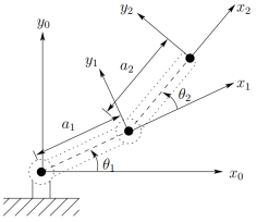
Forward kinematics of 2R planar robot using D-H convention is mathematically represented as,
(4)
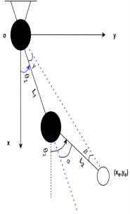
The frame of reference on each joint is represented as shown in
figure 1. The DH parameters are presented in
Table 1.
Table 1. DH parameters of 2 DoF Robot.
Link | Link Length | Alpha | Offeset | Theta |
1 | L1 | 0 | 0 | |
2 | L2 | 0 | 0 | |
Below are the forward position kinematics equations for the 2R planar robot used for rehabilitation.
2.1.2. Inverse Kinematics
In inverse kinematics we used end-effector position to compute the joint angles. There are two approaches to derive the inverse kinematics, one is geometric, and other is algebraic. From the
figure 1, applying Pythagoras theorem for joint angle θ
2 gives.
Figure 1. Frame of reference on each joint of 2-DoF end-effector robot based on Denavit-Hartenberg convention.
(8)
(9)
Where,
(10)
As
Solving for
(12)
Using the forward kinematics equations (
5), (
6), and (
7), the correlation between the joint space and task space variables is expressed as
The derivative of (
13) w.r.t time gives,
Where J describes the Jacobian matrix that establishes the relationship between joint velocities with the task-space velocities.
2.2. Robot Dynamics
The robot dynamics illustrates the relationship between the forces and motions. Given the joint torques, the joint accelerations computed by forward dynamics. On the other hand, inverse dynamics provides joint torques for given joint accelerations.
The two major approaches to develop the dynamics equations are Newton-Euler formulation, and Euler-Lagrange formulation. Newton-Euler method construct dynamic equations from forces and torques existing between each link in the manipulator. Whereas, Euler-Lagrange approach develop dynamic equations by examining the difference between Kinetic energy and Potential energy.
Using Euler-Lagrange formulation, the following dynamic equation of motion can be utilized to present the dynamic model of an n-link robot manipulator in the standard way.
(15)
where,
: Joint position, velocity, and acceleration
: Joint coordinate vector, n is number of joints
D, H(q): Positive-definite inertia matrix
g(q): Gravitational force
: Frictional forces
: Coriolis and centrifugal terms
τ: Joint torques
Equation of motion for the 2R planar robot in task space can be represented as
(16)
where,
(18)
(21)
(25)
(26)
(28)
(29)
(31)
3. Robot Control
HPFC scheme is first proposed by J. Craig in 1981. As the impedance controller relies on the manipulator and external force being coupled together, in contrast in the HPFC scheme, the manipulator and end-effector force are not coupled together
| [21] | Bilal, Muhammad & Akram, Muhammad & Rizwan, Mohsin. (2022). Adaptive Variable Impedance Control for Multi-axis Force Tracking in Uncertain Environment Stiffness with Redundancy Exploitation. Control Engineering and Applied Informatics. 24. 35-45. |
| [22] | Bilal, Muhammad. (2020). Implementation of Adaptive Variable Impedance Control for Dynamic Force Tracking on Redundant Manipulator. https://doi.org/10.13140/RG.2.2.32803.73767 |
[21, 22]
.
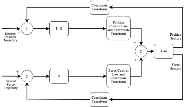
HPFC scheme is proposed so that both the position and force of the robot can be controlled simultaneously. Robotic tasks such as rehabilitation requires the robot to act in accordance with the environment, respond to the force applied on the end effector, and adapt to the position unpredictability of the environment. The architectural layout of the hybrid control is shown above in
Figure 2.
Figure 2. Architecture Block Diagram of HPFC.
The elementary concept behind the formation of HPFC scheme lies in the task planning. Any desired task can be described with a set of constraints. With every key element of robotic task, a set of restriction are associated known as natural constraints. Natural constraints are formed due to the geometric limitations of the task. Artificial constraints come due to the desired behavior such as motion or force forms in task configuration.
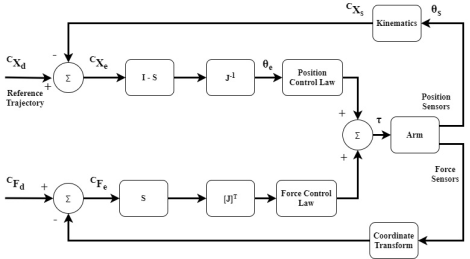
Figure 3. Conceptual Block Diagram of HPFC.
Be mindful that the coordinate system that is used to specify constraints and trajectories does not necessarily correspond to the manipulator's joints or its end effector. Instead, the coordinates are selected in line with the task geometry. The conceptual diagram of the hybrid position and force controller is represented as shown in the
Figure 3 above.
where,
: Desired position (motion)
: Position error
: Desired force
: Force error
: Selection matrix
: Jacobian
: Sensed (actual) position
: Joint angle error
: Sensed (actual) joint angle
: Computed Torque
The above figure indicates that there are two control loops present int the hybrid control. The upper loop is of position control, and the lower loop is for force control. The force control will not be responsible for controlling the position of the robot. It will only make sure that the desired force is applied. Likewise, the position control will only be responsible for controlling the position parameter only. The position controller consider that the arm of the robot is in free space and no force is acting on it. The inverse jacobian is used to transform the position error from cartesian frame to joint error.
The basic premise of our minimal level hybrid controller is that each joint's actuator driving signal should represent that joint's instantaneous contribution to the fulfillment of the positional and force constraints.
The actuator driving signal can be expressed as,
(33)
where,
: Torque applies by the ith actuator
: Force compensator jth input and ith output
: Position compensator jth input and ith output
: Force error in jth DoF
: Position error in jth DoF
: Component of compliance selection vector
DoF under position control
DoF under force control
The compliance selection vector S is a binary m-tuple. It distinguishes between the DoF under position control to the DoF under force control. The coordinate and kinematics blocks in the diagram indicate that the sensed position and force signal must be transformed into cartesian frame C attached with the task. That is implemented using the following equations,
Where, {H} represents the hand frame, and {C} represents the Cartesian frame. For a given task the robot’s end effector should be position controlled normal to the surface, force controlled perpendicular to the surface. And the necessary criteria in order to implement is that there should be no friction present between the manipulators end effector and the task geometry or surface.
In the conceptual hybrid controller, besides error correction algorithms it is sensed that the ideal HPFC should include feed forward compensation for gravity, and robot dynamics.
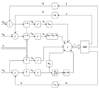
To accomplish that hybrid control scheme is proposed in terms of joint space. The only assumption taken here is that the position of the task where a desired force is required to apply is known to a certain level, or there is an error margin available in the position of robot. This eliminates the transformation of position signal from Cartesian space to joint space, as well as force error signal. The proposed HPFC scheme is expressed as in
Figure 4.
Figure 4. Hybrid Position and Force Control.
Where,
: Inertia
G(q): Gravity Compensation
: Proportional gain for force controller
: Proportional gain for position controller
: Derivative gain for position controller
: Desired joint acceleration
The mathematical form of the joint space HPFC can be expressed as,
(38)
Where,
: Torque computed for force control
: Torque computed for position control
: Gravity compensation
In terms of Cartesian space the hybrid controller with feed forward compensation that can also control the position and force independently is shown in the equations below. One of the major differences is that now the position control is comprised of two parts, position, and velocity. The control laws for the hybrid controller are expressed as
(39)
(40)
Due to friction, and decay of damping with the speed, a non-linearity occurs. To overcome this non-linearity, the integral gain is used in the force control loop. To bound the integral gain values for non-linearity a saturation block is used.
4. Rehabilitation
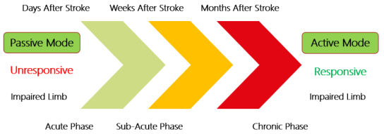
The term rehabilitation indicates the process of restoring someone back to health or a regular life via training and therapy following incarceration, addiction, or disease. Neurorehabilitation is method for people who have any disorder in the nervous system, or faced injury. A general neurorehabilitation timeline for stroke patients is shown in
Figure 5.
Figure 5. Neurorehabilitation Timeline.
Based on the time, the phases of rehabilitation can be divided into three categories known as acute phase, sub-acute phase, and chronic phase. From the time of occurrence to the first seven days, is called as acute phase. After the first week to the six months post stroke period is called as sub-acute phase. And after six months, it is called as chronic phase.
The type of neurorehabilitation strategy adapted for survivor is greatly dependent on the phase. In acute phase the limb is unresponsive, and it can hardly apply any force on the rehabilitative device. In sub-acute phase the limb is somewhat responsive and can apply minute force on the rehabilitation equipment. In the chronic phase the limb is responsive, and it can apply a considerable amount of force on the rehabilitative manipulator.
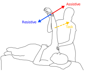
Globally the upper-limb robotic rehabilitation strategies for stroke patient are categorized into three domains i) Assistance, ii) Correction and iii) Resistance. The
Figure 6 shows the neurorehabilitation strategies.
Figure 6. Global Strategies for Neurorehabilitation.
4.1. Assistance Mode
In assistance mode, the robot is assisting the patient by supporting the weight of the limb and by providing the forces to complete the task prescribed by the physiotherapist.
There are three strategies in assistive mode of rehabilitation named as passive control, triggered passive control, and partially assistive control.
4.1.1. Passive Control
One of the fundamental methods of controlling a manipulator is to control its motion against desired path through position feedback. In rehabilitation, the passive control is opted for early stages of post stroke therapy. Because in this phase the limb is totally unresponsive, so only the movement of the impaired limb through a prescribes path is considered. The major goal behind the passive control is that by exposing the impaired limb to the intensive iterative motion, the movement may be identified by the brain.
4.1.2. Triggered Passive Control
In this strategy, user selects when to activate the assistance of the robot. This technique is used where patient is interacting with the rehabilitation device using brain-machine interface.
4.1.3. Partially Assistive / Active Assistive Control
The major drawback of the passive control is that the patient is not actively contributing to the activity, because patient is not applying any force to perform the task. This reduces the required stimulation to affected muscles, and joints. As soon as patient recovered to a level where he can apply minimal force, the robot should allow the shared control. This scheme is known as active assistive control. Not only the shared coordination, the muscle strength can also be improved using this methodology.
4.2. Correction Mode
In correction mode, the robot is only providing the assistance when the patient is not performing the task accurately. On detection of deviation from the goal, the robot will force the injured limb towards the task.
4.3. Resistance Mode
In resistance mode, the robot works against the movements of the patient in order to increase the error. This will make the task difficult to achieve, and it will train the patient to adapt to unknown, and complex perturbations.
5. Robot Patient Interaction
One of the major goals of robotic-based rehabilitation is that robots are reprogrammable and multifunctional. These two attributes of robot allow it be used in different phases (acute, sub-acute, chronic) of rehabilitation. Also, for a particular patient a combination of different strategies (passive, active assistive) etc. found to be more effective in regaining the motor mobility.
5.1. Exoskeleton vs End-Effector Based Robot
There are two types of robotic devices used for upper limb rehabilitation, named as exoskeletons, and end-effector based robots. In terms of cost analysis, the exoskeletons are more expensive than the end-effector based robots.
One other major advantage the end-effector robots have over the exoskeleton is universality. As same end-effector based manipulator can be used for different patients, or for one patient in different phases without the need to modify hardware or software. On the other hand, a big advantage of exoskeleton robots is that, they can target the particular joint, or muscle of the patient as they apply distributed forces along the limb. Even though the exoskeleton robots are multi-contact systems, most of the rehabilitation robots are developed using end-effector manipulanda. In end-effector based manipulator, there is a single interaction point between the patient and the robot close to wrist but it provides motor training to the whole limb.
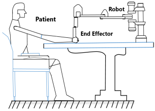
Figure 7. Robot Patient Interaction.
In this study we have taken the end-effector based approach as expressed in
Figure 7. Two linkages that resemble the human upper arm and forearm shown in
Figure 8 are part of the robot's design to mimic the human body (
Figure 9).
Figure 8. End Effector Robot Model.
Figure 9. Posterior View of Human Upper Limb.
5.2. Patient Force
Depending on the patient's state, the nature of their deterioration, and the particular task or activity, the average force that a stroke victim applies might vary substantially. Following are some of the prominent aspects that contributes to the different forces. Severity of the stroke: (Mild/ moderate/ severe), Location of the stroke: (Cortical/ subcortical/ brainstem), Stage of recovery: (Acute/ subacute/ chronic), Type of movement (Grip/ arm extension/ shoulder flexion, etc.), and Individual's pre-stroke strength and function. Nonetheless, certain research offers valuable perspectives on stroke victims' ability to generate force:
A study on grip strength found that stroke patients had an average grip strength of around 10-20 N (Newtons) compared to 30-40 N for healthy individuals
| [23] | S. S Kim et al, (2017) Grip strength and hand function in patients with stroke. |
[23]
. According to a different study on arm motions, stroke patients' average forces during reaching and grasping activities ranged from 2 to 10 N
| [24] | J. H. Cauraugh et al., (2005) Forces and moments generated by patients with stroke during reaching and grasping. |
[24]
.
5.3. Rehabilitation Trajectory
To encourage an adequate recovery, a planar robot intended for upper limb rehabilitation following a stroke ought to incorporate a range of training sessions incorporating various movement patterns. Horizontal reach
| [26] | Direction-dependent differences in the quality and quantity of horizontal reaching in people after stroke, Shintaro Uehara, Akiko Yuasa, Kazuki Ushizawa, Shin Kitamura, Kotaro Yamazaki, Eri Otaka, and Yohei Otaka, Journal of Neurophysiology 2023 130: 4, 861-870. |
[26]
, vertical reach, diagonal path, circular motion, and figure of eight are the most commonly implemented rehabilitative trajectories in rehabilitation manipulators. The first two horizontal and vertical reach are used as a robots’ prescribed path in this study and control parameters are fine-tuned accordingly.
Because the muscles utilized during each exercise vary, so do the effects of each approach on the patient. Horizontal reach found to improve shoulder flexion and abduction, as well as elbow and wrist movements.
While elbow extension also gets superior in the case of vertical reach in addition to shoulder abduction and flexion.
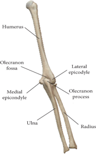
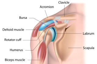
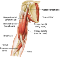
Deltoid, and rotator cuff muscles (
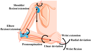
Figure 10) are responsible for shoulder abduction and flexion, and stabilization. Biceps brachii and triceps brachii shown in (
Figure 11) are responsible for flexion and extension movements (
Figure 12) respectively
| [25] | Amador LDF, Castillo Castañeda E, Laribi MA, Carbone G. Design and Analysis of VARONE a Novel Passive Upper-Limb Exercising Device. Robotics. 2024; 13(2): 29. https://doi.org/10.3390/robotics13020029 |
[25]
. Brachioradialis of forearm, flexor and extensor of wrist and hand, and intrinsic hand muscles are common muscles that are triggered and actuated in both reaches.
Figure 10. Shoulder Muscles for Abduction, Adduction.
Figure 11. Elbow Joints Muscles for Flexion and Extension
Figure 12. Human Upper-Limb Joints Motions.
6. Simulations and Results
The proposed control scheme is implemented on the 2R planar robot to perform the passive, and active assistive upper limb rehabilitation. The real-world circumstances have been implemented into simulations to successfully validate the suggested strategy.
MATLAB and SIMULINK are used for performing a number of simulations based on rehabilitation applications. The full-arm dynamics have been incorporated within the simulations to examine real-time behavior. The robot’s model parameters are m1 = 2 kg, m2 = 0.850 kg, and links length are L1 = 35 cm, and L2 = 31 cm. The PID controller gain parameters are tuned using the SQP algorithm.
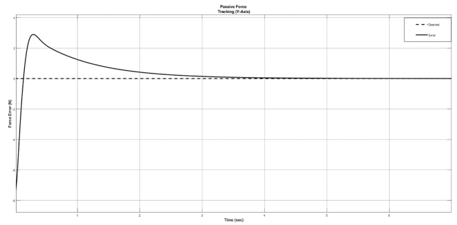
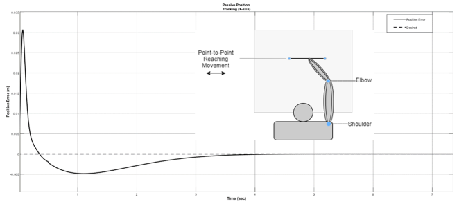
In passive rehabilitation, performance of the proposed control scheme is evaluated by observing the force (
Figure 13) and position tracking errors (
Figure 14). As we know, in passive rehabilitation the impaired limb is totally unresponsive. So, the stiffness observed by the robot is close to zero.
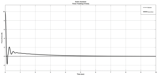
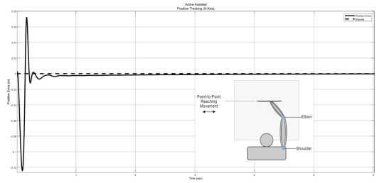
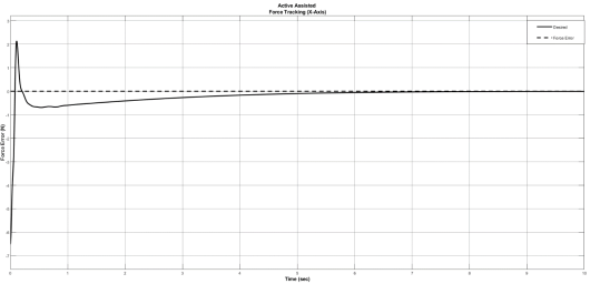
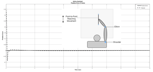
In active assistive rehabilitation, execution of the proposed control scheme is evaluated by observing the force and position tracking errors in both axes. Firstly, the position is controlled in x-axis, and force is controlled in y-axis. Then the position is controlled in y-axis while the force is being controlled in the x-axis. In active assisted rehabilitation the impaired limb is a bit responsive. So, the stiffness observed by the robot is taken as,
For the force tracking in y-axis, and position in x-axis the steady state error is shown in
Figure 15,
Figure 16 respectively. Conversely, for the force tracking in x-axis, and position in y-axis the steady state error is shown in
Figure 17, and
Figure 18.
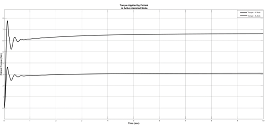
For the desired force, the torque applied by the patient on the end effector of the manipulator is shown in
Figure 19.
Figure 13. Passive Force Tracking in Y-axis.
Figure 14. Passive Position Tracking in X-axis.
Figure 15. Active Assisted Force Tracking in Y-axis.
Figure 16. Active Assisted Position Tracking in X-axis.
Figure 17. Active Assisted Force Tracking in X-axis.
Figure 18. Active Assisted Position Tracking in Y-axis.
Figure 19. Torque Applied by Patient in Active Assistive Mode.
All the position, and force tracking graphs of active assisted rehabilitation indicates that both the position and force errors are converges to zero.
7. Discussion and Conclusions
In this study, HPFC scheme with optimized controller parameters is proposed to constructively deal with the force as well as position tracking problem. The proposed control structure traversed the desired trajectory while maintaining the desired force with the subject. In order to validate the proposed control scheme, two cases are considered: passive and active assistive rehabilitation. The proposed approach effectively resolved the force and position tracking problem in both cases of rehabilitation reasonably well. In addition, the proposed approach is able for time varying force tracking as well. The complete mathematical model of kinematics and full arm dynamics are presented herein along with the complete derivation of the proposed control scheme. Perhaps more crucial than its capacity to carefully monitor changes in reference input is the system's capacity to exert a consistent force on a moving environment. For multi degree of freedom position trajectories such as circle, the proposed approach will be tested on 3 DOF articulated robotic manipulator.
Abbreviations
HPFC | Hybrid Position and Force Control |
DoF | Degrees of Freedom |
DH | Denavit Hartenberg |
PID | Proportional Integral Derivative |
ANN | Artificial Neural Network |
Acknowledgments
I would like to thank Human-Centered Robotics Lab team, and Principal Investigator Dr. Ali Raza for his support and guidance.
Author Contributions
Muhammad Ali: Conceptualization, Data Curation, Investigation, Methodology, Formal Analysis, writing – original draft, Resources
Muhammad Bilal: Data curation, Methodology, Investigation
Muhammad Nadeem Akram: Project Administration, Resources, Visualization
Mohsin Rizwan: Validation, Supervision, Visualization, Review
Funding
This work is not supported by any external funding.
Data Availability Statement
Not applicable.
Conflicts of Interest
The authors declare no conflicts of interest.
References
| [1] |
V. S. Huang and J. W. Krakauer, “Robotic neurorehabilitation: a computational motor learning perspective,” vol. 13, pp. 1–13, 2009,
https://doi.org/10.1186/1743-0003-6-5
|
| [2] |
C. L. Richards, F. Malouin, and S. Nadeau, Stroke rehabilitation: clinical picture, assessment, and therapeutic challenge, 1st ed., vol. 218. Elsevier B. V., 2015.
https://doi.org/10.1016/bs.pbr.2015.01.003
|
| [3] |
H. S. Lo and S. Q. Xie, “Medical Engineering & Physics Exoskeleton robots for upper-limb rehabilitation: State of the art and future prospects,” Med. Eng. Phys., vol. 34, no. 3, pp. 261–268, 2012,
https://doi.org/10.1016/j.medengphy.2011.10.004
|
| [4] |
M. Lotze, C. Braun, N. Birbaumer, S. Anders, and L. G. Cohen, “Motor learning elicited by voluntary drive,” pp. 866–872, 2003,
https://doi.org/10.1093/brain/awg079
|
| [5] |
J. J. Craig, “Hybrid Position / Force Control of,” J. Dyn. Syst. Meas. Control, vol. 102, no. June 1981, pp. 126–133, 1981.
|
| [6] |
N. Hogan, “Impedance Control: An Approach to Manipulation: Part II — Implementation,” no. June 1983, 1985.
|
| [7] |
H. I. Krebs et al., “Rehabilitation robotics: pilot trial of a spatial extension for,” vol. 15, pp. 1–15, 2004,
https://doi.org/10.1186/1743-0003-1-5
|
| [8] |
B. T. Volpe, H. I. Krebs, N. Hogan, L. Edelsteinn, C. M. Diels, and M. L. Aisen, “Robot training enhanced motor outcome in patients with stroke maintained over 3 years,” Neurology, vol. 53, no. 8, pp. 1874 LP – 1874, Nov. 1999,
https://doi.org/10.1212/WNL.53.8.1874
|
| [9] |
R. Riener, U. Keller, A. Duschau-Wicke, V. Klamroth-Marganska, and T. Nef, “Transferring ARMin to the Clinics and Industry,” Top. Spinal Cord Inj. Rehabil., vol. 17, pp. 54–59, May 2011,
https://doi.org/10.1310/sci1701-54
|
| [10] |
A. Yavuz, M. E. Aktan, and A. T. Koru, “DESIGN, PRODUCE AND CONTROL OF A 2-DOF UPPER LIMB EXOSKELETAL ROBOT,” vol. 5, no. 2, pp. 119–130, 2019.
|
| [11] |
A. Frisoli, F. Salsedo, M. Bergamasco, B. Rossi, and M. C. Carboncini, “A force-feedback exoskeleton for upper-limb rehabilitation in virtual reality,” Appl. Bionics Biomech., vol. 6, no. 2, pp. 115–126, 2009,
https://doi.org/10.1080/11762320902959250
|
| [12] |
B. C. Tsai, W. W. Wang, L. C. Hsu, L. C. Fu, and J. S. Lai, “An articulated rehabilitation robot for upper limb physiotherapy and training,” in IEEE/RSJ 2010 International Conference on Intelligent Robots and Systems, IROS 2010 - Conference Proceedings, 2010, pp. 1470–1475.
https://doi.org/10.1109/IROS.2010.5649567
|
| [13] |
G. Salas-lópez, O. Sandoval-gonzález, and I. Herrera-aguilar, “Design and development of a planar robot for upper extremities rehabilitation with visuo-vibrotactile feedback,” vol. 3, pp. 147–156, 2012,
https://doi.org/10.1016/j.protcy.2012.03.016
|
| [14] |
M. A. Fikri, S. C. Abdullah, and M. H. M. Ramli, “Arm exoskeleton for rehabilitation following stroke by learning algorithm prediction,” Procedia - Procedia Comput. Sci., vol. 42, pp. 357–364, 2014,
https://doi.org/10.1016/j.procs.2014.11.074
|
| [15] |
Z. Song et al., “Implementation of resistance training using an upper-limb exoskeleton rehabilitation device for elbow joint,” J. Med. Biol. Eng., vol. 34, no. 2, pp. 188–196, 2014,
https://doi.org/10.5405/jmbe.1337
|
| [16] |
T. Proietti, V. Crocher, A. Roby-Brami, and N. Jarrasse, “Upper-limb robotic exoskeletons for neurorehabilitation: A review on control strategies,” IEEE Rev. Biomed. Eng., vol. 9, pp. 4–14, 2016,
https://doi.org/10.1109/RBME.2016.2552201
|
| [17] |
G. N. S. D. L. Wedel, “AN EXPERIMENT IN HYBRID POSITION/FORCE CONTROL OF A SIX DOF REVOLUTE MANIPULATOR,”1988,
https://doi.org/10.1109/ROBOT.1988.12301
|
| [18] |
J. Wiley, “Robot Modeling and Control”.
|
| [19] |
N. Hogan, “Wp2 4: 00,” pp. 304–313.
|
| [20] |
A. A. Maciejewski and C. A. Klein, “Obstacle Avoidance for Kinematically Redundant Manipulators in Dynamically Varying Environments,” Int. J. Rob. Res., vol. 4, no. 3, pp. 109–117, Sep. 1985,
https://doi.org/10.1177/027836498500400308
|
| [21] |
Bilal, Muhammad & Akram, Muhammad & Rizwan, Mohsin. (2022). Adaptive Variable Impedance Control for Multi-axis Force Tracking in Uncertain Environment Stiffness with Redundancy Exploitation. Control Engineering and Applied Informatics. 24. 35-45.
|
| [22] |
Bilal, Muhammad. (2020). Implementation of Adaptive Variable Impedance Control for Dynamic Force Tracking on Redundant Manipulator.
https://doi.org/10.13140/RG.2.2.32803.73767
|
| [23] |
S. S Kim et al, (2017) Grip strength and hand function in patients with stroke.
|
| [24] |
J. H. Cauraugh et al., (2005) Forces and moments generated by patients with stroke during reaching and grasping.
|
| [25] |
Amador LDF, Castillo Castañeda E, Laribi MA, Carbone G. Design and Analysis of VARONE a Novel Passive Upper-Limb Exercising Device. Robotics. 2024; 13(2): 29.
https://doi.org/10.3390/robotics13020029
|
| [26] |
Direction-dependent differences in the quality and quantity of horizontal reaching in people after stroke, Shintaro Uehara, Akiko Yuasa, Kazuki Ushizawa, Shin Kitamura, Kotaro Yamazaki, Eri Otaka, and Yohei Otaka, Journal of Neurophysiology 2023 130: 4, 861-870.
|
Cite This Article
-
ACS Style
Ali, M.; Bilal, M.; Akram, M. N.; Rizwan, M. Hybrid Position and Force Control for Upper Limb Rehabilitation of Stroke Patient. Am. J. Mech. Ind. Eng. 2024, 9(2), 28-42. doi: 10.11648/j.ajmie.20240902.12
 Copy
|
Copy
|
 Download
-
@article{10.11648/j.ajmie.20240902.12,
  author = {Muhammad Ali and Muhammad Bilal and Muhammad Nadeem Akram and Mohsin Rizwan},
  title = {Hybrid Position and Force Control for Upper Limb Rehabilitation of Stroke Patient
},
  journal = {American Journal of Mechanical and Industrial Engineering},
  volume = {9},
  number = {2},
  pages = {28-42},
  doi = {10.11648/j.ajmie.20240902.12},
  url = {https://doi.org/10.11648/j.ajmie.20240902.12},
  eprint = {https://article.sciencepublishinggroup.com/pdf/10.11648.j.ajmie.20240902.12},
  abstract = {This paper presents hybrid position and force control (HPFC) methodology for position and as well as force tracking for upper limb rehabilitation of stroke patients. Stroke is a leading cause of disability in humans. Traditional rehabilitative therapies help regain motor function and ameliorate impairment, but they depend on the therapist’s experience and require many therapists, which is cost-prohibitive. Most robotic tasks with high severity such as rehabilitation, demands an effective force as well as position control scheme to ensure the safe physical contact between the robot and its environment in this case the patient. Some rehabilitation robots have been developed to help stroke survivors recover motor function. In past robots used for upper-limb rehabilitation employed general control schemes such as proportional integral derivative. To overcome the problem of force tracking in rehabilitation, robots require modern control techniques. To mimic the human upper-limb, and universality of application, an end-effector based robot is used for this study. To ensure the convergence of position and force errors to zero extensive simulations are performed. Two of assistant modes passive and active assistive rehabilitation are considered. Most common rehabilitation trajectories horizontal reaching, and vertical reaching are selected as robot’s motion for both passive and active assistive activities. The mathematical model of robots’ kinematics, dynamics, alongside the proposed control scheme has been discussed in detail.
},
 year = {2024}
}
Copy
|
Download
-
TY  - JOUR
T1  - Hybrid Position and Force Control for Upper Limb Rehabilitation of Stroke Patient

AU  - Muhammad Ali
AU  - Muhammad Bilal
AU  - Muhammad Nadeem Akram
AU  - Mohsin Rizwan
Y1  - 2024/07/02
PY  - 2024
N1  - https://doi.org/10.11648/j.ajmie.20240902.12
DO  - 10.11648/j.ajmie.20240902.12
T2  - American Journal of Mechanical and Industrial Engineering
JF  - American Journal of Mechanical and Industrial Engineering
JO  - American Journal of Mechanical and Industrial Engineering
SP  - 28
EP  - 42
PB  - Science Publishing Group
SN  - 2575-6060
UR  - https://doi.org/10.11648/j.ajmie.20240902.12
AB  - This paper presents hybrid position and force control (HPFC) methodology for position and as well as force tracking for upper limb rehabilitation of stroke patients. Stroke is a leading cause of disability in humans. Traditional rehabilitative therapies help regain motor function and ameliorate impairment, but they depend on the therapist’s experience and require many therapists, which is cost-prohibitive. Most robotic tasks with high severity such as rehabilitation, demands an effective force as well as position control scheme to ensure the safe physical contact between the robot and its environment in this case the patient. Some rehabilitation robots have been developed to help stroke survivors recover motor function. In past robots used for upper-limb rehabilitation employed general control schemes such as proportional integral derivative. To overcome the problem of force tracking in rehabilitation, robots require modern control techniques. To mimic the human upper-limb, and universality of application, an end-effector based robot is used for this study. To ensure the convergence of position and force errors to zero extensive simulations are performed. Two of assistant modes passive and active assistive rehabilitation are considered. Most common rehabilitation trajectories horizontal reaching, and vertical reaching are selected as robot’s motion for both passive and active assistive activities. The mathematical model of robots’ kinematics, dynamics, alongside the proposed control scheme has been discussed in detail.

VL  - 9
IS  - 2
ER  -
Copy
|
Download