Abstract
Photovoltaic systems have undergone many recent devel-opments in terms of improving their energy efficiency. One of these performance improvement innovations is: the com-bination of thermal exploitation of solar energy with photo-voltaic exploitation on the same sensor for the simultaneous production of heat and electricity. This study aims to study the electrical and thermal perfor-mances of the system by evaluating the electrical and ther-mal efficiency as well as the electrical power for a hybrid photovoltaic/thermal sensor. In this work, the results of an experimental and numerical study on the thermal behavior of the hybrid sensor are presented and discussed. The experimental study made it possible to determine the electrical characteristics of the PV/T, the sunshine and the ambient temperature for a typical day. The mathematical equations which govern the operating principle of our PV/T are described and solved using the RANGE KUNTA method of order 4 for a numerical study of the efficiency of our PV/T. The numerical results obtained indicate a thermal efficiency of our PVT of 10.5% for a speed of 5 m/s and 7.8% for a speed of 1m/s. Increasing the number of exchange tubes to cover the entire surface of the sensor makes it possible to improve the minimum efficiency from 7.8% to 11.68% for a wind speed of 1m/s. The results obtained suggest that this type of sensor constitutes a good alternative to photovoltaic modules and conventional thermal sensors installed separately.
Keywords
Solar Collector, Photovoltaic, Thermal, Efficiency, Thermal
1. Introduction
With the industrialization of the world, energy consumption has reached disproportionate proportions. This increase in consumption is also amplified by the demand for energy to satisfy comfort needs. Given the exhaustible nature of fossil energy sources and environmental and climatic constraints, the situation has become so critical that the exploitation of renewable energies and the promotion of energy efficiency are essential alternatives for sustainable development
| [1] | McGee, J. A., & Greiner, P. T. (2019). Renewable energy injustice: The socio-environmental implications of renewable energy consumption. Energy Research & Social Science, 56, 101214. https://doi.org/10.1016/j.erss.2019.05.024 |
[1]
.
Indeed, literature data indicate that the periods of abundance of fossil fuels are respectively 50 years for oil, 53 years for natural gas and 114 years for mineral coal
| [2] | Afonja, A. A. (2020). Fossil Fuels and the Environment. ChudacePublishing. |
[2]
.
Furthermore, global warming is a consequence of the massive use of hydrocarbons which produce high quantities of greenhouse gases.
| [3] | Bessou, C., Ferchaud, F., Gabrielle, B., & Mary, B. (2011). Biofuels, greenhouse gases and climate change. Sustainable Agriculture Volume 2, 365-468. https://hal.science/cirad-00749753 |
[3]
To sustainably meet humanity's energy needs and preserve the environment, it is more than necessary to develop renewable energies which are clean and inexhaustible. Among these energies, the solar resource is very abundant. Due to the diversity of its use and the gradual decline in its implementation costs, this form of energy has experienced great growth in recent years.
Photovoltaic systems have undergone many recent developments in terms of improving their energy efficiency. One of these performance improvement innovations is: the combination of thermal exploitation of solar energy with photovoltaic exploitation on the same sensor for the simultaneous production of heat and electricity. Removing heat from the sensor through thermal operation helps reduce cell temperature. Anything that improves electrical efficiency because the electrical efficiency of the solar cell depends directly on the temperature
| [5] | Han, G., Zhang, S., Boix, P. P., Wong, L. H., Sun, L., & Lien, S. Y. (2017). Towards high efficiency thin film solar cells. Progress in Materials Science, 87, 246-291. https://doi.org/10.1016/j.pmatsci.2017.02.003 |
[5]
.
Temperature is a very important parameter in the behavior of the solar cell. As a result, several studies have been carried out to see the influence of the latter on the performance of the solar module.
In 2016, Salaheddine Bensalen conducted a study on the influence of temperature on the characteristic parameters of solar cells. It represented the thermal behavior of the open-circuit voltage under a constant illumination of 1000 W/m². On the curve we see that an increase in temperature leads to a reduction in Vco by the order of magnitude of 2.1 mV/K for a silicon cell of (12.5*12.5) cm². Thus, the conversion efficiency of the PV cell drops linearly with temperature by a corresponding slope of
0.063% /K. | [6] | Bensalem, S., Imessad, K., Hamidat, A., & Missoum, M. (2016). Active solar heating system for residential building in Algeria An energetic economic and environmental investigation. Journal of Renewable Energies, 19(4), 533-541. |
[6]
In 2016, LAHOUEL Asma studied the influence of temperature on the characteristics of an InGaN-based cell. It represented the curves of the parameters of the photovoltaic cell such as the short-circuit current, the open-circuit voltage, the form factor and the conversion efficiency under a constant illumination of 1000W/m². The obtained simulation results show a linear increase in short-circuit current and form factor with temperature. However, the open-circuit voltage as well as the efficiency decrease with an increase in temperature.
| [5] | Han, G., Zhang, S., Boix, P. P., Wong, L. H., Sun, L., & Lien, S. Y. (2017). Towards high efficiency thin film solar cells. Progress in Materials Science, 87, 246-291. https://doi.org/10.1016/j.pmatsci.2017.02.003 |
[5]
Other studies have been carried out with a view to improving these different characteristics.
In 2005, Arvind Tiwari and Sodh presented a study on solar performance evaluations of a PV/T system which was validated in 2006. In their study, they varied the wind speed in order to see its effect on the cell. The results obtained allow us to say that as the air speed on the module increases, the water temperature decreases due to heat loss from the PV module through the glass
| [7] | Tiwari, A., & Sodha, M. S. (2006). Performance evaluation of hybrid PV/thermal water/air heating system: a parametric study. Renewable energy, 31(15), 2460-2474. |
[7]
.
Touafek et al presented in 2017 a study by numerical simulation on the thermal behavior of hybrid sensors through the development of the thermal mapping of a thermal photovoltaic hybrid sensor. The results obtained allow us to say that the photovoltaic module is a generator of heat energy which can be used to heat water or air, or even be associated with a heat pump for air conditioning
| [8] | Bechouat, M., Younsi, A., Sedraoui, M., Soufi, Y., Yousfi, L., Tabet, I., & Touafek, K. (2017). Parameters identification of a photovoltaic module in a thermal system using meta-heuristic optimization methods. International Journal of Energy and Environmental Engineering, 8, 331-341. https://doi.org/10.1007/s40095-017-0252-6 |
[8]
.
Khelifa and Touafek studied the influence of internal and external parameters on the electrical and thermal performance of PV/T sensors. It appears from their study that wind speed favors the evacuation of heat from the photovoltaic module. This makes it possible to improve the electrical and thermal performance of these sensors
| [9] | Khelifa, A., Touafek, K., Kerrour, F., & Haloui, H. (2015). Thermal performance of a photovoltaic thermal collector. |
[9]
.
In 2017, BEN El Hocine validated an empirical model of a water and air PV/T sensor. He thus developed a thermal model in order to evaluate the thermal parameters of a PV/T sensor. He also proposed an improvement of the sensor by making a correction on the overall exchange coefficient. In his work he showed that the use of galvanic steel as an absorber material is more economically profitable than copper. A thermal efficiency of 54.51% was achieved for the water PV/T sensor with an electrical efficiency of 11.13% and a thermal efficiency of 16.24% for the air PV/T sensor with an electrical efficiency of 11.12%.
| [10] | Ben Cheikh El Hocine, H., Touafek, K., & Kerrour, F. (2017). Theoretical and experimental studies of a new configuration of photovoltaic–thermal collector. Journal of Solar Energy Engineering, 139(2), 021012. |
[10]
Our study aims to study the electrical and thermal performances of the system by evaluating the electrical and thermal efficiency as well as the electrical power for a hybrid photovoltaic/thermal sensor.
2. Materials and Methods
2.1. Solar Module
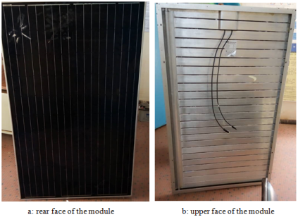
The photovoltaic module is generally composed of a glass which has the role of trapping the radiation, a sheet of EVA (Ethylene Vinyl Acetate) which protects the solar cell against UV radiation and corrosion, solar cells which transform solar radiation into electricity, a layer of Tedlar which protects the photovoltaic cells from bad weather, a junction box and an aluminum frame.
Figure 1 shows the type of PV/T used for the experiment.
Figure 1. Photovoltaic/thermal sensor.
2.2. Materials
Our study will focus on a PV/T sensor. This involves evaluating its performance through the evolution of the temperatures of the different layers of the solar module.
To carry out this study we used:
Thermocouples to monitor the evolution of the temperatures of the different elements of the sensor; a GL 800 type midi logger brand digital recorder.
2.3. Measurement Protocol
The experiments were carried out at the National Center for Scientific and Technological Research (CNRST).
The frequency of the measurement was established at time steps of 10 minutes.
The temperature measurement was carried out with type K thermocouples placed in such a way as to be able to follow the evolution of the following temperatures: The ambient temperature Ta, the temperature of the window Tv a temperature of the absorber Tab, the temperature of the rear face Tcol.
The evolution of solar irradiation Gi was made on the sensor plane with the solarimeter.
3. Modeling of the Photovoltaic/Thermal Sensor
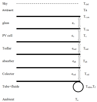
3.1. Thermal Balance of the Thermal Photovoltaic Solar Module
Figure 2 shows the different exchange layers at the level of the sensor studied.
Figure 2. Temperature of the different sensor elements.
The production of electrical and thermal energy by the module depends on several input and output parameters: solar radiation, wind speed, ambient temperature.
The aim of the study is to predict the temperatures in each layer of the module. For this we use the principle of heat conservation for each element of the system which can therefore be presented by the following equation balance:
Storage=input-output
For each element of the sensor we will have:
(1)
3.2. The Exterior Face of the Glass
The exterior face of the glass receives solar energy, it loses part of it by convection with the environment, another by radiation with the sky and transmits part of it by conduction to its interior face. We thus have:
(2)
3.3. Interior Side of the Glass
The exchanges on the interior face of the glass result in:
(3)
3.4. The Solar Cell
The energy balance of the cell becomes:
(4)
3.5. Tedlar Layer
The thermal balance of the Tedlar layer becomes:
(5)
3.6. The Absorbent Plate
The heat balance of the absorbing plate becomes:
(6)
3.7. At the Collector Level
The heat balance of the collectors becomes:
(7)
3.8. At the Tube Level
The heat balance of the tube becomes:
(8)
3.9. The Heat Transfer Fluid
The transfers are then represented by:
(9)
4. Evaluation of Heat Losses from the Sensor
Thermal losses are due to the temperature difference between the different components of the solar collector with the ambient environment. They manifest themselves according to the three modes of heat transfer described previously.
From the equivalent electrical diagram we define:
R1: the thermal resistance between the external environment and the glass,
R2: the thermal resistance between the glass and the cell,
R3: the thermal resistance between the cell and the tedlar,
R'1: the thermal resistance between the tedlar and the absorber,
R'2: the thermal resistance between the absorber and the collectors,
R'3: the thermal resistance between the collectors and the ambient environment.
R'4: Thermal resistance between the tube and the ambient environment.
The overall loss coefficient before
(10)
(14)
(17)
(18)
(19)
The overall exchange coefficient UL is then given by:
5. Sensor Performance
It is given by the following formula:
(21)
Q u is the useful heat coming from the sensor
The solar radiation usable for the thermal system is reduced compared to the case of a thermal sensor alone since a part is converted into electricity by the cells 𝑃𝑉.
(22)
𝐹𝑅 is the heat dissipation factor defined as the ratio of the actual heat flux received by the fluid to that which would be recovered (
15):
(23)
𝐹 ' Sensor efficiency factor given by this formula (
15):
(24)
Electricity production is calculated by:
(25)
PV yield
(26)
(27)
Overall performance
6. Digital Resolution of the System
The equations are solved by the RANGE KUNTA method of order 4.5 using MATLAB software.
The main values used in the simulation are in the following table:
Table 1. Data used for simulation.
Settings | Values |
PV module brand | YADOO SOLAR |
Maximum module power | 250W |
Sensor length | 1,638m |
Sensor width | 0.982m |
Glass transmission coefficient | 0.95 |
glass emissivity | 0.88 |
Glass thickness | 0.0032m |
Baseline Cell Efficiency | 0.15 |
Conductivity thermal glass | 0.93W/Km |
Length of collectors | 0.95 |
Collector width | 0.059 |
Conductivity thermal aluminum | 210W/Km |
Collector thickness | 0.003m |
Conductivity thermal absorber | 0.23 |
Absorber thickness | 0.003 |
PV cell thickness | 0.0003m |
Thermal conductivity of the PV cell | 0.036W/Km |
Cell absorption coefficient | 0.85 |
Thermal conductivity of the tedlar layer | 0.0333W/Km |
Tedlar layer thickness | 0.0005m |
heat mass of glass | 836 J/kg/k |
cell mass specific heat | 836 J/kg/k |
mass specific heat of tedlar | 1400 J/kg/k |
heat mass of the absorber | 1046 J/kg/k |
heat mass of aluminum | 900J/kg/k |
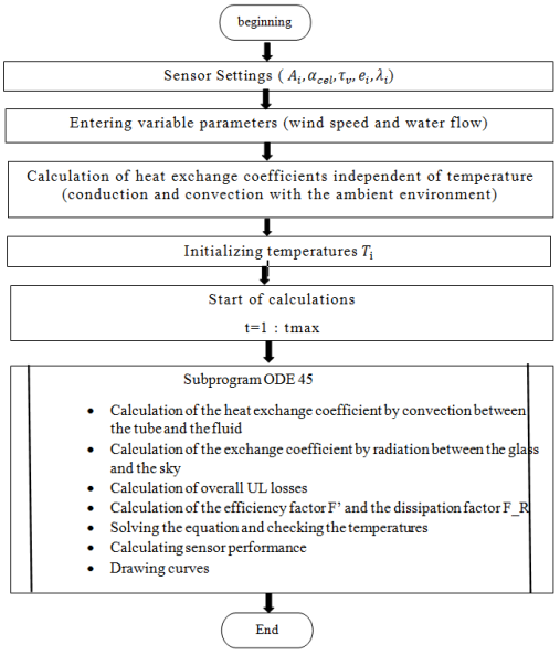
7. Simulation Procedure
The procedure used in the simulation is as follows:
The first step: data introduction:
1) -The different characteristics of the sensor.
2) The second step: calculation of parameters independent of temperature: exchange coefficients by conduction and convection thermal resistance independent of temperature.
3) The third step: we assume that the initial temperatures of the different elements of the sensor are equal to the ambient temperature.
4) The fourth step: calculations of yields and electrical power.
5) The fifth step: displaying the results in the form of a curve.
The steps are summarized in the following algorithm:
Figure 3. Calculation algorithm.
8. Results and Discussion
The study allowed us to develop a mathematical model describing the behavior of the module. Solving the equation system governing heat transfers within the module developed in MATLAB allowed us to calculate the temperature variation for each component. This resolution allows us to estimate the electrical performance of the chosen model.
The results were obtained during the day of September 19, 2023 (cloudy sky).
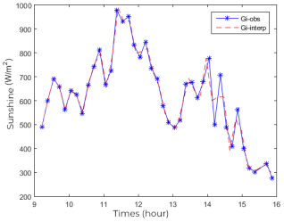
8.1. The Evolution of Solar Radiation
Radiation, being the most important parameter for the operation of the system, its interpolated and experimental evolution is given by the following figure.
Figure 4. Evolution of sunshine as a function of time.
The experimental curve in
Figure 4 for sunshine was interpolated from the experimental value for sunshine with the spline function so as to have the same peaks. Thus, we notice a fluctuation and a decrease in the radiation values which can be explained by cloudy periods and an evolution of the radiation during the day. The maximum value which is 977 W/m² is observed between 11:30 a.m. and 12:30 p.m. while the minimum value 275W/m² is observed at 3:55 p.m.
8.2. Variation of Ambient Temperature
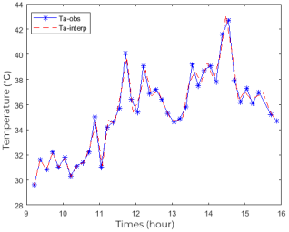
Figure 5 represents the evolution of the interpolated and experimental temperature.
Figure 5. Evolution of temperature as a function of time.
Figure 5 presents the evolution of the experimental and interpolated ambient temperature. The maximum value is 42.7°C at 2:33 p.m. and the minimum value is 29.6°C at 9:13 a.m.
8.3. Distribution of Experimental Temperatures of Glass, Ambient Temperature, Absorber and Back Surface
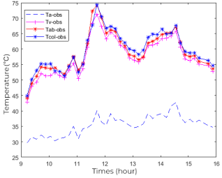
The curves in
Figure 6 show the evolution of the experimental glass temperature, the ambient temperature, the absorber temperature and the rear and sensor temperature over time.
Figure 6. Experimental evolution of the ambient temperature, the window, the rear face and the absorber as a function of time.
In
Figure 6 we notice that the temperatures of the different elements of the sensor and the ambient temperature have practically the same appearance. This is explained by the fact that the temperature of the different layers of the sensor is linked to the ambient temperature. We then notice a small variation in temperature of the different layers of the module due essentially to the small thickness of each layer.
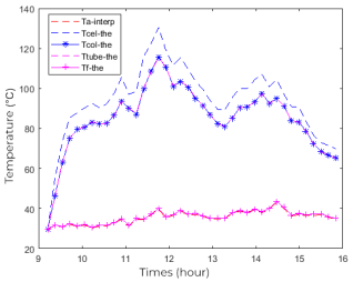
8.4. Influence of the Flow Rate on the Temperature of the Different Layers of the Sensor
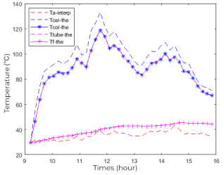
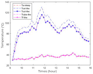
Figures 7 and 8 respectively represent the evolution of the theoretical temperature of the sensor elements at a water volume flow rate of 5 liters/minute and 30 liters/minute for a wind speed of 1m/s.
Figure 7. Temperature profile for a flow rate of 5L/ min versus time.
Figure 8. Temperature profile for a flow rate of 30L/min as a function of time.
Figures 7 and 8 show that a decrease in flow leads to an increase in water temperature. But this does not lead to a drop in temperature of the different layers of the sensor. When the residence time of the water in the sensor is low (high flow rate), its temperature does not vary between the inlet and outlet. However, when the residence time is long (low flow), the fluid recovers maximum heat from the sensor. The sensor studied having only one tube, the heat transfer fluid has a small contact surface with the sensor favoring weak exchange by convection thus the temperature of the fluid is slightly influenced.
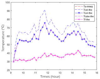
8.5. Influence of Wind Speed on the Temperature of the Different Layers of the Sensor
Wind speed and flow being important parameters of heat exchange, we studied the influence of the variation in wind speed at a constant flow rate of 30 liters/minute of water.
Figures 9 and 10 respectively represent the evolution at a water flow of 30 l/min of the theoretical temperature of the sensor elements for wind speeds of 1m/s and 5m/s.
Figure 9. Variation of the temperature of the different elements of the sensor as a function of time for a wind speed of 1m/s.
Figure 10. Variation of the temperature of the different elements of the sensor as a function of time for a wind speed of 5m/s.
In
Figures 9 and 10, we notice that the sensor elements are influenced by the external environment. Also, we note that the temperatures of the different layers undergo a significant drop of more than 30° C at a wind speed of 5m/s compared to the speed of 1m/s. This is due to the increase in the exchange coefficient by convection of the exterior glass and the rear of the module with the air. This increase in wind speed therefore causes the sensor to cool.
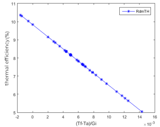
8.6. The Variation of Thermal Efficiency as a Function of Reduced Temperature
Figure 11 shows the linear evolution of thermal efficiency as a function of temperature at a wind speed of 1 m/s and a water flow rate of 5 liters/min.
It is observed that the thermal efficiency decreases with increasing reduced temperature.
Figure 11. Variation of thermal efficiency as a function of reduced temperature.
9. Conclusion
The work carried out within the framework of this article aimed to study, theoretically and numerically, a prototype of a thermal photovoltaic module. The study of the temperature distribution in the different layers of the hybrid sensor made it possible to establish the thermal behavior of the module by numerical simulation.
In summary with this model and from the values of solar irradiation, ambient temperature, wind speed and module parameters, we estimated the performance of the sensor. This work allowed us to know that the surface occupied by the fluid as well as its volume have an effect on thermal efficiency.
Abbreviations
h | Exchange Coefficient Thermal (W/K.m²) |
Vco | Open Circuit Voltage (V) |
Icc | Short Circuit Current (HAS) |
FF | Form Factor |
HAS | Surface (m²) |
T | Temperature * K) |
E | Thickness (M) |
λ | Conductivity Thermal (W/ mK) |
β ref | Module Temperature Coefficient (K -1) |
Cp | Ability Thermal Mass (J/ kg.K) |
Τ | Transmission Coefficient |
Α | Absorption Coefficient |
Author Contributions
Abdoul Aziz Ouiminga: Conceptualization, Data curation, Formal Analysis, Investigation, Methodology, Project administration, Resources, Software, Supervision, Validation, Visualization, Writing – original draft, Writing – review & editing
Bouwèreou Bignan-Kagomna, Funding acquisition, Methodology, Supervision, Validation, Visualization,
Mariatou Zon:, Data curation, Formal Analysis, Funding acquisition, Methodology,
Sié Kam:, Supervision, Validation, Writing – review & editing
Conflicts of Interest
The authors declare no conflicts of interests.
References
| [1] |
McGee, J. A., & Greiner, P. T. (2019). Renewable energy injustice: The socio-environmental implications of renewable energy consumption. Energy Research & Social Science, 56, 101214.
https://doi.org/10.1016/j.erss.2019.05.024
|
| [2] |
Afonja, A. A. (2020). Fossil Fuels and the Environment. ChudacePublishing.
|
| [3] |
Bessou, C., Ferchaud, F., Gabrielle, B., & Mary, B. (2011). Biofuels, greenhouse gases and climate change. Sustainable Agriculture Volume 2, 365-468.
https://hal.science/cirad-00749753
|
| [4] |
Zou, C., Zhao, Q., Zhang, G., & Xiong, B. (2016). Energy revolution: From a fossil energy era to a new energy era. Natural Gas Industry B, 3(1), 1-11.
https://doi.org/10.1016/j.ngib.2016.02.001
|
| [5] |
Han, G., Zhang, S., Boix, P. P., Wong, L. H., Sun, L., & Lien, S. Y. (2017). Towards high efficiency thin film solar cells. Progress in Materials Science, 87, 246-291.
https://doi.org/10.1016/j.pmatsci.2017.02.003
|
| [6] |
Bensalem, S., Imessad, K., Hamidat, A., & Missoum, M. (2016). Active solar heating system for residential building in Algeria An energetic economic and environmental investigation. Journal of Renewable Energies, 19(4), 533-541.
|
| [7] |
Tiwari, A., & Sodha, M. S. (2006). Performance evaluation of hybrid PV/thermal water/air heating system: a parametric study. Renewable energy, 31(15), 2460-2474.
|
| [8] |
Bechouat, M., Younsi, A., Sedraoui, M., Soufi, Y., Yousfi, L., Tabet, I., & Touafek, K. (2017). Parameters identification of a photovoltaic module in a thermal system using meta-heuristic optimization methods. International Journal of Energy and Environmental Engineering, 8, 331-341.
https://doi.org/10.1007/s40095-017-0252-6
|
| [9] |
Khelifa, A., Touafek, K., Kerrour, F., & Haloui, H. (2015). Thermal performance of a photovoltaic thermal collector.
|
| [10] |
Ben Cheikh El Hocine, H., Touafek, K., & Kerrour, F. (2017). Theoretical and experimental studies of a new configuration of photovoltaic–thermal collector. Journal of Solar Energy Engineering, 139(2), 021012.
|
Cite This Article
-
-
@article{10.11648/j.ajee.20241202.13,
  author = {Abdoul Aziz Ouiminga and Bouwèreou Bignan-Kagomna and Mariatou Zon and Sié Kam},
  title = {Study and Simulation of a Thermal Photovoltaic Hybrid Sensor
},
  journal = {American Journal of Energy Engineering},
  volume = {12},
  number = {2},
  pages = {43-52},
  doi = {10.11648/j.ajee.20241202.13},
  url = {https://doi.org/10.11648/j.ajee.20241202.13},
  eprint = {https://article.sciencepublishinggroup.com/pdf/10.11648.j.ajee.20241202.13},
  abstract = {Photovoltaic systems have undergone many recent devel-opments in terms of improving their energy efficiency. One of these performance improvement innovations is: the com-bination of thermal exploitation of solar energy with photo-voltaic exploitation on the same sensor for the simultaneous production of heat and electricity. This study aims to study the electrical and thermal perfor-mances of the system by evaluating the electrical and ther-mal efficiency as well as the electrical power for a hybrid photovoltaic/thermal sensor. In this work, the results of an experimental and numerical study on the thermal behavior of the hybrid sensor are presented and discussed. The experimental study made it possible to determine the electrical characteristics of the PV/T, the sunshine and the ambient temperature for a typical day. The mathematical equations which govern the operating principle of our PV/T are described and solved using the RANGE KUNTA method of order 4 for a numerical study of the efficiency of our PV/T. The numerical results obtained indicate a thermal efficiency of our PVT of 10.5% for a speed of 5 m/s and 7.8% for a speed of 1m/s. Increasing the number of exchange tubes to cover the entire surface of the sensor makes it possible to improve the minimum efficiency from 7.8% to 11.68% for a wind speed of 1m/s. The results obtained suggest that this type of sensor constitutes a good alternative to photovoltaic modules and conventional thermal sensors installed separately.
},
 year = {2024}
}
 Copy
|
Copy
|
 Download
-
TY  - JOUR
T1  - Study and Simulation of a Thermal Photovoltaic Hybrid Sensor

AU  - Abdoul Aziz Ouiminga
AU  - Bouwèreou Bignan-Kagomna
AU  - Mariatou Zon
AU  - Sié Kam
Y1  - 2024/06/25
PY  - 2024
N1  - https://doi.org/10.11648/j.ajee.20241202.13
DO  - 10.11648/j.ajee.20241202.13
T2  - American Journal of Energy Engineering
JF  - American Journal of Energy Engineering
JO  - American Journal of Energy Engineering
SP  - 43
EP  - 52
PB  - Science Publishing Group
SN  - 2329-163X
UR  - https://doi.org/10.11648/j.ajee.20241202.13
AB  - Photovoltaic systems have undergone many recent devel-opments in terms of improving their energy efficiency. One of these performance improvement innovations is: the com-bination of thermal exploitation of solar energy with photo-voltaic exploitation on the same sensor for the simultaneous production of heat and electricity. This study aims to study the electrical and thermal perfor-mances of the system by evaluating the electrical and ther-mal efficiency as well as the electrical power for a hybrid photovoltaic/thermal sensor. In this work, the results of an experimental and numerical study on the thermal behavior of the hybrid sensor are presented and discussed. The experimental study made it possible to determine the electrical characteristics of the PV/T, the sunshine and the ambient temperature for a typical day. The mathematical equations which govern the operating principle of our PV/T are described and solved using the RANGE KUNTA method of order 4 for a numerical study of the efficiency of our PV/T. The numerical results obtained indicate a thermal efficiency of our PVT of 10.5% for a speed of 5 m/s and 7.8% for a speed of 1m/s. Increasing the number of exchange tubes to cover the entire surface of the sensor makes it possible to improve the minimum efficiency from 7.8% to 11.68% for a wind speed of 1m/s. The results obtained suggest that this type of sensor constitutes a good alternative to photovoltaic modules and conventional thermal sensors installed separately.

VL  - 12
IS  - 2
ER  -
Copy
|
Download