Research Article | | Peer-Reviewed

Concrete Shear Walls with GFRP Bars: Simulation and Economic Design

Received: 9 January 2025     Accepted: 24 January 2025     Published: 17 February 2025
Views:       Downloads:
Abstract

Premature corrosion of reinforcing steel is a significant concern for steel-reinforced concrete (RC) structures, often leading to deterioration before reaching their design life. To address this issue, glass fibre-reinforced polymer (GFRP) bars have proven effective as a corrosion-resistant alternative in structural elements such as beams, columns, and slabs. Recent studies have shown that concrete shear walls reinforced with GFRP bars exhibit acceptable performance in terms of ultimate strength. However, compared to conventional steel reinforcement, limited data exist regarding their cracking, deformation, creep susceptibility, long-term performance, and cost. In this paper, a parametric study using a finite-element analysis model, validated against experimental data, was conducted to evaluate the effect of common design variables in GFRP-reinforced concrete shear walls. The study identified optimal design solutions where GFRP-reinforced walls outperform conventional RC walls. The analysis revealed that optimal GFRP designs cost approximately 1.5 times more than steel-reinforced walls, with deflection and crack width emerging as critical factors influencing design feasibility. The use of high-strength concrete was found to have minimal impact on the feasible design region, while bond strength between GFRP bars and concrete significantly influenced crack width and overall performance. Furthermore, creep rupture was determined not to be a critical concern under typical loading conditions. The results highlight that feasible GFRP designs are governed by service conditions, whereas ultimate strength remains the primary constraint for steel-reinforced walls.

Published in American Journal of Civil Engineering (Volume 13, Issue 1)
DOI 10.11648/j.ajce.20251301.13
Page(s) 32-44
Creative Commons

This is an Open Access article, distributed under the terms of the Creative Commons Attribution 4.0 International License (http://creativecommons.org/licenses/by/4.0/), which permits unrestricted use, distribution and reproduction in any medium or format, provided the original work is properly cited.

Copyright

Copyright © The Author(s), 2025. Published by Science Publishing Group

Keywords

Reinforced Concrete, Shear Walls, GFRP, Finite-Element Analysis, Optimal Design

1. Introduction
Steel reinforcement is highly susceptible to corrosion, especially in aggressive environments such as coastal areas, industrial zones, and regions with high humidity or de-icing salts. This corrosion compromises the structural integrity of reinforced concrete (RC) structures and leads to increased maintenance costs and reduced service life. In the early 1960s, the issue of steel reinforcement corrosion led to the investigation of using fiber-reinforced polymer (FRP) to replace steel reinforcement in RC structures . Unlike steel, which is prone to oxidation in the presence of moisture and chlorides, FRP bars are non-corrosive due to their composite nature. The absence of electrochemical processes that lead to corrosion in steel means that FRP-reinforced structures can maintain their integrity over extended periods, even in harsh conditions.
Various types of FRP reinforcement have been introduced, including carbon (CFRP), aramid (AFRP), basalt (BFRP), and glass (GFRP). Although CFRP offers the highest tensile strength, it is also the most expensive, while GFRP provides a more economical alternative, with tensile strength comparable to mild steel but at a significantly lower cost relative to CFRP. Consequently, GFRP holds substantial promise as a replacement for steel reinforcement, balancing performance and affordability.
Early research on FRP-reinforced concrete has primarily focused on horizontal members such as beams and slabs. These studies indicate that FRP-reinforced beams can achieve higher ultimate flexural capacity than steel-reinforced counterparts with the same reinforcement ratio due to the higher tensile strength of FRP bars . However, because FRP bars generally have a lower elastic modulus, their cracked stiffness is reduced, resulting in wider cracks and larger deflections during service .
Similar observations hold for shear-critical beams and slabs, where concrete strength, shear span ratio, longitudinal reinforcement ratio, and stirrup configuration are significant factors influencing shear capacity . Columns confined by FRP ties provide adequate confinement and restraint against buckling .
Despite these advances, research specifically targeting FRP-reinforced shear walls remains limited. Yamakawa and Fujisaki conducted a study on one-third-scale shear walls reinforced with carbon FRP (CFRP) grids, finding early degradation in lateral load capacity and low energy dissipation. These issues were attributed to the inability of CFRP grids to withstand compressive stress, insufficient development length, and lack of concrete confinement.
Recent numerical and experimental studies further corroborate the feasibility of GFRP reinforcement for shear walls. Hybrid GFRP–steel shear walls and entirely GFRP-reinforced systems have achieved comparable strength and stiffness levels to their steel-reinforced counterparts while benefiting from corrosion resistance . Notably, of GFRP-reinforced walls can maintain decent ductility and lower residual displacements when properly detailed, although they may exhibit increased brittleness and reduced energy dissipation. Some studies have shown that at least 85% of the steel-reinforced wall strength can be achieved by GFRP-reinforced walls using different materials (e.g., seawater sea-sand concrete) or hybrid reinforcement strategies . Additionally, the dynamic (seismic) behavior of GFRP-reinforced walls has become an area of growing interest, as the linear elasticity of FRP bars may reduce hysteretic energy losses but can also minimize residual deformations after seismic events, thereby facilitating faster reoccupation .
In addition to demonstrating improved corrosion resistance and moderate ductility, FRP-reinforced shear walls show potential for self-centering capabilities . These studies highlight the critical role of axial compression, reinforcement arrangement, and boundary detailing in reducing residual displacements under cyclic loading. Comprehensive parametric evaluations—ranging from finite-element simulations to deep learning frameworks—have further underscored the importance of systematically optimizing material parameters and geometric configurations in FRP-reinforced systems . Nonetheless, the higher initial cost of FRP relative to steel remains a barrier to widespread implementation, placing emphasis on life-cycle cost assessment and efficient design strategies . Although more full-scale experimental data are needed to validate these approaches, the findings of recent research suggest that GFRP reinforcement, alone or in combination with steel, can be a viable alternative to conventional steel reinforcement in shear walls—especially in aggressive environments where corrosion is of paramount concern.
Building on these observations, a major challenge in the practical implementation of FRP reinforcement, especially GFRP bars, is their higher initial cost relative to standard steel. It has been noted that GFRP bars can be two to three times more expensive on a per-unit-weight basis—an upfront premium that many stakeholders may find prohibitive . Where long-term durability benefits do not immediately offset this higher cost, GFRP adoption may be delayed or curtailed. Nevertheless, GFRP reinforcement can significantly reduce the frequency and extent of repairs associated with steel-reinforced structures in aggressive environments, thereby favorably influencing overall life-cycle costs. This benefit is particularly evident in applications where frequent maintenance or premature replacement of corroded steel would incur substantial expense. As such, optimizing the design of GFRP-reinforced shear walls can result in both technical and economic advantages over a structure lifespan . Consequently, refining GFRP usage to attain performance on par with steel while minimizing material demands is crucial to making FRP-reinforced shear walls economically viable.
This research aims to explore design scenarios in which GFRP reinforcement can be used in shear wall structures with comparable performance to conventional steel reinforcement in a cost effective manner, focusing on non-seismic areas where the dynamic performance requirements are less stringent. A finite-element analysis (FEA) model was developed to simulate the flexural behavior of slender shear walls, validated with the experimental tests conducted by Mohamed et al. . A parametric study was conducted to evaluate the impact of typical design constraints—strength, deflection, cracking, cost, and long-term performance—on the feasibility of GFRP-reinforced shear walls. The study also explored the effects of using high-strength concrete and full bonding between GFRP bars and concrete. Additionally, a comparative analysis was performed between steel-reinforced and GFRP-reinforced shear walls to assess their relative performance. By examining these factors, the research aims to identify optimal design solutions that satisfy performance requirements while remaining cost-effective.
2. Analysis Model for FRP-reinforced Shear Walls
Effective numerical frameworks for modeling reinforced concrete membrane components under combined in-plane and shear stresses are offered by Vecchio . In this study, a two-dimensional model of a concrete shear wall reinforced with GFRP bars was created using the VecTor2 finite-element software, which incorporates both strategies .
Concrete walls in this modeling technique were represented by quadrilateral elements. The stress-strain relationship outlined by Hoshikuma et al. was used to characterize the compressive behavior of the concrete both before and after peak. The concept proposed by Vecchio and Lai was used to account for slip-induced distortions in reinforced concrete. According to Bentz , tension stiffening effects were incorporated, and the Kupfer’s model was used to calculate the confinement contribution. The Mohr-Coulomb criteria and the Variable-Kupfer model were used to cracking and dilatation behavior, respectively.
Sanded glass-FRP (GFRP) bars are the type of FRP reinforcement taken into consideration in this study, and their response was assumed to be linear. The compressive modulus of elasticity for GFRP was determined to be equal to the modulus of elasticity in tension (EgT=EgC=E), while the compressive strength of GFRP material (fguC) was taken as 50% of the ultimate tensile strength (fguT) . For the GFRP reinforcement, which was represented as 1D truss components joined to the concrete by zero-length link elements, dowel action was disregarded.
The bond-slip interaction (Figure 1) between the GFRP bars and the concrete was simulated using the stress-slip model proposed by Eligehausen et al. , which exhibits characteristics like the bond-slip curve for sanded GFRP bars described by Cosenza et al. . A mesh-size sensitivity assessment helped determine a suitably refined mesh that could capture localized cracking patterns without excessive computational cost, leading to close agreement between the numerical predictions and the experimental outcomes.
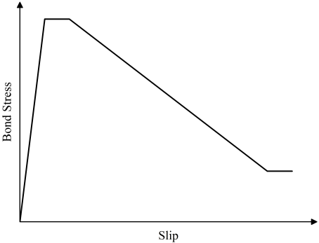
Figure 1. Eligehausen bond stress-slip response.
Mohamed et al. examined three GFRP-reinforced concrete shear walls. Quasi-static loading was used to test the specimens failure. The wall specimens were created in accordance with ACI 440 and CSA S806 . Figure 2 displays the cross-section dimensions and reinforcement arrangement for the tested shear-wall specimens.
The reinforcement ratios are listed in Table 1. Based on the confined concrete core (140*140 mm) and excluding the concrete cover, ρ and ρb represent the vertical reinforcement ratios in the web and boundaries, respectively; ρh represents the horizontal reinforcement ratio in the wall web; and ρt represents the horizontal reinforcement ratio at the boundaries.
Table 1. Reinforcement ratios of GFRP-reinforced shear walls.

Walls

ρ

ρb

ρh

ρt

G15

0.58

1.43

1.58

0.89

G12

0.62

1.43

1.58

0.89

G10

0.59

1.43

1.58

0.89

The GFRP bars were selected to have properties consistent with those specified in CSA S807 and were high-modulus, sand-coated glass FRP bars. Table 2 displays the characteristics of the GFRP bars. The concrete tensile (ft) strength was 3.5 MPa, while its compressive strength (f'c) was 40 MPa.
Table 2. Properties of GFRP bars.

Bars

(mm)

(mm2) 

(GPa)

fu (MPa)

Ɛu (%)

GFRP #3

9.5

71.3

66.9

1412

2.11

GFRP #4

12.8

126.7

69.6

1392

2

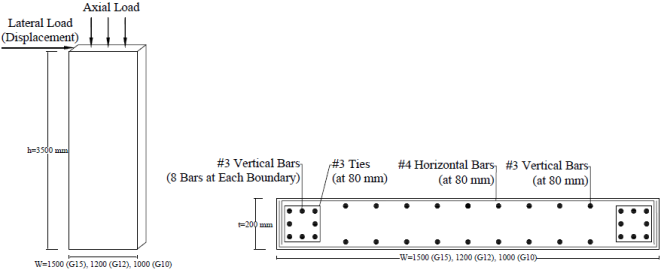
Figure 2. Concrete dimensions and reinforcement configuration of GFRP reinforced concrete shear walls .
The load was applied in a displacement-controlled, cyclic manner that followed the load-displacement protocol in the experiment. Figure 3 presents the response envelopes from both FEA and experimental tests for walls G10, G12, and G15. Comparing the ultimate load capacities estimated by VecTor2 with the experimental results demonstrates that VecTor2 accurately predicts the flexural behavior of GFRP-reinforced shear walls within an acceptable margin of error.
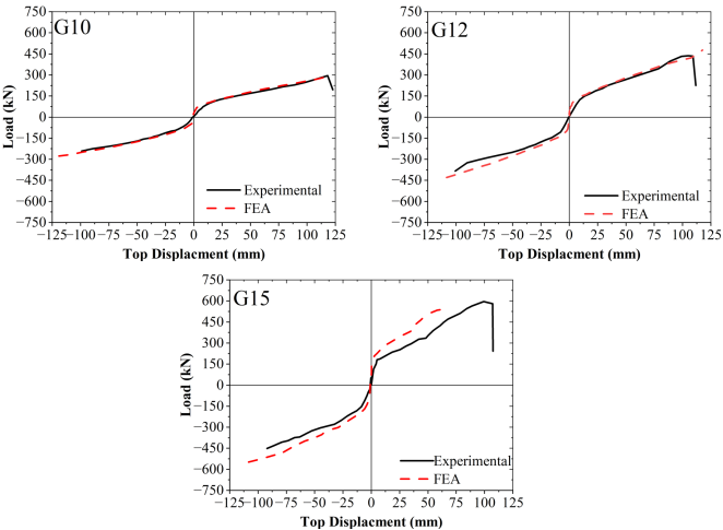
Figure 3. Lateral load versus top-displacement relationship for Experimental and FEA.
3. Parametric Study
Although GFRP bars in reinforced concrete structures offer advantages such as high strength and excellent corrosion resistance compared to conventional steel reinforcement, their market adoption remains limited. This is due to factors including their perceived high cost, uncertainties regarding long-term performance, and the differing design principles required compared to traditional steel rebar . Demonstrating the feasibility of using GFRP reinforcement involves identifying ranges of common design variables where GFRP can achieve comparable performance to steel-reinforced concrete structures while minimizing costs.
To achieve this, the influence of common design constraints was analyzed through a parametric study focusing on ultimate strength and serviceability limit states. Then, the results for GFRP-reinforced concrete walls were compared to a reference steel-reinforced wall. This approach enables the identification of feasible regions where GFRP-reinforced walls meet or exceed the performance of steel-reinforced walls. This technique was first used by Al-Salloum and Husainsiddiqi to determine the most economical design of the singly steel-reinforced rectangular beams built as per ACI 318 . Balafas and Burgoyne used a similar tool to investigate the feasibility of using FRP reinforcement in beams using the same technique for T-beams reinforced with FRP bars. They defined the feasible region for FRP-reinforced members by plotting the beam depth vs. the percentage longitudinal reinforcement. This study used similar plots, using the wall length vs. vertical reinforcement ratio (w-ρ). The assumed material properties for the steel and GFRP materials used in the analysis are shown in Table 3.
Table 3. Material properties of reinforcement.

Material

E(GPa)

fy (MPa)

fu (MPa)

Ɛy (%)

Ɛu (%)

GFRP

66.9

-

1412

-

2.11

Steel

200

400

550

0.2

-

3.1. Reference Wall
A 9-storey high, an exterior steel-reinforced concrete shear wall assumed to be part of the load resisting system of a building in a non-seismic zone was designed to comply with the requirements specified in CSA A23.3 and ACI 318 . This wall is used as a reference wall and was chosen to be exterior wall as it is more vulnerable to corrosion. The reference wall height, width, and thickness were arbitrarily chosen as 27000 mm, 6750 mm, and 200 mm, respectively. The vertical and horizontal reinforcement ratios were 1.0 and 1.5 percent, respectively. These ratios were selected arbitrarily, as the focus of the research is not on the detailed design of conventional RC walls for specific regional loads but rather on comparing the performance of FRP- and steel-reinforced walls. Nonetheless, a survey of structural engineers indicated that these ratios are representative of designs commonly used in regions with high wind pressures . The vertical and horizontal reinforcement ratios also comply with the minimum reinforcement requirements specified in CSA A23.3 , which are 0.15% and 0.2%, respectively. The gravity load, 𝑁, applied to the wall was set at 7% of its gross section capacity, aligning with typical values for walls in low- to mid-rise RC buildings . It is assumed that the building deformation is governed by flexural behavior, with the walls acting as vertical cantilevers to resist lateral forces. The nonlinear responses are primarily concentrated in the lower stories of the structure.
3.2. GFRP-reinforced Walls
In the parametric study of GFRP-reinforced walls, key parameters such as wall width, reinforcement ratios, and material properties were varied to evaluate their impact on performance. These parameters were chosen because they can be adjusted by the structural designer without significantly affecting architectural constraints. In contrast, the height and thickness of the walls were kept constant to match the reference wall, simplifying comparisons. The analysis model discussed in Section 2 was used to investigate the behavior of GFRP-reinforced walls with varying widths and reinforcement ratios. Wall widths (w) ranged from 4,500 mm to 13,500 mm, resulting in height-to-width ratios of 2 to 6. This range ensures that the walls are slender and flexural failure is achieved. In addition, the horizontal reinforcement for the walls were selected to prevent shear failures. The wall thickness was maintained at a constant value of 200 mm for all designs. This thickness satisfies the minimum requirements specified in CSA A23.3 and ACI 318 to prevent out-of-plane buckling in shear walls. According to these provisions, the minimum thickness should be at least hs/25, where hs is the unsupported height of the wall. For the building under consideration, the unsupported height corresponds to the story height of 3 meters, resulting in a minimum thickness of 120 mm. Figure 4 shows the schematic cross-section dimensions and the reinforcement details of the shear walls. The wall design is assumed to be typical of non-seismic regions and assumed to be governed by wind forces.
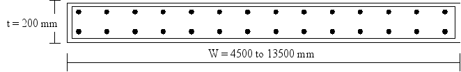
Figure 4. Dimensions of GFRP-reinforced walls used in the parametric study.
4. Results
4.1. Ultimate Strength Constraint
A FEA analysis model of the reference RC wall was developed, and a pushover analysis was conducted to determine the ultimate lateral strength. The ultimate strength was defined as the peak load capacity. For the reference wall, this was determined as 1112 kN. Analysis models were then developed for the GFRP-reinforced walls with varying widths and vertical reinforcement ratios. Figure 5a illustrates the ultimate strengths of the GFRP-reinforced walls across different wall widths and reinforcement ratios. The recorded ultimate strength in kN is indicated by the numbers adjacent to the marks. Cross markings indicate walls that are as strong as or stronger than the reference wall, whereas round markers indicate walls that are not strong enough. The "strength constraint" line distinguishes the boundary between walls that meet the strength requirement (above the line) and those that do not (below the line). The shaded region in the figure represents the feasible zone, where GFRP-reinforced walls satisfy the ultimate strength requirement and can be considered viable for further design evaluations.
In general, there is a negative correlation between wall width and reinforcement ratio along the strength constraint line. Increasing the reinforcement ratio reduces the wall width required to achieve the same strength as the reference wall. At lower reinforcement ratios (e.g., 0.2%), the slope of the strength constraint line is steep, indicating a higher sensitivity of wall width to reinforcement ratio in achieving the same resistance as the reference wall. However, as the reinforcement ratio increases, the slope of the constraint line flattens, suggesting that increasing the reinforcement ratio beyond a certain threshold has a diminishing effect on ultimate strength. This behavior is further explained in the following section.
4.2. Balanced Sections Constraint
Because GFRP bars do not exhibit yielding or an equivalent mechanism, design codes specify that failure must be governed by the crushing of concrete in compression rather than fracture of the tensile reinforcement . For each wall, a minimum level of reinforcement—referred to as the balanced reinforcement ratio—ensures that failure is controlled by concrete crushing. This balanced ratio corresponds to a line on the (𝑤-𝜌) diagram, labeled the “Balanced Section” constraint (Figure 5b). Simple plane-sectional analysis shows that, for a rectangular cross-section with uniformly distributed reinforcement, the balanced reinforcement ratio remains constant . This explains that the flattened slope of the strength constraint line as the failure is governed by concrete crushing and increasing GFRP reinforcement will not enhance the strength significantly.
4.3. Serviceability Constraints
The serviceability of RC elements can be characterized by deflection and cracking service limit states. Deflections and crack widths must remain within permissible limits. The reinforcement type significantly affects the amount of deflection and cracking in reinforced concrete members. FRP-reinforced concrete structures exhibit larger deflections and wider crack widths compared to those reinforced with a comparable amount of steel due to the lower Youngs modulus of FRP .
4.3.1. Deflection at Service
The service deflection was controlled using two criteria. The first criterion specifies that the wall deflection under service load must not exceed the maximum allowable service displacement prescribed by the applicable building code. For example, according to the NBCC , the service displacement limit is ℎ/500, equivalent to 54 mm in this case. Similarly, ASCE 7 establishes a limit of ℎ/400, corresponding to 67.5 mm in this instance.
Service deflection is defined by the second criterion as the amount that corresponds to the maximum permissible stresses of the materials (FRP, steel, and concrete). The maximum tensile stress in the steel bars for RC walls was set to 0.6fy, while the concrete compressive stress under service loads was limited to 0.4f’c. The FEA showed that the minimum service load was controlled by service stresses in the concrete, leading to a service load of 546 kN and an associated deflection of 25 mm at the top of the wall. This deflection was assumed to be the controlling service limit state, as it was smaller than that corresponding to the h/500 limit by NBCC. According to ACI 440 , the service stresses in the FRP material for GFRP-reinforced walls were limited to 25% of its ultimate tensile strength. As a result, the allowable service FRP stress was 353 MPa.
At the service load determined for the reference steel-reinforced wall (546 kN), all the GFRP-reinforced walls that exhibited deflections lesser than the maximum allowable service displacement (54 mm) while simultaneously exhibiting material (concrete and GFRP) stresses smaller than their allowable limits, were deemed to be acceptable design options. Walls with larger deflections or exceeding the service stresses in the materials were considered unacceptable. The boundary line that divided the feasible and unfeasible alternatives created the deflection constraint (Figure 5c). This boundary line reduced the feasible zone area, as the walls examined in the parametric study were governed by allowable deflections rather than strength.
4.3.2. Crack Width at Service
Crack widths in RC structures should be restricted primarily to prevent corrosion, moisture penetration, and an unat-tractive appearance. In structures reinforced with FRP, crack widths tend to be larger than those in steel-reinforced struc-tures when subjected to similar loads, owing to the lower modulus of FRP compared to steel. Similar to traditional RC, increasing the FRP reinforcement ratio can help minimize crack widths . However, when specific conditions such as water-tightness are not a concern, the maximum allowable crack width for FRP-reinforced structures can be more relaxed than for standard RC, given that FRP is not susceptible to corrosion. This is acknowledged in the provi-sions established by CSA S806, which permits crack widths of 0.5 mm and 0.7 mm for exterior and interior envi-ronments, respectively, whereas the limits for steel-reinforced concrete are 0.3 mm and 0.4 mm.
To assess how crack width influences the feasible region, the maximum crack width for each GFRP reinforced wall was calculated using the FEA model at the service load defined for a reference wall. Walls with crack widths at or below the allowable limit of 0.5 mm (for exterior exposure) were classified as being within the feasible zone. In contrast, those that exceeded this limit were viewed as failing to meet the crack width criteria under service conditions, as illustrated in Figure 5d. As anticipated, the feasible region comprises walls with higher reinforcement ratios, resulting in closer bar spacing and narrower cracks.
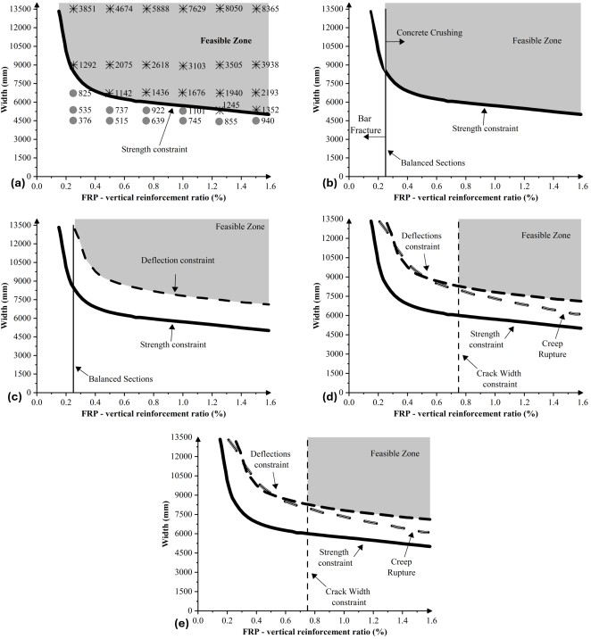
Figure 5. Relationship between GFRP-reinforced wall width and vertical reinforcement ratio with different constraints: a) Strength, b) Balanced sections, c) Deflection, d) Crack Width, and e) Creep rupture.
4.4. Long-term Performance
FRP materials exhibit a long-term strength significantly lower than their short-term strength under static load when subject to sustained tensile stresses . The degradation in FRP strength is called creep rupture, an effect that has been observed to be more significant for GFRP than CFRP composites . Long-term creep effects must be accounted for in the design of beams and slabs since most of their reinforcement experiences tension during sustained loading. For a shear wall, however, most of the compressive loads (dead and live load) are sustained, while the loads that cause tension in the reinforcement, such as wind and earthquakes, are transient. Therefore, if no sustained loading produces tension in the FRP bars, these should not be affected by creep, and the entire cross-section is expected to be entirely under compression. To illustrate, however, the effect of the creep constraint if the lateral loads are sustained, a long-term creep reduction in stress caused by creep was incorporated into the GFRP bars. Balafas and Burgoyne proposed Eq. 1 to calculate the tensile stress of FRP reinforcement, modified due to creep failure, depending on the time th, in hours:
ft=fi(1-βlogth) (1)
Where fi is the initial FRP strength and ft shows the strength after time th. β is a 0.101 for GFRP bars . According to CSA S806 , the strength of GFRP bars against creep rupture over a million hours should be greater than 35% of the ultimate tensile strength. In this study, the residual strength calculated based on the CSA criteria was 492 MPa, whereas Eq. 1 provided a less conservative estimate of 556 MPa, which was applied in the FEA model. Figure 5e shows that even if the bars are assumed to be subjected to sustained tensile forces, as long as the deflection requirements are met, creep is not a critical concern in the design of GFRP-reinforced shear walls.
5. Discussion
5.1. Cost Function
To determine the most cost-effective design for shear walls in the w-ρ diagram, the cost function (CF) must account for the expenses associated with flexural reinforcement and concrete, excluding the costs for horizontal reinforcement and formwork , as follows:
Cw,ρ=Ccw×t×1-ρ×h+Cgw×t×ρ×h(2)
Where Cc and Cg are the unit costs ($/mm2/m) of concrete and GFRP, respectively. The parameters w, t, and h represent the wall width (mm), thickness (mm), and height (m), respectively. The average unit costs for the materials used in the CF are provided in Table 4, which reflects data from a manufacturer survey conducted in 2017. The equation for the CF pertaining to GFRP-reinforced concrete shear walls is formulated in Eq. 3.
Cw,ρ=116.856 ρw+1.35 w(3)
Table 4. Material costs.

Material

Cost ($/mm2/m)

Concrete

Cc=0.00025

GFRP

Cg=0.02189

Steel

Cs=0.00841

The optimal design solution for GFRP-reinforced shear walls can be obtained graphically by using Eq. 3. The chart in Figure 6 illustrates the CFs for shear walls at three price points: $15,000, $18,400, and $22,000. Each line in the graph represents numerous potential wall designs that share the same cost but vary in reinforcement ratios and concrete dimensions. In this case, walls costing $15,000 will not satisfy the design requirements as their CF is not intersecting the feasible zone. The optimum solution is the point or the points where the CF line meets the feasible zone at the lowest price. In this case, the optimal solution of GFRP-reinforced shear walls is located at the intersection of the crack width and deflection constraints, costing $18,400.
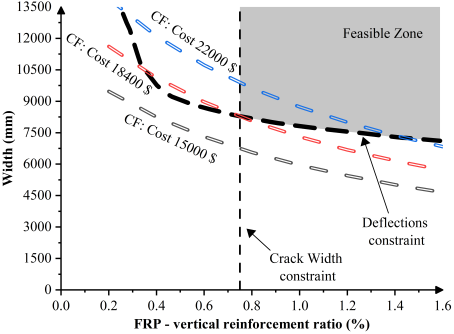
Figure 6. Flexural optimal solution for GFRP reinforced shear walls.
5.2. Effect of Using High-Strength Concrete in GFRP-reinforced Walls
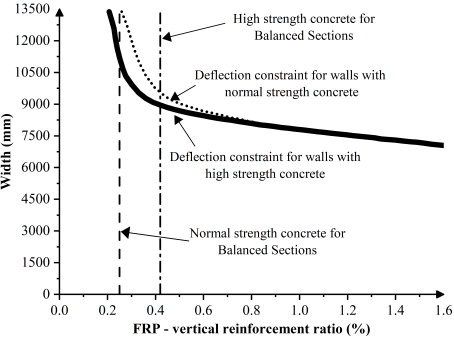
Figure 7. The effect of high-strength concrete on the deflection constraint.
The low Young's modulus of GFRP makes deflection at service levels a significant concern in GFRP-reinforced concrete walls when compared to other constraints. One solution to maintain deflections within permissible limits is the use of high-strength concrete . The guidelines provided in CSA S807 permit a maximum concrete strength of 80 MPa for designing FRP-reinforced concrete structures. In reinforced flexural members utilizing high-strength concrete, the constraints of a balanced section are more stringent than in those using normal-strength concrete. This is due to the greater amount of tension reinforcement required to counterbalance the compression forces in high-strength concrete applications. Consequently, the balanced section line shifts to the right in the w-ρ diagram, as illustrated in Figure 7, further narrowing the feasible area. Ultimately, the advantages of using high-strength concrete in GFRP-reinforced walls appear to be minimal.
5.3. Effect of Bond Between GFRP Bars and Concrete
Another important factor affecting crack width in RC structures is the bond between the reinforcing bars and the concrete . In flexural elements featuring FRP bars, which possess a lower modulus of elasticity compared to steel, the reduced bond strength can lead to larger crack widths . This results in a more stringent constraint on crack width and limits the range of design solutions.
To explore the impact of bond strength on crack width in walls, a simplified analysis was performed. The bond model applied for this assessment is based on the Eligehausen model , which is recommended for scenarios involving sanded FRP bars. To assess the upper extremes of bond stresses, a perfect bond between concrete and GFRP bars was assumed, particularly in situations where mechanical enhancement of adhesion occurs, such as with ribbed bars. The model employs a common-node approach to achieve the ideal bond scenario.
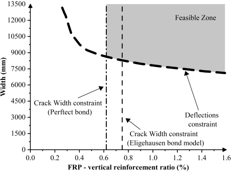
Figure 8. Crack width constraint comparison between walls with perfect and intermediate bonds for GFRP bars.
As illustrated in Figure 8, assuming a perfect bond between GFRP bars and concrete results in a less stringent crack width constraint, shifting it leftward in the w-ρ diagram. This adjustment increases the area of feasible solutions and offers a more cost-effective alternative compared to the ideal flexural solutions for GFRP-reinforced shear walls, particularly under conditions of intermediate bonding.
5.4. Comparison of GFRP and Steel-Reinforced Shear Walls
In this section, a comparison is made between the w-ρ diagrams for shear walls reinforced with GFRP and those reinforced with steel. Figure 9 illustrates the design limitations for both types of shear walls. The analysis indicates that the strength constraint for steel-reinforced shear walls is more stringent than GFRP-reinforced shear walls. This is due to steel reinforcement having a lower ultimate strength compared to GFRP, resulting in lower ultimate capacities for the steel-reinforced walls. The modulus of elasticity of GFRP is less than that of steel, making the deflection constraint for GFRP-reinforced walls more critical and thus reducing the feasible region. The requirement for controlling crack width is less severe in steel-reinforced shear walls, with the minimum reinforcement ratio necessary to control crack widths being two-thirds of that needed in GFRP-reinforced walls.
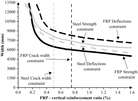
Figure 9. Comparison of design constraints of steel and GFRP reinforced concrete shear walls.
Figure 10 presents the allowable limits for steel reinforcement in shear walls as specified by the CSA A23.3 standard, which identifies a minimum reinforcement area to prevent excessive cracking, as well as a maximum reinforcement ratio, known as the balanced reinforcement ratio, to ensure that the tension reinforcement yields before the concrete experiences crushing. Although the range for the allowed reinforcement ratios in steel reinforced walls is wide, it is capped at a maximum value, which is not the case for the GFRP reinforced walls as the preferred failure mode is always concrete crushing which remove any upper limits for having GFRP reinforcement ratio.
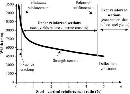
Figure 10. Reinforcement limits for steel-reinforced shear walls.
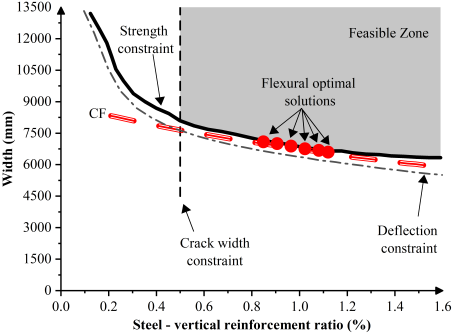
Figure 11. Feasible zone and CF for steel-reinforced shear wall.
Table 5. Comparison of the optimal design solution costs (GFRP and Steel reinforced shear walls).

Shear walls

Cost of the optimal design solutions ($)

GFRP-reinforced

18400

Steel-reinforced

12000

Figure 11 shows the design limitations and feasible zones for steel-reinforced shear walls. Comparatively, the optimal design for steel-reinforced walls is less costly than for their GFRP counterparts, as detailed in Table 5. Although the initial investment for GFRP bars is approximately three times that of steel bars, the total cost for the optimal design of GFRP shear walls in this study is about 1.5 times higher than that of steel-reinforced walls. It is also important to note that this analysis does not take into account long-term expenses related to the repair, maintenance, or replacement of steel-reinforced concrete structures that are vulnerable to corrosion.
6. Conclusions
This research utilized a validated finite-element analysis alongside established theoretical and computational models to predict the behavior of GFRP-reinforced concrete shear walls. A parametric study was conducted using this model to explore the effects of standard design limitations, represented through charts that link the flexural reinforcement ratio to wall width. The case study focused on a nine-story reinforced concrete structure, measuring 27 meters in height. The shear walls examined were the external structural wall of the building, identified as a slender wall. The study assessed a range of design constraints such as strength, balanced sections, deflections, crack widths, and creep. The investigation conceded several conclusions:
1) The finite-element application of the Modified Compression Field Theory demonstrated its effectiveness in accurately simulating the behavior of concrete shear walls reinforced with GFRP, particularly concerning their strength, deflection, crack formation, and failure modes.
2) The feasible design region for GFRP-reinforced shear walls is influenced by the balance between wall width and reinforcement ratio. Increasing the reinforcement ratio reduces the required wall width, but its impact on strength diminishes at higher ratios due to the governing failure mode of concrete crushing.
3) Deflection and crack width are critical factors for GFRP-reinforced walls. The lower modulus of elasticity of GFRP leads to stricter deflection and crack width constraints, reducing the feasible design region. Higher reinforcement ratios help reduce crack widths, meeting serviceability limits.
4) Creep rupture is not a critical issue for GFRP-reinforced walls under typical loading conditions, as sustained loads primarily induce compression. Even under hypothetical sustained lateral loads, the residual tensile strength of GFRP bars remains sufficient for design.
5) The cost function analysis highlights that the optimal design solution for GFRP-reinforced shear walls is located at the intersection of deflection and crack width constraints.
6) Using high-strength concrete can mitigate deflection issues associated with GFRP-reinforced walls. However, the benefits are minimal as the balanced section constraints become more stringent, requiring greater amounts of reinforcement to balance the higher compressive forces.
7) The bond between GFRP bars and concrete plays a critical role in controlling crack widths. Improved bond strength, such as that achieved with ribbed or sanded GFRP bars, shifts the crack width constraint leftward in the w-ρ diagram, increasing the feasible design region and offering cost-effective solutions.
8) GFRP-reinforced walls have less stringent strength constraints than steel-reinforced walls due to their higher ultimate strength. However, the lower modulus of elasticity of GFRP results in stricter deflection constraints, reducing the feasible design region.
Although the initial cost of GFRP reinforcement is almost three times higher than that of steel, the optimal design solution of the GFRP reinforced shear wall found in this study was marginal, about 1.5 times more expensive than steel reinforced shear walls. However, the study has some limitations that should be considered. Its scope is limited to non-seismic regions, which restricts the applicability of its findings to areas with higher structural demands, such as seismic zones. Additionally, while cost analysis was included, a detailed evaluation of the potential life-cycle savings and long-term economic benefits of GFRP reinforcement was not addressed. Future research could expand the scope and impact, particularly in exploring seismic performance and detailed life-cycle cost analysis.
Abbreviations

EgT

Tensile Elastic Modulus of GFRP

EgC

Compressive Elastic Modulus of GFRP

E

Elastic Modulus of the Reinforcement

fguC

Compressive Strength of GFRP

fguT

Tensile Strength of GFRP

ρ

Vertical Reinforcement Ratio in the Web of the Wall

ρb

Vertical Reinforcement Ratio in the Boundaries of the Wall

ρh

Horizontal Reinforcement Ratio in the Web of the Wall

ρt

Horizontal Reinforcement Ratio in the Boundaries of the Wall

fc

Compressive Strength of Concrete

N

Total Gravity Load Acting on the Wall

w

Length of the Wall

t

Thickness of the Wall

h

Height of the Wall

d

Diameter of the Bar

A

Cross-sectional Area of the Bar

fy

Reinforcement Yield Stress

Fu

Reinforcement Ultimate Strength

Ɛy

reinforcement Yield Strain

Ɛu

Reinforcement Ultimate Strain

Cc

Unit Cost of Concrete

Cg

Unit Cost of GFRP

Cs

Unit Cost of Steel

fi

Initial GFRP Strength

ft

GFRP Strength After Time th

th

Time in Hours

β

Creep Constant

Acknowledgments
A part of this research was funded by Natural Sciences and Engineering Research Council, NSERC, of Canada.
Conflicts of Interest
The authors declare no conflicts of interest.
References
[1] L. Xing, S. Sun, K. Mei, Y. Guo, and Z. Yang, “Research progress on short-term mechanical properties of FRP bars and FRP-reinforced concrete beams,” *J. Traffic Transp. Eng. (English Ed.)*, vol. 11, no. 2, pp. 245–270, 2024,
[2] C. Kassem, A. S. Farghaly, and B. Benmokrane, “Evaluation of flexural behavior and serviceability performance of concrete beams reinforced with FRP bars,” *J. Compos. Constr.*, vol. 15, no. 5, pp. 682–695, 2011,
[3] F. Elgabbas, P. Vincent, E. A. Ahmed, and B. Benmokrane, “Experimental testing of basalt-fiber-reinforced polymer bars in concrete beams,” *Compos. B Eng.*, vol. 91, pp. 205–218, 2016,
[4] M. N. Habeeb and A. F. Ashour, “Flexural behavior of continuous GFRP reinforced concrete beams,” *J. Compos. Constr.*, vol. 12, no. 2, pp. 115–124, 2008,
[5] I. F. Kara, A. F. Ashour, and C. Dundar, “Deflection of concrete structures reinforced with FRP bars,” *Compos. B Eng.*, vol. 44, no. 1, pp. 375–384, 2013,
[6] M. Kazemi, R. Madandoust, C. Chastre, M. R. Esfahani, and L. Courard, “Numerical study on the flexural behaviour of normal- and high-strength concrete beams reinforced with GFRP bar, using different amounts of transverse reinforcement,” *Structures*, vol. 34, pp. 3113–3124, 2021,
[7] Md. A. Chowdhury, Z. I. Zahid, and Md. M. Islam, “Development of shear capacity prediction model for FRP-RC beam without web reinforcement,” *Adv. Mater. Sci. Eng.*, vol. 2016, no. 1, pp. 1–19, 2016,
[8] M. Z. Afifi, H. M. Mohamed, and B. Benmokrane, “Axial capacity of circular concrete columns reinforced with GFRP bars and spirals,” *J. Compos. Constr.*, vol. 18, no. 1, p. 04013017, 2014,
[9] N. Mohamed, A. S. Farghaly, B. Benmokrane, and K. W. Neale, “Experimental investigation of concrete shear walls reinforced with glass fiber–reinforced bars under lateral cyclic loading,” *J. Compos. Constr.*, vol. 18, no. 3, p. 04014001, 2014,
[10] T. Yamakawa and T. Fujisaki, “A study on elasto-plastic behavior of structural walls reinforced by CFRP grids,” *Proc. 2nd Int. Symp. Non-Metallic (FRP) Reinforcement for Concrete Structures (FRPRCS-2)*, vol. 29, pp. 267–274, Ghent, Belgium, 1995.
[11] S. Ghazizadeh, C. A. Cruz-Noguez, and Y. Li, “Numerical study of hybrid GFRP-steel reinforced concrete shear walls and SFRC walls,” *Eng. Struct.*, vol. 180, pp. 700–712, 2019,
[12] Q. Zhang, J. Xiao, Q. Liao, and Z. Duan, “Structural behavior of seawater sea-sand concrete shear wall reinforced with GFRP bars,” *Eng. Struct.*, vol. 189, pp. 458–470, 2019,
[13] J. Shen, Z. Huang, and X. Song, “Strength calculation method and numerical simulation of slender concrete shear walls with CFRP grid-steel reinforcement,” *Structures*, vol. 65, p. 106784, 2024,
[14] L. K. Idriss and M. Owais, “Global sensitivity analysis for seismic performance of shear wall with high-strength steel bars and recycled aggregate concrete,” *Constr. Build. Mater.*, vol. 411, p. 134498, 2024,
[15] H. M. A. Mahzuz and M. Ahmed, “Selection of economical span in RCC building,” *SUST Studies*, vol. 12, no. 1, pp. 93–98, 2010. [Online]. Available:
[16] A. Nanni, “Flexural behavior and design of RC members using FRP reinforcement,” *J. Struct. Eng.*, vol. 119, no. 11, pp. 3344–3359, 1993,
[17] S. Ramanathan, V. Benzecry, P. Suraneni, and A. Nanni, “Condition assessment of concrete and glass fiber reinforced polymer (GFRP) rebar after 18 years of service life,” *Case Stud. Constr. Mater.*, vol. 14, p. e00494, 2021,
[18] F. J. Vecchio and M. P. Collins, “The Modified Compression-Field Theory for Reinforced Concrete Elements Subjected to Shear,” *ACI J. Proc.*, vol. 83, no. 2, pp. 219–231, 1986,
[19] F. J. Vecchio, P. Wong, and H. Trommels, *VecTor2 and Formworks User’s Manual, 2nd ed.* Toronto, Canada: University of Toronto, 2013. [Online]. Available:
[20] J. Hoshikuma, K. Kawashima, K. Nagaya, and A. W. Taylor, “Stress-strain model for confined reinforced concrete in bridge piers,” *J. Struct. Eng.*, vol. 123, no. 5, pp. 624–633, 1997,
[21] F. J. Vecchio and D. Lai, “Crack shear-slip in reinforced concrete elements,” *J. Adv. Concr. Technol.*, vol. 2, no. 3, pp. 289–300, 2004,
[22] E. C. Bentz, *Sectional Analysis of Reinforced Concrete Members.* Toronto, Canada: University of Toronto, 2000.
[23] H. Kupfer, H. K. Hilsdorf, and H. Rusch, “Behavior of concrete under biaxial stresses,” *ACI J. Proc.*, vol. 66, no. 8, pp. 656–666, 1969,
[24] H. Kupfer and K. H. Gerstle, “Behavior of concrete under biaxial stresses,” *J. Eng. Mech. Div.*, vol. 99, no. 4, pp. 853–866, 1973,
[25] D. H. Deitz, I. E. Harik, and H. Gesund, “Physical properties of glass fiber reinforced polymer rebars in compression,” *J. Compos. Constr.*, vol. 7, no. 4, pp. 363–366, 2003,
[26] R. Eligehausen, E. P. Popov, and V. V. Bertero, *Local Bond Stress-Slip Relationships of Deformed Bars Under Generalized Excitations: Experimental Results and Analytical Model,* Berkeley, CA: University of California, 1983. [Online]. Available:
[27] E. Cosenza, G. Manfredi, and R. Realfonzo, “Behavior and modeling of bond of FRP rebars to concrete,” *J. Compos. Constr.*, vol. 1, no. 2, pp. 40–51, 1997,
[28] ACI Committee 440, *440.1R-06: Guide for the Design and Construction of Structural Concrete Reinforced with FRP Bars.* Farmington Hills, MI: American Concrete Institute, 2006. Available:
[29] CSA Group, *CSA S806-12 (R2021): Design and Construction of Building Components with Fiber-Reinforced Polymers,* Toronto, Canada, 2021. [Online]. Available:
[30] CSA Group, *CSA S807-10 (R2015): Specification for Fiber-Reinforced Polymers,* Toronto, Canada, 2015. [Online]. Available:
[31] I. Balafas and C. J. Burgoyne, “Economic design of beams with FRP rebar or prestress,” *Mag. Concr. Res.*, vol. 64, no. 10, pp. 885–898, 2015,
[32] Y. A. Al-Salloum and G. Husainsiddiqi, “Cost-optimum design of reinforced concrete (RC) beams,” *ACI Struct. J.*, vol. 91, no. 6, pp. 723–733, 1994,
[33] ACI Committee 318, *Building Code Requirements for Structural Concrete (ACI 318-89) and Commentary,* Farmington Hills, MI: American Concrete Institute, 1989. [Online]. Available:
[34] CSA Group, *CAN/CSA-A23.3-04 (R2010): Design of Concrete Structures,* Toronto, Canada, 2010. [Online]. Available:
[35] ACI Committee 318, *Building Code Requirements for Structural Concrete (ACI 318-11) and Commentary,* Farmington Hills, MI: American Concrete Institute, 2011. [Online]. Available:
[36] F. Talaei, “Numerical simulation and economic design of concrete shear walls reinforced with GFRP bars,” M.S. thesis, University of Alberta, Edmonton, Canada, 2017,
[37] B. Benmokrane, O. Chaallal, and R. Masmoudi, “Flexural response of concrete beams reinforced with FRP reinforcing bars,” *ACI Struct. J.*, vol. 93, no. 1, pp. 46–55, 1996,
[38] B. Tighiouart, B. Benmokrane, and D. Gao, “Investigation of bond in concrete members with fiber-reinforced polymer (FRP) bars,” *Constr. Build. Mater.*, vol. 12, no. 8, pp. 453–462, 1998,
[39] National Research Council Canada, *National Building Code of Canada (NBCC) 2015,* Ottawa, Canada, 2015. Available:
[40] ASCE, *ASCE 7-16: Minimum Design Loads and Associated Criteria for Buildings and Other Structures,* Reston, VA: American Society of Civil Engineers, 2016. [Online]. Available:
[41] C. Miàs, L. Torres, M. Guadagnini, and A. Turon, “Short- and long-term cracking behavior of GFRP-reinforced concrete beams,” *Compos. B Eng.*, vol. 77, pp. 223–231, 2015,
[42] M. Thériault and B. Benmokrane, “Effects of FRP reinforcement ratio and concrete strength on flexural behavior of concrete beams,” *J. Compos. Constr.*, vol. 2, no. 1, pp. 7–16, 1998,
[43] Y. A. Al-Salloum and T. H. Almusallam, “Creep effect on the behavior of concrete beams reinforced with GFRP bars subjected to different environments,” *Constr. Build. Mater.*, vol. 21, no. 7, pp. 1510–1519, 2007,
[44] Y. Takeda, K. Yamamoto, N. Tamura, and U. Takagi, “Creep rupture of FRP rods made of aramid, carbon, and glass fibers,” *Proc. 3rd Int. Symp. Non-Metallic (FRP) Reinforcement for Concrete Structures (FRPRCS-3)*, Sapporo, Japan, pp. 179–186, 1997.
[45] H. Mazaheripour, J. A. O. Barros, J. Sena-Cruz, and F. Soltanzadeh, “Analytical bond model for GFRP bars to steel fiber-reinforced self-compacting concrete,” *J. Compos. Constr.*, vol. 17, no. 6, p. 04013009, 2013,
Cite This Article
  • APA Style

    Elsayed, M., Talaei, F., Pettit, C., Cruz-Noguez, C. (2025). Concrete Shear Walls with GFRP Bars: Simulation and Economic Design. American Journal of Civil Engineering, 13(1), 32-44. https://doi.org/10.11648/j.ajce.20251301.13

    Copy | Download

    ACS Style

    Elsayed, M.; Talaei, F.; Pettit, C.; Cruz-Noguez, C. Concrete Shear Walls with GFRP Bars: Simulation and Economic Design. Am. J. Civ. Eng. 2025, 13(1), 32-44. doi: 10.11648/j.ajce.20251301.13

    Copy | Download

    AMA Style

    Elsayed M, Talaei F, Pettit C, Cruz-Noguez C. Concrete Shear Walls with GFRP Bars: Simulation and Economic Design. Am J Civ Eng. 2025;13(1):32-44. doi: 10.11648/j.ajce.20251301.13

    Copy | Download

  • @article{10.11648/j.ajce.20251301.13,
      author = {Mahmoud Elsayed and Fereshte Talaei and Clayton Pettit and Carlos Cruz-Noguez},
      title = {Concrete Shear Walls with GFRP Bars: Simulation and Economic Design},
      journal = {American Journal of Civil Engineering},
      volume = {13},
      number = {1},
      pages = {32-44},
      doi = {10.11648/j.ajce.20251301.13},
      url = {https://doi.org/10.11648/j.ajce.20251301.13},
      eprint = {https://article.sciencepublishinggroup.com/pdf/10.11648.j.ajce.20251301.13},
      abstract = {Premature corrosion of reinforcing steel is a significant concern for steel-reinforced concrete (RC) structures, often leading to deterioration before reaching their design life. To address this issue, glass fibre-reinforced polymer (GFRP) bars have proven effective as a corrosion-resistant alternative in structural elements such as beams, columns, and slabs. Recent studies have shown that concrete shear walls reinforced with GFRP bars exhibit acceptable performance in terms of ultimate strength. However, compared to conventional steel reinforcement, limited data exist regarding their cracking, deformation, creep susceptibility, long-term performance, and cost. In this paper, a parametric study using a finite-element analysis model, validated against experimental data, was conducted to evaluate the effect of common design variables in GFRP-reinforced concrete shear walls. The study identified optimal design solutions where GFRP-reinforced walls outperform conventional RC walls. The analysis revealed that optimal GFRP designs cost approximately 1.5 times more than steel-reinforced walls, with deflection and crack width emerging as critical factors influencing design feasibility. The use of high-strength concrete was found to have minimal impact on the feasible design region, while bond strength between GFRP bars and concrete significantly influenced crack width and overall performance. Furthermore, creep rupture was determined not to be a critical concern under typical loading conditions. The results highlight that feasible GFRP designs are governed by service conditions, whereas ultimate strength remains the primary constraint for steel-reinforced walls.},
     year = {2025}
    }
    

    Copy | Download

  • TY  - JOUR
    T1  - Concrete Shear Walls with GFRP Bars: Simulation and Economic Design
    AU  - Mahmoud Elsayed
    AU  - Fereshte Talaei
    AU  - Clayton Pettit
    AU  - Carlos Cruz-Noguez
    Y1  - 2025/02/17
    PY  - 2025
    N1  - https://doi.org/10.11648/j.ajce.20251301.13
    DO  - 10.11648/j.ajce.20251301.13
    T2  - American Journal of Civil Engineering
    JF  - American Journal of Civil Engineering
    JO  - American Journal of Civil Engineering
    SP  - 32
    EP  - 44
    PB  - Science Publishing Group
    SN  - 2330-8737
    UR  - https://doi.org/10.11648/j.ajce.20251301.13
    AB  - Premature corrosion of reinforcing steel is a significant concern for steel-reinforced concrete (RC) structures, often leading to deterioration before reaching their design life. To address this issue, glass fibre-reinforced polymer (GFRP) bars have proven effective as a corrosion-resistant alternative in structural elements such as beams, columns, and slabs. Recent studies have shown that concrete shear walls reinforced with GFRP bars exhibit acceptable performance in terms of ultimate strength. However, compared to conventional steel reinforcement, limited data exist regarding their cracking, deformation, creep susceptibility, long-term performance, and cost. In this paper, a parametric study using a finite-element analysis model, validated against experimental data, was conducted to evaluate the effect of common design variables in GFRP-reinforced concrete shear walls. The study identified optimal design solutions where GFRP-reinforced walls outperform conventional RC walls. The analysis revealed that optimal GFRP designs cost approximately 1.5 times more than steel-reinforced walls, with deflection and crack width emerging as critical factors influencing design feasibility. The use of high-strength concrete was found to have minimal impact on the feasible design region, while bond strength between GFRP bars and concrete significantly influenced crack width and overall performance. Furthermore, creep rupture was determined not to be a critical concern under typical loading conditions. The results highlight that feasible GFRP designs are governed by service conditions, whereas ultimate strength remains the primary constraint for steel-reinforced walls.
    VL  - 13
    IS  - 1
    ER  - 

    Copy | Download

Author Information
  • Abstract
  • Keywords
  • Document Sections

    1. 1. Introduction
    2. 2. Analysis Model for FRP-reinforced Shear Walls
    3. 3. Parametric Study
    4. 4. Results
    5. 5. Discussion
    6. 6. Conclusions
    Show Full Outline
  • Abbreviations
  • Acknowledgments
  • Conflicts of Interest
  • References
  • Cite This Article
  • Author Information