Civil engineering is defined as all construction related to the ground. In other words, civil engineering is only possible where there is soil. Construction professionals should not face any obstacles when building sustainably in any soil context. Knowledge of the altimetric state, including hills, mountains, valleys, etc., and the subterranean state, including obstacles such as compressible soil, holes, water tables, and rock masses, is crucial to consider before designing infrastructure. This includes the buried part of a structure and the angle of the natural slope in the superstructure to avoid landslides in the infrastructure. Landslides are natural disasters that have had a devastating impact on several populated areas in Cameroon, resulting in numerous fatalities. The most recent landslides recorded in our country occurred in NGOUACHE, MBANKOLO, MOBIL GUINNESS, among others. Preventing disasters requires an understanding of the relationship between construction and landslides to minimize their occurrence and impact. It is important to campaign for sustainable construction that respects the environment. Understanding landslides involves both destructive and non-destructive approaches. This article presents numerical methods for analysing and predicting phenomena. Among these methods, we focus on the discrete element method, which represents the medium as an assembly of circular, rigid particles. We examine three cases to observe the behaviour of the supporting soils and determine the fracture surface. Additionally, we compare our results with those found in the literature.
This is an Open Access article, distributed under the terms of the Creative Commons Attribution 4.0 International License (http://creativecommons.org/licenses/by/4.0/), which permits unrestricted use, distribution and reproduction in any medium or format, provided the original work is properly cited.
Geotechnical Engineering, Landslides, Coefficient of Safety, Method of Separate Elements
1. Introduction
Landslides are defined as the movement of material along a failure surface. This movement may be progressive, meaning that shearing may not occur simultaneously over the entire rupture surface. Fracture propagation is controlled by the development of zones entering plasticity. The shear surface then becomes a separating surface between material in place and material in motion. This article contributes to the study of slope stability using a numerical calculation code based on the discrete element method. The method allows the soil to be simulated as an effectively discontinuous medium composed of interacting grains.
2. Materials and Methodology
2.1. Method Presentation of the Separate Elements Method
The separate element method is a numerical technique used to simulate the mechanical behaviour of granular, fractured or discontinuous media. It involves representing the domain under study with a set of particles or elements that interact with each other based on contact laws. This method was first proposed by Cundall in 1979
[1]
P. A. Cundall, O. D. L. Strack, A discrete numerical model for granular assemblies, Géotechnique 29, No 1, 1979, pp. 47-65.
[2]
J. L. Durville, G. Sève, Stabilité des pentes. Glissements en terrain meuble [Slope Stability. Soft Landslides], 2002, Techniques de l’ingénieur, traité construction, article C254.
[1, 2]
to study the mechanical behaviour of fractured rock masses. This method utilises discrete elements or blocks to represent the material, which interact through their points of contact. The calculation model based on the discrete element method involves three steps: representing
1) the medium as discrete elements or blocks, modelling the interfaces between blocks.
2) using the law linking forces and displacements at the contact points between blocks.
This is a clear and concise definition of the law of motion that describes the evolution of a system of blocks under external loads.
The distinct element method is capable of simulating granular materials with large deformations and the fracture behaviour of continuous solid materials, such as concrete, rock, and ceramics. Unlike the finite element method, which is based on the mechanics of continuous media, this method is implemented in the PFC2D (Particle Flow Code in 2 Dimensions) calculation codes for circular particles and in UDEC (Universal Distinct Element Code) for quadrangular blocks that may be deformable. PFC2D is a calculation code that models the movement and interaction of rigid, circular, or complex particles using the distinct element method. The medium is represented as an assembly of particles, which can be independent or glued at contact points to reproduce the cohesion of solid materials such as rock or concrete. The contact between particles is deformable, allowing for interpenetration. The force of contact is determined by the degree of interpenetration. PFC2D is a useful tool for modelling complex issues in solid mechanics and granular flow.
2.2. How to Calculate
The numerical resolution scheme is based on dynamic considerations. Integration is performed according to the finite differences of the fundamental principle of dynamics.
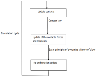
During each calculation cycle, which corresponds to a time increment where the speed and acceleration are considered constant, two operations are carried out (see figure 1): contact updating and particle displacement updating.
Contact updating involves determining contact losses, creating new contacts, and locating them. This enables the contact forces to be updated for each contact by applying the force/displacement contact law.
Knowing the contact forces, the fundamental principle of dynamics is applied to update the particle displacements.
This procedure is repeated for each calculation cycle.
Figure 1. Shows the PFC2D calculation cycle diagram
[6]
O. C. Zienkiewicz, C. Humpheson & R. W. Lewis, Associated and non-associated visco-plasticity and plasticity in soil mechanics, Géotechnique 25, No 4, 1975, pp. 671-689.
[6]
.
2.3. Contact Laws
The calculation code includes several types of predefined contact laws.
These include two elastic contact laws: linear elastic contact and a non-linear elastic contact of the Hertz-Mindlin type.
Additionally, there is a Coulomb-type sliding model and two bonding (cohesive) contact models that create a glue-like contact between particles in contact. These contacts are destroyed if the forces involved exceed the set resistances. It is important to note that bond contacts can only be defined for contacts between particles and not with walls.
Bond contacts introduce cohesion, causing the contact to develop tensile and shear strength. This type of contact only transmits a force, such as compression, deduced from the contact stiffnesses based on the defined elastic contact or traction.
The parallel contact introduces the presence of a material between two particles in contact. This type of contact transmits force and moment in parallel with classic elastic or bond contact. Unlike bond contact, sliding is possible.
3. Study of the Model and Analysis Using PFC2D Software
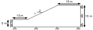
An embankment formed by a homogeneous soil mass with a slope of 2h:1v (approximately 26.57°) is considered. Figure 2 illustrates the geometry of this problem, and Table 1 provides the mechanical properties.
R. Hamza-Cherif, Étude des mouvements de pentes par le code de calcul PFC2D [Study of slope movements by the calculation code PFC2D], 2009, mémoire de Magister, Tlemcen, Algérie.
[7]
MATALLAH M., LABORDERIE C., Inelasticity–damage-based model for numerical modeling of concrete cracking, Engineering Fracture Mechanics, Vol. 76, 2009, p. 1087-1108.
[8]
RAGUENEAU F., Comportements endommageants des matériaux et des structures en béton armé. Mémoire d’habilitation à diriger des recherches [Damaging behaviour of reinforced concrete materials and structures. Habilitation thesis to lead research], Université Pierre et Marie Curie, Paris 6, 2006.
[3, 7, 8]
.
Table 1. Mechanical properties of the soil
[4]
Itasca Consulting Group, Manuel d’utilisation de PFC2D version 3.0 [PFC2D User Manual version 3.0], 2002, Minneapolis, Minnesota (USA).
[12]
Lysmer, J., Ostadan, F., Tabatabaie, M., Vahdani, S. & Tajirian, F. (1988) «SASSI - A System for Analysis of Soil-Structure Interaction» User’s Manual. Berkeley: University of California, Berkeley 1988.
[4, 12]
.
Parameters
values
Mass density,
2000
Cohesion, c (Pa)
3000
Friction angle,
20
Young's modulus, E(Pa)
2,0
Fish factor,
0,25
The safety coefficient (Fs) and fracture surface were determined using FLAC software (Fast Lagrangian Analysis of Continua)
[4]
Itasca Consulting Group, Manuel d’utilisation de PFC2D version 3.0 [PFC2D User Manual version 3.0], 2002, Minneapolis, Minnesota (USA).
[5]
Itasca Consulting Group, Manuel d’utilisation de FLAC version 4.0 [FLAC version 4.0 User Manual], 2002, Minneapolis, Minnesota (USA).
[4, 5]
, a two-dimensional calculation code based on the explicit finite difference method. FLAC is commonly used to solve geotechnical problems, such as landslides.
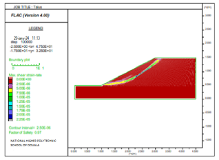
Figure 3. Shows the coefficient of safety and tangential stress.
Figure 3 displays the tangential stress rate and safety coefficient. The safety coefficient is calculated as Fs = 0.97, indicating that the slope is unstable (Fs < 1.50) and there is a risk of slope movement in the form of a circular failure surface. The shape of this surface is due to the presence of a continuous, homogeneous medium.
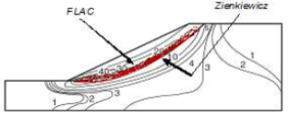
Figure 4 shows the superposition of the results found. It indicates that the two fracture surfaces have similar geometric shapes.
3.1. Analysis Was Conducted Using PFC2D Software
This section models the problem as a discontinuous medium, specifically a granular medium, in contrast to conventional modelling which is based on continuous media. The use of circular elements to model a granular medium is well-suited for this type of problem and is accurately calculated by the PFC2D code.
Table 2. Displays the mechanical properties (micro-parameters).
Parameter
values
Grain density,
2381
Normal stiffness,(N/m)
4,0
Tangential stiffness,(N/m)
1,6
Friction coefficient,
0,1317
Max. radius, (m)
0,10
Maximum radius, (m)
0,08
Porosity, n(-)
0,16
Table 2 presents the mechanical characteristics of the linear elastic contact model in the PFC2D calculation code. These parameters were determined by Preh
[9]
KOTRONIS P., Cisaillement dynamique de murs en béton armé. Modèles simplifies 2D et 3D [Dynamic shearing of reinforced concrete walls. Simplified 2D and 3D models]. Thèse de Doctorat, Ecole normale supérieure de Cachan, Cachan, 2000.
[10]
KOTRONIS P., RAGUENEAU F., MAZARS J., A simplified modelling strategy for R/C walls satisfying PS92 and EC8design, Engineering Structures, 27, 2005, p. 1197-1208.
[9, 10]
through a calibration study (macro-micro transition).
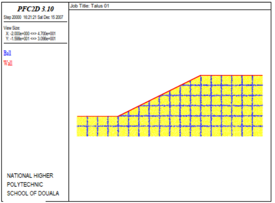
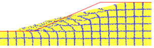
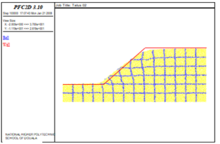
Figure 5 displays the geometry of the slope in its initial state, prior to the application of the gravity field, with 15133 particles. The red line represents the initial surface of the embankment. The particles are coloured in a grid format with a square size of 2.5m to provide a clear view of the deformations.
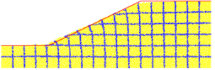
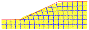
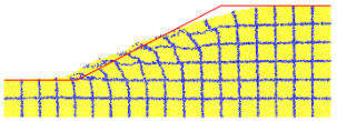
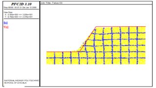
Figures 6, 7, 8 and 9 displays the stages of embankment deformation during various calculation cycles. Deformations become visible after the gravity field is applied
[11]
G. RASTIELLO, «Influence de la fissuration sur le transfert de fluide dans les structures en béton. Stratégie de modélisation probabiliste et étude expérimentale.» [Influence of cracking on fluid transfer in concrete structures. Probabilistic Modeling Strategy and Experimental Study], Thèse de Doctorat, université de Paris-Est, (2013) 192 p.
[13]
Bathurst R. J., Viachopoulos N., Welters D. L., Burgess P. G., Allen T. M., 2006. The influence of facing of stiffness on the performance of two geosynthetic reinforced soil retaining walls. Doc Can. Geotech. J. Vol. 43, p1-13.
[11, 13]
, as evidenced by the coloured grid of particles and the inclination of the vertical and horizontal lines towards the foot of the slope. These deformations are caused by a creep of the granular material.
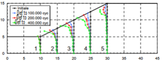
Figure 10. Shows the profiles of the moving sections.
Figure 10 displays the deformations of each section profile generated by PFC2D.
1) The graph shows that Profile 1 underwent deformations of approximately 1m due to a vertex translation in the first 100,000 cycles, which remained constant throughout the simulation.
2) Profile no. 2 experienced horizontal translations of the last three summit points (2.5m) while maintaining a consistent height. This indicates that the slope has formed a bead of displaced material.
3) Profiles 3 and 4: the displacements of the summit points followed the initial slope of the embankment; this region of the embankment underwent a creep of the material following the angle of the slope.
4) Profile 5: the deformation is concentrated at the top (3 m); this represents the head of the slope. This deformation is due to material creep in the lower part.
3.2. Comparison of Results
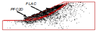
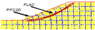
Figure 11 displays the superposition of the velocity vector field generated by PFC2D at 200,000 cycles, with the tangential stress contour generated by FLAC. The concentration of velocity vectors is evident above the fracture surface. Figure 12 superimposes the deformation of the particle grid with the tangential stress contour. It can be observed that the parts susceptible to sliding are approximately the same.
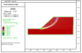
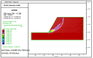
In this section, we will compare the results of FLAC and PFC2D using different examples. Two examples were proposed at different slopes: 1h:1v (45°) and 1h:2v (approximately 63.43°). The mechanical properties are the same as in the previous model (refer to Table 1).
Figures 15 and 16 show the results obtained by the FLAC code for the two examples. Both slopes have circular failure surfaces (foot circle) with safety coefficients of (Fs = 0.54) and (Fs = 0.35) respectively. The deformations of the slope (1h:1v) at 100,000 calculation cycles and the slope (1h:2v) at 60,000 calculation cycles are shown in Figures 15 and 16 respectively. The vertical lines under the slope have tilted towards the foot of the slope. The deformations of the two slopes are of the same shape and type.
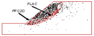
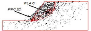
4. Superimposed Results
Figures 17 and 18 shows a comparison after using the two codes. The field of velocity vectors generated by PFC2D is superimposed with the contour of tangential stress rates generated by FLAC. It is observed that the distribution of velocity vectors is concentrated at the level of the fracture area mentioned by FLAC. This indicates that the two calculation codes have resulted in the same fracture surface.
Figure 18. Shows the overlay of the results (Embankment 1h:2v).
5. Conclusions
The use of the PFC2D calculation code for landslide analysis allowed us to determine that the distinct element method is advantageous as it produces rupture shapes that closely resemble reality. The comparison of deformation results between the FLAC and PFC2D codes is almost identical, except that PFC2D does not produce a scarp at the head of the slope. The use of FLAC for slope stability analysis offers several advantages. It allows for easy determination of the safety coefficient and failure surface, and rapid input of geometric and mechanical data. Additionally, simulation time in FLAC is faster compared to PFC2D, taking only a few minutes to a few hours. In contrast, PFC2D does not allow for determination of a safety coefficient for a given slope.
Abbreviations
PFC2D
Particle Flow Code in 2 Dimensions
UDEC
Universal Distinct Element Code
FLAC
Fast Lagrangian Analysis of Continua
Author Contributions
Andre Abanda: Conceptualization, Data curation, Formal Analysis, Methodology, Resources, Software, Supervision, Validation
P. A. Cundall, O. D. L. Strack, A discrete numerical model for granular assemblies, Géotechnique 29, No 1, 1979, pp. 47-65.
[2]
J. L. Durville, G. Sève, Stabilité des pentes. Glissements en terrain meuble [Slope Stability. Soft Landslides], 2002, Techniques de l’ingénieur, traité construction, article C254.
[3]
R. Hamza-Cherif, Étude des mouvements de pentes par le code de calcul PFC2D [Study of slope movements by the calculation code PFC2D], 2009, mémoire de Magister, Tlemcen, Algérie.
[4]
Itasca Consulting Group, Manuel d’utilisation de PFC2D version 3.0 [PFC2D User Manual version 3.0], 2002, Minneapolis, Minnesota (USA).
[5]
Itasca Consulting Group, Manuel d’utilisation de FLAC version 4.0 [FLAC version 4.0 User Manual], 2002, Minneapolis, Minnesota (USA).
[6]
O. C. Zienkiewicz, C. Humpheson & R. W. Lewis, Associated and non-associated visco-plasticity and plasticity in soil mechanics, Géotechnique 25, No 4, 1975, pp. 671-689.
[7]
MATALLAH M., LABORDERIE C., Inelasticity–damage-based model for numerical modeling of concrete cracking, Engineering Fracture Mechanics, Vol. 76, 2009, p. 1087-1108.
[8]
RAGUENEAU F., Comportements endommageants des matériaux et des structures en béton armé. Mémoire d’habilitation à diriger des recherches [Damaging behaviour of reinforced concrete materials and structures. Habilitation thesis to lead research], Université Pierre et Marie Curie, Paris 6, 2006.
[9]
KOTRONIS P., Cisaillement dynamique de murs en béton armé. Modèles simplifies 2D et 3D [Dynamic shearing of reinforced concrete walls. Simplified 2D and 3D models]. Thèse de Doctorat, Ecole normale supérieure de Cachan, Cachan, 2000.
[10]
KOTRONIS P., RAGUENEAU F., MAZARS J., A simplified modelling strategy for R/C walls satisfying PS92 and EC8design, Engineering Structures, 27, 2005, p. 1197-1208.
[11]
G. RASTIELLO, «Influence de la fissuration sur le transfert de fluide dans les structures en béton. Stratégie de modélisation probabiliste et étude expérimentale.» [Influence of cracking on fluid transfer in concrete structures. Probabilistic Modeling Strategy and Experimental Study], Thèse de Doctorat, université de Paris-Est, (2013) 192 p.
[12]
Lysmer, J., Ostadan, F., Tabatabaie, M., Vahdani, S. & Tajirian, F. (1988) «SASSI - A System for Analysis of Soil-Structure Interaction» User’s Manual. Berkeley: University of California, Berkeley 1988.
[13]
Bathurst R. J., Viachopoulos N., Welters D. L., Burgess P. G., Allen T. M., 2006. The influence of facing of stiffness on the performance of two geosynthetic reinforced soil retaining walls. Doc Can. Geotech. J. Vol. 43, p1-13.
Abanda, A., Olivier, L., Joseph, B., Fokwa, D., Christophe, K. W. (2024). Application of the Discrete Element Method to Landslides. Journal of Civil, Construction and Environmental Engineering, 9(4), 98-104. https://doi.org/10.11648/j.jccee.20240904.11
Abanda, A.; Olivier, L.; Joseph, B.; Fokwa, D.; Christophe, K. W. Application of the Discrete Element Method to Landslides. J. Civ. Constr. Environ. Eng.2024, 9(4), 98-104. doi: 10.11648/j.jccee.20240904.11
Abanda A, Olivier L, Joseph B, Fokwa D, Christophe KW. Application of the Discrete Element Method to Landslides. J Civ Constr Environ Eng. 2024;9(4):98-104. doi: 10.11648/j.jccee.20240904.11
@article{10.11648/j.jccee.20240904.11,
  author = {Andre Abanda and Langola Olivier and Bikoun Joseph and Didier Fokwa and Kikmo Wilba Christophe},
  title = {Application of the Discrete Element Method to Landslides
},
  journal = {Journal of Civil, Construction and Environmental Engineering},
  volume = {9},
  number = {4},
  pages = {98-104},
  doi = {10.11648/j.jccee.20240904.11},
  url = {https://doi.org/10.11648/j.jccee.20240904.11},
  eprint = {https://article.sciencepublishinggroup.com/pdf/10.11648.j.jccee.20240904.11},
  abstract = {Civil engineering is defined as all construction related to the ground. In other words, civil engineering is only possible where there is soil. Construction professionals should not face any obstacles when building sustainably in any soil context. Knowledge of the altimetric state, including hills, mountains, valleys, etc., and the subterranean state, including obstacles such as compressible soil, holes, water tables, and rock masses, is crucial to consider before designing infrastructure. This includes the buried part of a structure and the angle of the natural slope in the superstructure to avoid landslides in the infrastructure. Landslides are natural disasters that have had a devastating impact on several populated areas in Cameroon, resulting in numerous fatalities. The most recent landslides recorded in our country occurred in NGOUACHE, MBANKOLO, MOBIL GUINNESS, among others. Preventing disasters requires an understanding of the relationship between construction and landslides to minimize their occurrence and impact. It is important to campaign for sustainable construction that respects the environment. Understanding landslides involves both destructive and non-destructive approaches. This article presents numerical methods for analysing and predicting phenomena. Among these methods, we focus on the discrete element method, which represents the medium as an assembly of circular, rigid particles. We examine three cases to observe the behaviour of the supporting soils and determine the fracture surface. Additionally, we compare our results with those found in the literature.
},
 year = {2024}
}
TY  - JOUR
T1  - Application of the Discrete Element Method to Landslides

AU  - Andre Abanda
AU  - Langola Olivier
AU  - Bikoun Joseph
AU  - Didier Fokwa
AU  - Kikmo Wilba Christophe
Y1  - 2024/07/23
PY  - 2024
N1  - https://doi.org/10.11648/j.jccee.20240904.11
DO  - 10.11648/j.jccee.20240904.11
T2  - Journal of Civil, Construction and Environmental Engineering
JF  - Journal of Civil, Construction and Environmental Engineering
JO  - Journal of Civil, Construction and Environmental Engineering
SP  - 98
EP  - 104
PB  - Science Publishing Group
SN  - 2637-3890
UR  - https://doi.org/10.11648/j.jccee.20240904.11
AB  - Civil engineering is defined as all construction related to the ground. In other words, civil engineering is only possible where there is soil. Construction professionals should not face any obstacles when building sustainably in any soil context. Knowledge of the altimetric state, including hills, mountains, valleys, etc., and the subterranean state, including obstacles such as compressible soil, holes, water tables, and rock masses, is crucial to consider before designing infrastructure. This includes the buried part of a structure and the angle of the natural slope in the superstructure to avoid landslides in the infrastructure. Landslides are natural disasters that have had a devastating impact on several populated areas in Cameroon, resulting in numerous fatalities. The most recent landslides recorded in our country occurred in NGOUACHE, MBANKOLO, MOBIL GUINNESS, among others. Preventing disasters requires an understanding of the relationship between construction and landslides to minimize their occurrence and impact. It is important to campaign for sustainable construction that respects the environment. Understanding landslides involves both destructive and non-destructive approaches. This article presents numerical methods for analysing and predicting phenomena. Among these methods, we focus on the discrete element method, which represents the medium as an assembly of circular, rigid particles. We examine three cases to observe the behaviour of the supporting soils and determine the fracture surface. Additionally, we compare our results with those found in the literature.

VL  - 9
IS  - 4
ER  -